


ADAT-LX20

ALESIS
ADAT LX20
Reference Manual

Contents
CONTENTS
Introduction 5
How To Use This Manual 6
Conventions 6
1 SETTING UP AND MAKING CONNECTIONS 7
Unpacking and Inspection 7
Operating Environment 7
Thermal Considerations in Rack Mounting 7
Mounting on a Shelf or Non-Rack Enclosure 8
Avoiding Electromagnetic Interference 8
AC Power Hookup 8
Avoiding Ground Loops 9
Line Conditioners and Protectors 10
Analog Audio Connections 11
About Audio Cables 11
Rear Panel Input and Output Layout 11
Inputs 11
Typical input jack hookups 12
Outputs 13
Sync In/Out 14
Digital Audio Connections 15
About Digital Audio In/Out 15
Footswitches 16
2 LX20 ESSENTIALS 20
About The Display 20
Time Counter 20
Meters 20
Record/Input Lights 20
Blocks 21
Status Indicators 21
Interpolation In dicator 21
Buttons and Controls 21
Power Switch 21
Record Enable Buttons 21
Transport Controls 21
Eject Button 21
Input Select Buttons 22
Pitch Control Buttons 22
Location Buttons 22
Edit, Format, and Select Buttons 22
Auto Motion Buttons 22
Differences Compared to Analog Recording 23
“Threaded” vs. “Unthreaded” Tape 23
Digital Distortion and Headroom 23
Choosing the Right S-VHS Cassette Tape 24
ADAT LX20 Reference Manual 1

Contents
What is Tape Formatting? 24
3 POWER-UP AND TAPE FORMATTING 26
Power-up and Tape Insertion 26
Setting Tape Length 27
How to Format Tapes 28
About Type I and Type II Formats 28
Defeating The Write Protect Tab 28
General Formatting Procedure 29
Recording While Formatting 31
Re-Formatting a Previously Formatted Tape 31
Notes About Formatting 31
Recording a “Benchmark” Tape 31
4 RECORD AND PLAYBACK BASICS 33
Understanding the Time Counter 33
Change Display Format 33
Set the Input Mode for Analog Audio 33
Choose Analog Or Digital Input 34
Digital Input Re-Routing 34
Select Track(s) for Recording 35
Tape Motion Control: The Transport 35
Stop 35
P l ay 36
Record 36
Other Transport Buttons 36
Step-By-Step Procedures 37
Recording 37
Playback 37
Reviewing and Cueing 38
Monitoring 38
Default Mode 38
Auto Input 38
All Input 39
5 AUTOLOCATION AND LOOP FUNCTIONS 41
Autolocation 41
Return to Zero 41
Locate Points 41
Auto Play 42
Auto Return 42
Looped Playback 43
Loop Limit 44
Deferred Play and Record 44
6 PUNCHING AND AUTOMATED R ECORDING 45
2 ADAT LX20 Reference Manual

Contents
Manual Punching Options 45
Transport Controls 45
Record Enable Buttons 45
Footswitch 46
Automated Recording 46
Looped Recording 47
Rehearsing 47
Adjusting Punch Crossfade Time 48
7 PITCH CONTROL 49
8 ABOUT DIGITAL AUDIO IN/OUT 51
ADAT Optical Interface Basics 51
About 16-bit and 20-bit signal transfers 51
Selecting The Digital Output Mode 52
Type II (20-bit) to Type II (20-bit) 52
Type II (20-bit) to Type I (16-bit) 52
9 USING THE LX20 LRC REMOTE 53
10 MULTIPLE LX20/ADAT OPERATION 55
Overview 55
Synchronizing Machines 55
Automatic Renumbering 56
Master/Slave Interaction 57
Achieving Lock 57
Independent Slave Mode 57
Formatting Multiple Tapes 57
Recording Digital Audio 58
Bouncing Tracks Between ADATs 58
Reassigning Channels to Different Tracks 59
Making Digital Backups 60
Making a 16-bit copy from a 20-bit master 61
Recording Digital Audio from Other Sources 61
Digital Clock Considerations 62
Combining LX20s and ADATs 62
LX20 Transport Speed 62
Sample Rate vs. Pitch Control 62
Input Monitoring 63
Polarity Differences 63
Connections 64
11 APPLICATIONS 65
Overview 65
Combined Multitrack/Mixdown Deck 65
ADAT LX20 Reference Manual 3

Contents
Live/Long-Term Recording 66
Locking to Video: Code-Only Master 66
Libraries and Archives 67
Modular Recording 67
Computer Control and MIDI 67
MIDI Systems: Virtual Tracking 67
MIDI Systems: Automated Mixdown 68
MIDI Systems: Virtual Tracks and Automated Mixdown 68
MIDI Machine Control: Virtual Remote Control 68
The ADAT Optical Interface and Hard Disk Recording 69
Digital Audio Transfer Options 69
Typical applications 70
The ADAT-PCR Computer Interface 70
A Real-World Example 71
Sync Issues 71
Hard Disk Backup 71
Pre-Mastering with the LX20 72
APPENDIX A DIGITAL RECORDING CONCEPTS 73
Analog Recording Basics 73
Digital Recording Basics 73
The Advantages of 20-Bit Recording 74
Why S-VHS? 75
APPENDIX B TROUBLESHOOTING 76
Re-Initializing: Try This First 76
Troubleshooting Index 76
Checking Software Version 77
Error Rate Displ ay 78
About Error Rate Readings 78
ADAT Head Life 79
ADAT Head Maintenance 79
Drum Time Display 79
Tape Care and Maintenance 81
Maintenance/Service 82
Cleaning 82
Maintenance 82
Obtaining Repair Service 83
APPENDIX C ERROR CODES 84
Automatic Brake Calibration Procedure 86
Steps To Take Before Calling For Help 87
APPENDIX D SPECIFICATIONS 88
GLOSSARY 90
4 ADAT LX20 Reference Manual

INTRODUCTION
Thank you for purchasing the Alesis ADAT-LX20 20-Bit Digital Audio Recorder.
To take full advantage of the LX20’s functions, and to enjoy long and trouble-free
use, please read this manual carefully.
Here are some of the LX20’s most significant features:
• Low tape cost. The LX20 can record over an hour of audio on a standard S-VHS
tape cassette.
• Superb fidelity. The LX20 offers 20-bit recording to tape using the ADAT Type
II format, along with a choice of a 44.1 or 48 kHz sampling rate (with 64 times
oversampling), for better-than-CD quality sound.
• Digital and analog inputs/outputs. In addition to conventional analog inputs
and outputs, a “master” digital I/O carries all eight tracks simultaneously via
optical cable, allowing for lossless signal transfers between ADAT interfacecompatible devices (tape recorders, hard disk recorders, synthesizers, signal
processors, etc.).
• Easy expandability for more tracks. Multiple LX20s can be synchronized
without any external hardware, and without giving up any tracks, to expand
your digital recording system. Two LX20s give 16 tracks, three LX20s 24 tracks,
and so on. Up to 16 LX20s or other ADAT-family digital recorders can work
together, and all are locked within 20 microseconds (1 sample) accuracy.
Introduction
• Included remote control. Each LX20 comes with the LRC (Little Remote Control)
for remote control of transport, autolocation, and input select functions.
• Optional remote control. The BRC (Big Remote Control) allows for
sophisticated synchronization and overdubbing functions for multiple ADATcompatible machines, remote control of virtually all recorder functions, and
SMPTE read/generate.
• International no-hassles power compatibility. The LX20 accepts any AC
voltage between 90 and 250 volts, so you can use it whether you’re laying down
tracks in L.A, mixing in Munich, or synching in Seoul. (Or dealing with a
brownout in New York City, for that matter.)
• Built-in time code. Each LX20 tape is formatted with a proprietary time code
that is much more accurate than SMPTE, and time-stamps the tape with singlesample accuracy. This allows for machine synchronization without giving up an
audio track, accurate tape counter readings without “slippage,” and intelligent
autolocation functions.
• Compatibility with multi-channel mixdown formats. The LX20 is ideal for
quadraphonic, surround, and theatrical sound applications that require more
than two channels for the final master.
ADAT LX20 Reference Manual 5

Introduction
HOW TO USE THIS MANUAL
Though we recommend you read through the entire manual once, those having
general knowledge about multitrack recorders should use the table of contents and
index to reference specific functions while using the LX20. Here’s how the manual is
organized:
Chapter 1: Setting Up and Making Connections. This covers installation issues as
well as how to connect up the LX20 to other gear in a system.
Chapter 2: LX20 Essentials. This section provides a brief tour of LX20 highlights,
dsecribes some of the buttons and controls, and discusses how to choose the right
tape.
Chapter 3: Power-Up and Tape Formatting. Time to turn on the power and format a
tape before recording.
Chapter 4: Recording and Playback Basics. Here’s the lowdown on shuttling tape,
recording, and playing back.
Chapter 5: Autolocation and Loop Functions. The LX20 can find specific points on
tape, as well as loop continuously between two points.
Chapter 6: Punching and Automated Recording. This chapter describes how to
replace sections of previously-recorded tracks.
Chapter 7: Pitch Control. If you’re ever had to retune a piano to a track, you’ll
appreciate the LX20’s ability to tune a track to piano instead.
Chapter 8: About Digital Audio In/Out. All ADAT-compatible devices include a
fiber optic interface that can carry 8 channels of audio simultaneously. This
chapter tells how to get the most out of this advanced interface.
Chapter 9: Using the LRC Remote. The LX20 comes with a remote control unit that
duplicates many front panel functions.
Chapter 10: Multiple LX20/ADAT Operation. ADAT-compatible devices can work
together synergistically to create a sophisticated recording system, as detailed in
this chapter.
Chapter 11: Applications. There’s a lot more to the LX20 than meets the eye, such
as “snapshot” automation, combined master/mixdown deck, virtual MIDI tracks for
instrument parts and signal processor control, and more.
Appendices. Features an explanation of digital audio recording concepts, troubleshooting, maintenance and service information, specifications, a Glossary and an
Index.
Conventions
All front panel buttons and rear panel connectors are referred to in this manual just
as their names appear on the LX20, using all capital letters (Examples: PLAY
button, AUTO INPUT button, etc.).
When something important appears in the manual, an icon (like the one on the left)
✪
6 ADAT LX20 Reference Manual
appears in the left margin. This symbol indicates that this information is vital
when operating the LX20.

Chapter 1 - Setting Up and Making Connections
CHAPTER 1
SETTING UP AND
MAKING CONNECTIONS
UNPACKING AND INSPECTION
Your ADAT-LX20 was packed carefully at the factory. The shipping carton was
designed to protect the unit during shipping. Please retain this container in the
highly unlikely event that you need to return the LX20 for servicing.
The shipping carton should contain the following:
• ADAT-LX20 with the same serial number as shown on shipping carton
• Power Cable
• Optical Cable
• LRC remote control unit
• This instruction manual
• Blank S-VHS ST-120 cassette
• Alesis warranty card
Register your purchase so that you may be informed of upgrades. If you have not
✪
already filled out your warranty card and mailed it back to Alesis, please do so
now.
OPERATING ENVIRONMENT
HERMAL CONSIDERATIONS IN RACK MOUNTING
T
You can mount the LX20 in an equipment rack (taking up 3 rack spaces) or place it on
a table or shelf. When you install it, note that heat is the major enemy of electronic
equipment. Please observe the following:
• The LX20 is designed to perform properly over a range of ambient temperatures
from 10° C to +40° C (50° F to 104° F), in up to 80% non-condensing humidity.
These are not absolute limits, but Alesis cannot guarantee that the LX20 will
meet its published specs or remain reliable if operated outside of these ranges.
• Always allow adequate ventilation behind the LX20. Do not seal any enclosure
that holds the LX20. It is not necessary to leave an empty rack space above or
below the LX20 unless it runs hot enough to affect equipment above or below it.
If your environment is unusually warm and not air conditioned, space between
units will help the units run cooler and may lessen tape oxide shedding.
• Do not mount the LX20’s rack at a an angle. The LX20 should not be angled back
or mounted vertically.
ADAT LX20 Reference Manual 7

Setting Up and Making Connections - Chapter 1
MOUNTING ON A SHELF OR NON-RACK ENCLOSURE
To mount the LX20 on a shelf or other flat surface, Alesis recommends attaching
stick-on rubber feet to avoid scratching the shelf’s surface with the deck’s bottom.
Please observe the general comments on thermal considerations given under
“Thermal Considerations in Rack Mounting” no matter where or how the deck is
mounted.
AVOIDING ELECTROMAGNETIC INTERFERENCE
Like all tape machines, the LX20 uses magnetic tape that can be sensitive to
electromagnetic interference. Generally this is not a problem, but avoid mounting
the LX20 next to devices that generate strong magnetic fields such as power
amplifiers, monitors and video display devices, speakers, etc.
AC POWER HOOKUP
With the LX20 off, plug the power cord’s female end into the LX20’s POWER
INPUT socket, and the male (plug) end into a source of AC power. It’s good practice
not to turn on the LX20 until all other cables are hooked up.
The LX20 works with any AC voltage from 90 to 250 volts, 50 to 60 Hz. This
eliminates the need for transformers or voltage switches. Your LX20 was supplied
with the correct power cord for your country or local area, however only the
following alternative power cords are approved for use with ADAT:
• For 90-120 VAC 50/60 Hz operation in the US, Canada and/or Japan, use Alesis
UL/CSA power cord #7-41-0001.
• For 240 VAC 50 Hz operation in England, use Alesis Power cord #7-41-0004.
• For 220 VAC 50 Hz operation in Europe and Scandinavia, use Alesis EU power
cord #7-41-0002.
• For 240 VAC 50 Hz operation in Australia, use Alesis AS power cord #7-41-0003.
The LX20’s IEC-spec AC cord (do not substitute any other AC cord) is designed to feed
an outlet that includes three pins, with the third, round pin connected to ground. The
ground connection is an important safety feature and should never be “lifted.”
Unfortunately, the presence of a third ground pin does not always indicate that an
outlet is properly grounded. Use an AC line tester to determine this. If the outlet is
not grounded, consult with a licensed electrician.
Alesis cannot be responsible for problems caused by using the LX20 or any associated
equipment with improper AC wiring.✪
8 ADAT LX20 Reference Manual
Chapter 1 - Setting Up and Making Connections
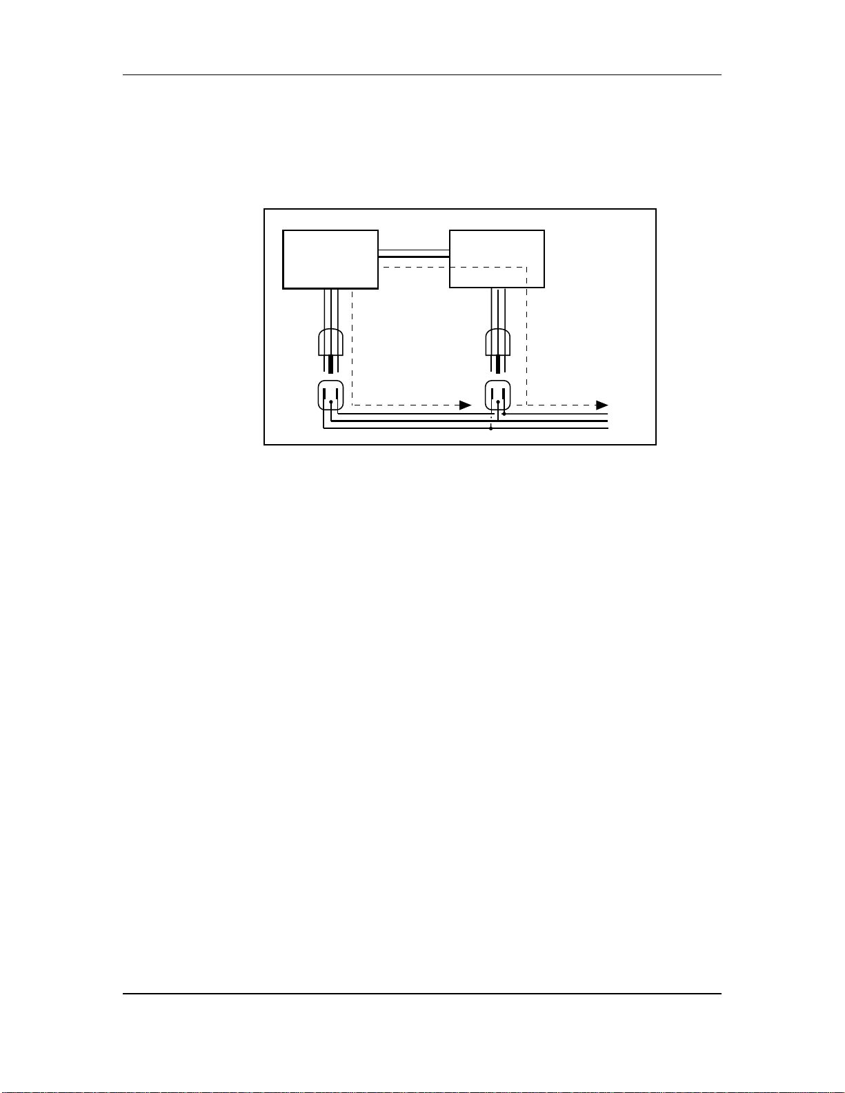
AVOIDING GROUND LOOPS
In today’s studio, there are many opportunities for ground loop problems to occur.
These show up as hums, buzzes, or sometimes radio reception, and can occur if a
piece of equipment “sees” two or more different paths to ground, as shown below.
shielded
cable
Device A
path 1
path 2
Device B
To AC power service
One path goes from device A to ground via the ground terminal of the threeconductor AC power cord, but A also sees a path to ground through the shielded
cable and AC ground of device B. Because ground wires have a small amount of
resistance, small amounts of current can flow through ground and generate a voltage
along the cable shield. This signal may end up getting induced into the hot
conductor.
The loop can also act like an antenna into which hum is induced, or can even pick up
radio frequencies. Furthermore, many components in a circuit connect to ground. If
that ground is “dirty” and contains noise, it might get picked up by the circuit.
Ground loops cause the most problems with high-gain circuits, since massive
amplification of even a tiny bit of noise can give an audible signal.
Most ground loop problems can be solved by plugging all equipment into the same
grounded AC source. However, it is important to make sure that the AC source is not
overloaded and is properly rated to handle the gear plugged into it.
For really tough cases, you may need to break the connection that causes the loop
condition. If your circuits are balanced, one way to do this is to simply break the
shield of the shielded audio cable at some point, usually by disconnecting it from
ground at one jack. (The other end should remain connected so that the shielding
properties are retained, even if there is no direct path for ground.)
Please note that not all hums and buzzes are caused by ground loops; your cables
must be of high quality, particularly with -10 dBV setups.
ADAT LX20 Reference Manual 9

Setting Up and Making Connections - Chapter 1
LINE CONDITIONERS AND PROTECTORS
Although the LX20 can tolerate typical voltage variations, the AC line voltage
may contain spikes or transients that can possibly stress your gear and, over time,
cause a failure. There are three main ways to protect against this, listed in
ascending order of cost and complexity:
• Line spike/surge protectors. Relatively inexpensive, these are designed to
protect against strong surges and spikes, acting somewhat like fuses in that
they need to be replaced if they’ve been hit by an extremely strong spike.
• Line filters. These generally combine spike/surge protection with filters that
remove some line noise (dimmer hash, transients from other appliances, etc.).
• Uninterruptible power supply (UPS). This is the most sophisticated option. A
UPS provides power even if the AC power line fails completely. Intended for
computer applications, a UPS allows you to complete an orderly shutdown of a
computer system in the event of a power outage, and the isolation it provides
from the power line minimizes all forms of interference — spikes, noise, etc.
If your AC power is unstable or subject to occasional browns-outs or interruptions, use
a professional power conditioner or uninterruptible power supply. Some people who
have experienced problems with ADAT operation have had those problems
disappear completely after installing proper power conditioning.
10 ADAT LX20 Reference Manual

Chapter 1 - Setting Up and Making Connections
ANALOG AUDIO CONNECTIONS
BOUT AUDIO CABLES
A
The connections between the LX20 and your studio are your music’s lifeline, so use
only high quality cables. These should be low-capacitance shielded cables with a
stranded (not solid) internal conductor and a low-resistance shield. Although
quality cables cost more, they do make a difference. Here’s how to route cables to
the LX20:
• Do not bundle audio cables with AC power cords.
• Avoid running audio cables near sources of electromagnetic interference such as
transformers, monitors, computers, etc.
• Do not place cables where they can be stepped on. Stepping on a cable may not
cause immediate damage, but it can compress the insulation between the center
conductor and shield (degrading performance) or reduce the cable’s reliability.
• Avoid twisting the cable or having it make sharp, right angle turns.
• Never unplug a cable by pulling on the wire itself. Always unplug by firmly
grasping the body of the plug and pulling directly outward.
✪
When connecting audio cables and/or turning power on and off, make sure that all
devices in your system are turned off and the volume controls are turned down.
REAR PANEL INPUT AND OUTPUT LAYOUT
The LX20’s rear panel has 8 unbalanced phono jack inputs, and 8 unbalanced phono
jack outputs.
INPUTS
The inputs feed signals into the LX20 for recording. These inputs are compatible
with low-impedance, unbalanced, -10 dBV outputs typical of mixers, synthesizers,
samplers, direct boxes, etc. Guitar and bass require preamplification before feeding
these inputs.
ADAT LX20 Reference Manual 11

Setting Up and Making Connections - Chapter 1
Here’s how the input jacks and plugs are wired:
TipSignal
SleeveGround
Tip
Sleeve
TYPICAL INPUT JACK HOOKUPS
You typically patch the following into the inputs:
• Console direct tape outs. With many mixing consoles, such as the Alesis Studio
24, each mixer channel has a direct output. These can patch a channel directly
to tape, bypassing most mixer circuitry. You would normally patch the direct
out from channel 1 into LX20 input 1, channel 2 into LX20 input 2, etc. This is
preferred when the signals going to tape require none of the mixer’s routing or
processing features.
• Mixer bus outputs. One important mixer characteristic is the number of output
busses. Each output bus represents a mix of input faders, auxiliary sends, etc. Use
bus connections when the mixer performs grouping, premixing, effects, etc. Using
the bus outputs puts more circuitry between the input signals and LX20 compared
to using direct outs, although since most routing can be done at the mixer, you’ll
seldom need to do any repatching.
The LX20 can be optimized to work with 2 bus, 4 bus, or 8 bus mixers, as described
later. You would hook these up as follows.
2 bus mixer: Connect the main bus outs to inputs 1 and 2
4 bus mixer: Connect the main bus outs to inputs 1-4
8 bus mixer: Connect the main bus outs to inputs 1-8
For example, with an 8-bus mixer, you would normally patch output bus 1 to
LX20 input 1, output bus 2 to LX20 input 2, etc. until output bus 8 patches into
LX20 input 8.
• A combination of direct outputs and bus outputs. Some situations require a
combination of the two approaches. Example: Consider a live gig where you
want to record two vocal mics, four mics on drums, two direct feeds from guitar
and bass amps, and one direct feed from keyboards. The vocals, bass, guitar, and
keyboards could be taken direct and go to five LX20 tracks. The four drum mics
can be mixed to stereo within your mixer sent to the submix outs, then go to two
LX20 tracks. The remaining LX20 track could be used to record audience sounds or
capture one of the instruments in stereo, if applicable.
12 ADAT LX20 Reference Manual

Chapter 1 - Setting Up and Making Connections
OUTPUTS
The -10 dBV outputs use phono jacks, and carry signals at a nominal -10 dBV level.
These connect to your mixer’s channel tape returns or line inputs. You would
normally connect output 1 to mixer line input 1 or tape return 1, output 2 to mixer line
input 2 or tape return 2, etc.
ADAT LX20 Reference Manual 13
Setting Up and Making Connections - Chapter 1
SYNC IN/OUT
The two rear panel DB-9 connectors marked SYNC IN and SYNC OUT synchronize
two or more ADAT-family devices, such as the LX20, XT20, M20, original ADAT,
ADAT-XT, and/or a computer hard disk audio recording/editing system using the
ADAT-PCR sound card or similar device.
Synchronization requires a male-to-male, 9-pin D connector cable for each
additional machine in the chain. These cables are available in various lengths
from Alesis or your dealer and should be Alesis-approved; improper cables (such as
those used for computers) may not function correctly.
In such a system, you are basically treating all connected machines as though they
were a large multitrack unit. The first LX20 or ADAT in the chain is the “master,”
and all other connected units are called “slaves.” However, each slave can also be
used independently when the master machine is stopped.
For details about using multiple LX20s and/or ADATs, refer to Chapter 10.
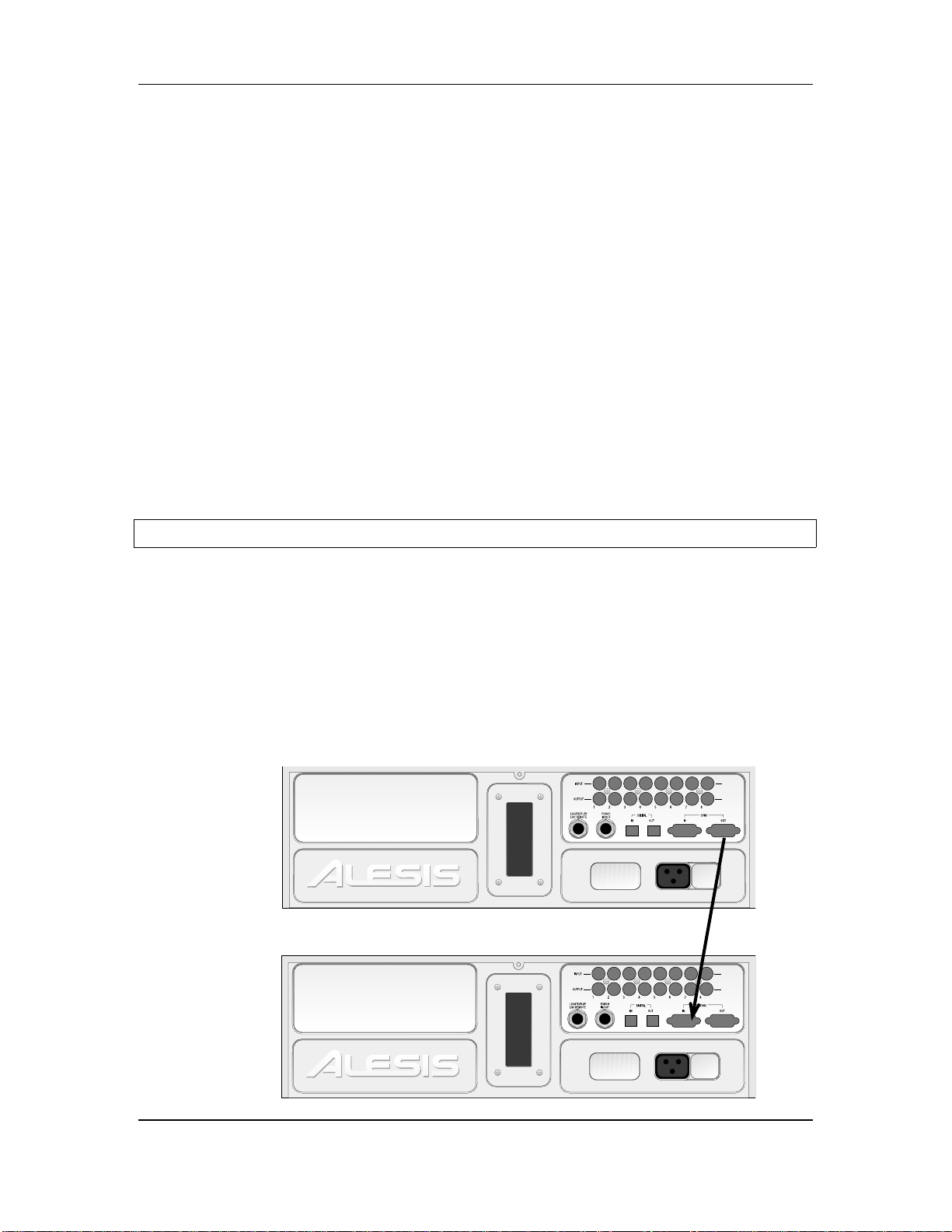
To synchronize multiple LX20s and/or ADATs:
❿ Locate the SYNC IN and SYNC OUT connectors.
❡ Connect one end of a male-to-male, 9-pin connector cable to the master’s SYNC
OUT jack.
① Connect the other end of the cable to the first slave’s SYNC IN jack.
➃ For additional slaves, connect one end of a male-to-male, 9-pin D connector
cable to the first slave’s SYNC OUT jack, and the other end to the second
slave’s SYNC IN jack. Its SYNC OUT jack then connects to the third slave’s
SYNC IN jack, and so on.
The following illustration shows two LX20s synchronized together.
INPUT
OUTPUT
INPUT
OUTPUT
14 ADAT LX20 Reference Manual

Chapter 1 - Setting Up and Making Connections
DIGITAL AUDIO CONNECTIONS
The digital input and output carries all eight tracks on a single fiber optical cable
(called the ADAT Optical Interface, and sometimes nicknamed the ADAT “Light
Pipe”). This powerful feature allows you to transfer digital audio between multiple
ADAT-compatible devices.
ABOUT DIGITAL AUDIO IN/OUT
The ADAT Optical Interface cables carry digital audio between ADAT compatible
products such as multiple LX20s and ADATs, the QuadraVerb 2, Q20, many Alesis
keyboards, the ADAT-PCR computer interface card, and third-party products such
as the Digidesign ADAT Bridge and Yamaha 02R digital mixer. Since the fiber
optic connector carries the digital information for all 8 tracks, it is also useful for
backing up all tracks in one pass.
Digital bussing requires a fiber optical cable (included) for each LX20 in the system
(or any other ADAT-compatible product). Additional cables are available from
Alesis or your dealer in various lengths up to 16 feet. You can make this connection
while power is on or off, and the machines do not need to be turned on in any
particular order.
Examples: Probably the most common application is “cloning” one ADAT tape to a
second machine for backup. Basically, you patch the fiber optic output from the
machine with the tape to be backed up (the master) to the fiber optic input of the
machine doing the backup (the slave). Record-enable the slave tracks and press
play on the master to copy the original tape.
Another application is transferring all 8 tracks from an ADAT to a hard disk
recording system for editing. You would patch the ADAT fiber optic output to an
ADAT-PCR interface card’s fiber optic input, press play on the ADAT, and record on
the hard disk system. To transfer the edited data back to the ADAT for storage
and/or backup, patch the ADAT-PCR interface’s fiber optic out to the ADAT’s fiber
optic in, and play back the hard disk data while the ADAT is recording.
These and other applications are described in more detail in Chapters 10 and 11.
To connect the digital optical network:
❿ Locate the DIGITAL IN and DIGITAL OUT connectors.
Remove the connectors’ plugs (if present) and store for later use.
❡ Connect one end of the fiber optic cable into the DIGITAL OUT jack of the first
machine in the system.
Remove the clear, plastic tube covering each end of the cable (if present). The
cable is non-polarized, so either end can insert into the optical output.
① Connect the other end of the fiber optic cable to the DIGITAL IN of the second
machine in the system.
Tip: if the machines are on, the end of the cable from the source machine will
glow red.
ADAT LX20 Reference Manual 15
Setting Up and Making Connections - Chapter 1
➃ For each additional machine, connect one end of an additional fiber optic cable
to the second machine’s DIGITAL OUT jack, and the other end to the third
machine’s DIGITAL IN jack. Its DIGITAL OUT jack then connects to the fourth
machine’s DIGITAL IN jack, and so on.
➄ Finally, connect one end of a fiber optic cable to the last machine’s DIGITAL
OUT jack, and the other end to the first machine’s DIGITAL IN jack.
This last step creates a loop, making the digital bus accessible to all machines
connected to it.
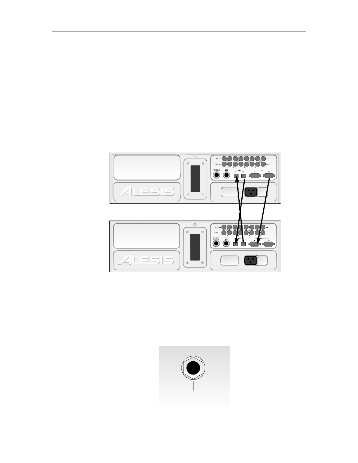
The following diagram shows how to hook up the Sync and Optical Interface
connectors in a setup with two LX20s.
When connecting more than two machines, always connect the optical cables in the
✪
same order as the sync cables (1 to 2, 2 to 3, etc.), so that the digital routing will
work correctly.
INPUT
OUTPUT
FOOTSWITCHES
The LX20 provides one footswitch connector using a 1/4" stereo jack named
LRC/PUNCH.
• LRC allows patching in the LRC Remote control
• PUNCH is for punch in/out control using a footswitch.
LRC/PUNCH
Tip = LRC Remote
Ring = Punch In/Out
Sleeve = Ground
INPUT
OUTPUT
16 ADAT LX20 Reference Manual

Chapter 1 - Setting Up and Making Connections
ADAT LX20 Reference Manual 17
Setting Up and Making Connections - Chapter 1
There are three ways to use this jack.
• Footswitch only. Plug a momentary, single-pole/single-throw footswitch
(either normally open or normally closed) halfway into the jack so that the
footswitch plug tip connects to the jack ring connection. In other word, plug in
only until the tip reaches the first detent. Plug in the footswitch prior to
power-up so that the LX20 can configure itself for the type of footswitch being
used. If you decide to plug in a footswitch after already starting a session, turn
off the LX20, plug in the footswitch, then turn theLX20 back on again.
• LRC only. Plug the LRC plug fully into the jack.
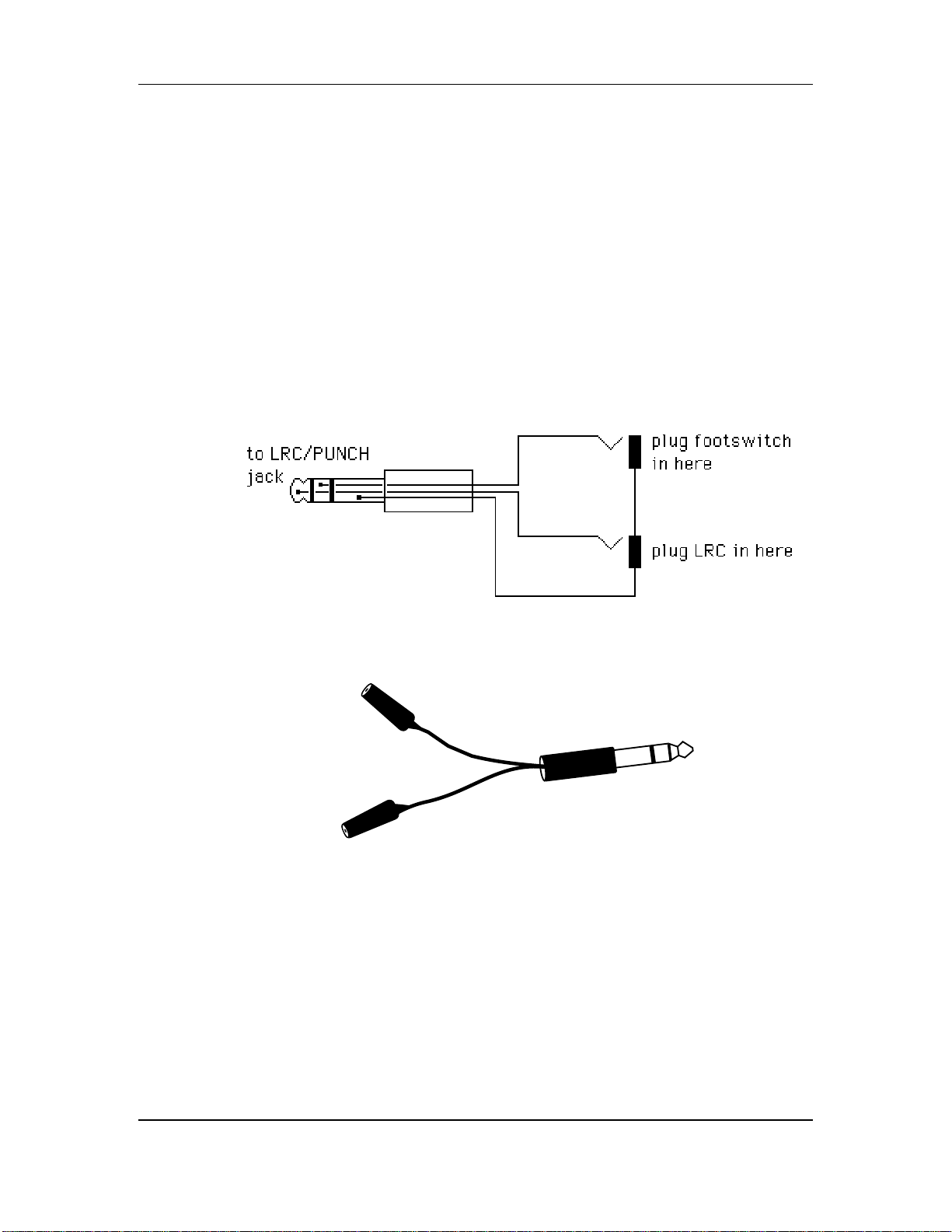
• Footswitch and LRC. Use an adapter that breaks out a stereo plug into two mono
jacks. Plug the footswitch into the mono jack that connects to the stereo jack ring
connection, and the LRC into the mono jack that connects to the stereo jack tip
connection. The following diagram shows the wiring scheme.
This cable is available from several manufacturers, such as Radio Shack (#274-302)
and Hosa (YPP-118).
18 ADAT LX20 Reference Manual

Chapter 1 - Setting Up and Making Connections
ADAT LX20 Reference Manual 19
LX20 Essentials - Chapter 2
LX20 ESSENTIALS
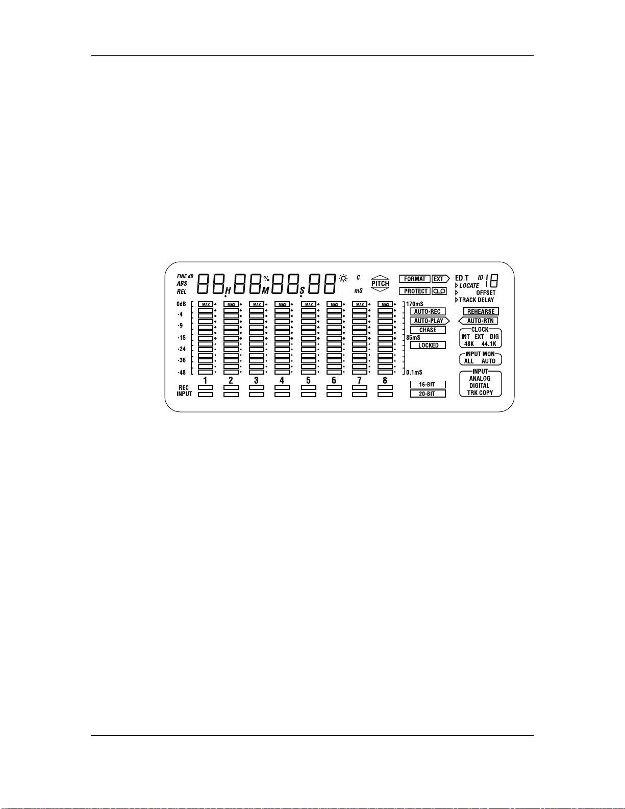
ABOUT THE DISPLAY
The LX20’s display shows the current level of each of the eight audio tracks, the
tape position (in hours, minutes, seconds, and 100ths of seconds or frames), and the
current modes of the many available parameters. It also provides a “window” for
various editable parameters. With all segments lit (which would not happen in
normal operation), the display looks as follows:
CHAPTER 2
MACH
You don’t need to remember the significance of all these indicators right now. But
we do want to call your attention to certain parts of the display that are important
in learning the LX20.
TIME COUNTER
The time display shows the current location of the tape in hours, minutes, seconds,
and optionally, “frames” (1/30th of a second).
METERS
The 8 meters show input signal levels or the levels recorded on tape, depending on
whether you’re monitoring the inputs or tape outputs. The uppermost segment
indicates 0 dB. Keep signals below this point, as lighting the 0 dB segment
indicates distortion.
RECORD/INPUT LIGHTS
Located directly below the meters, the red REC indicators show a track’s record
status. The blue INPUT indicator show the input monitor status.
20 ADAT LX20 Reference Manual

BLOCKS
There are three ”blocks” located in the lower right-hand corner: Clock, Input Mon,
and Input. Each block shows the selected option for the block’s parameter.
STATUS INDICATORS
These are individual status indicators. For example, to the left of the Input Mon
block, there are status indicators that show whether the tape being played is in 16bit or 20-bit format. Other indicators show whether particular locate functions are
enabled, whether a cassette is inserted in the cassette well, and so on.
INTERPOLATION INDICATOR
A small asterisk-like indicator to the upper right of the time counter’s last digit
lights whenever the LX20 detects an error significant enough to require
interpolating data (in others words, the LX20 has to make an educated guess as to
what the audio should be). Should this light flash, it’s a good idea to clean the
tape heads and make a backup copy of your tape. See Chapter 10, section QQ, for
more information.
BUTTONS AND CONTROLS
Chapter 2 - LX20 Essentials
There are several buttons on the front panel that control LX20 functions, as shown
below:
POWER SWITCH
The LX20 power switch is an “intelligent” switch. It operates normally (push once
to turn and once to turn off) but also does two cool tricks:
• If the LX20 is connected to a barrier strip, it will detect when the barrier strip
has been turned on, and automatically power-up.
• If the LX20 is turned off and you insert a cassette into the well, the LX20 will
automatically power-up.
RECORD ENABLE BUTTONS
Each recording enable button corresponds to its like-numbered track, and controls
the track’s record status. They are also sometimes used in combination with other
buttons to select more advanced options.
TRANSPORT CONTROLS
These control tape movement (REWIND, FFWD, STOP, PLAY, and RECORD).
EJECT BUTTON
If you guessed this ejects the cassette, you’re right.
ADAT LX20 Reference Manual 21

LX20 Essentials - Chapter 2
INPUT SELECT BUTTONS
These determine how signals, both analog and digital, are routed to the LX20.
PITCH CONTROL BUTTONS
These increase or slow down the playback and record speeds to change pitch.
LOCATION BUTTONS
The LX20 can find particular places on tape. Example: You might want to shuttle
rapidly between a chorus and verse while overdubbing; by storing these locations,
you can push the corresponding button to tell the tape to “go fetch,” and park the
tape at the desired location.
EDIT, FORMAT, AND SELECT BUTTONS
These are really individual functions grouped in the same general area. They will
be described in detail as needed.
AUTO LOOP/AUTO RECORD BUTTONS
The LX20 can automate certain tape movement procedures, such as automatically
returning to a particular point after overdubbing, playing a section repeatedly,
automated “punching” to record over a specific section of a track (e.g., a bad phrase
in an otherwise perfect vocal), and so on. The Auto Play, Auto Return and Auto
Record buttons, in conjunction with the Location buttons, control the auto functions.
22 ADAT LX20 Reference Manual

Chapter 2 - LX20 Essentials
DIFFERENCES COMPARED TO ANALOG RECORDING
Recording on the LX20 is very similar to most multitrack tape machines. With a
formatted tape loaded, put one or more tracks into record-ready, adjust record levels
on your mixer, set the input monitor mode, locate to where you want to begin
recording, and engage record. However, there are two main differences, described
next.
“THREADED” VS. “UNTHREADED” TAPE
The LX20 uses a rotating head drum which records and plays back digital audio
signals from tape. Even when the tape is stopped, it remains “threaded” or engaged
against the spinning head drum for a period of time. This allows for going into play
or record faster, as well as provides “cue” and “review” functions that let you
monitor the tape audio at faster-than-normal play speeds. When threaded and
stopped, the STOP button LED is lit steadily.
When the tape is unthreaded (the STOP LED flashes), it takes a little bit of time
for the tape to wrap around the head drum before it can go into play or record. Cue
and review functions are not possible while the tape is unthreaded.
When the tape is threaded and stopped, you can manually unthread it by pressing
the STOP button. The STOP LED will flash, indicating the tape is now unthreaded.
Pressing either PLAY or STOP, or PLAY and RECORD to engage recording, rethreads the tape.
If the tape is threaded, and no transport activity (play, record, rewind, etc.) occurs
for 4 minutes, the tape will automatically unthread itself to minimize tape wear.
DIGITAL DISTORTION AND HEADROOM
With analog tape, it is common to record “in the red” as distortion increases slowly
with increasing level. Small amounts of analog distortion may not only be difficult
to hear, but may even be considered desirable. Another reason for recording at
elevated levels is the limited dynamic range of analog tape — hitting it with as
much level as possible minimizes noise.
With digital recording, signals remain undistorted up to the 0 (clipping) point, at
which point distortion increases dramatically. Alesis recommends never exceeding
0, and recording at an average level of around -15 to -10 dB. With the exceptional
dynamic range made possible with 20-bit recording, there is no need to “slam”
levels. Giving your signals a little bit of headroom provides a margin of safety
against distortion.
ADAT LX20 Reference Manual 23

LX20 Essentials - Chapter 2
✪
CHOOSING THE RIGHT S-VHS CASSETTE TAPE
We cannot overemphasize the importance of using only premium quality, name
brand S-VHS cassettes such as Quantegy 489 DM Digital Mastering Audio Tape, or
Alesis ADAT Mastering Audio Cassettes. Other acceptable brands include Maxell
XR-S Black, JVC XZ, Sony DASV, BASF Digital Master 938, Apogee AA-40, HHB
ADAT45, and TDK SP Super Pro. The cassette shell, hubs, rollers and tape guides in
S-VHS cassettes are precision devices that properly handle and protect the tape
within them.
Although VHS cassettes may appear to work at first, their unpredictable quality
and less-than-premium formulation will decrease the reliability of your recording.
Inferior tapes not only jeopardize the recordings made on them, they may shed
oxide and leave behind a coating of dirt that will interfere with future recordings,
even if you switch back to premium quality tape. Defective tape may even clog the
head, requiring service. Don’t trust your work to anything less than premium
quality S-VHS tape.
Rewind and fast forward a new tape several times from end to end before attempting
to record on it. This crucial step “unpacks” the tape properly, and leads to more
reliable long-term operation (this is also recommended practice for DAT tapes).
Treat your tapes as the precision, fragile components that they are. Do not expose
them to extremes of heat, cold, or humidity (in other words, don’t leave them in
your car). Never place tapes near magnetic fields (such as power amps, TVs,
monitors, magnets, etc.) and handle tapes gently.
WHAT IS TAPE FORMATTING?
Standard blank S-VHS tapes must first be formatted in an ADAT-family machine
before they can be used. Formatting prepares the tape for recording and
synchronization, as described later.
24 ADAT LX20 Reference Manual

Chapter 2 - LX20 Essentials
ADAT LX20 Reference Manual 25
Power-Up and Tape Formatting - Chapter 3
CHAPTER 3
POWER-UP AND TAPE
FORMATTING
POWER-UP AND TAPE INSERTION
Patch the LX20’s power cord between the rear panel, three-prong power socket and
a properly-wired AC outlet receptacle. Please take account of the grounding
considerations mentioned in Chapter 1.
The LX20 can produce a transient audio signal during power up and power down.
✪
When turning the LX20 on or off, keep the monitor levels low.
Turn the LX20’s power on by pressing the POWER button. At power-up the display
briefly looks like this:
In a few seconds, the display will change depending on the status of the tape in the
transport.
• If a formatted tape is present, the TIME counter will show the elapsed time
since the beginning of the tape (unless it is somewhere in the first two minutes
of tape, called the “lead” and “data” sections):
ABS
0H 15M 48S 21
• If an unformatted tape is present, the FORMAT indicator will flash and the
TIME counter will read:
ABS
n0 F0
• If there is no tape, the display shows:
ABS
-- -- -- --
Insert the tape with the hinged door end first, label side up, until you encounter a
slight bit of resistance. Push gently on the center of the tape cassette until the LX20
draws the tape inward. Never force the tape into the cassette door.
26 ADAT LX20 Reference Manual

SETTING TAPE LENGTH
The LX20 can use tapes longer than the standard ST-120 length (an ST-180 tape
gives over one hour of recording time, an ST-160 gives 53 minutes). The LX20
automatically recognizes ST-60 tapes and adjusts itself accordingly, but cannot tell
apart ST-120, ST-160 or ST-180 tapes.
The LX20 assumes you are using a ST-120 tape. Therefore, you need to set the tape
length on the LX20 when using either ST-160 or ST-180 tapes. To do this, hold the
SET LOCATE button and press the FORMAT button. Each press of the format button
cycles through the following options: ST-60, ST-160, ST-180, and ST-120. When the
display shows the correct tape length, release both buttons.
• Ejecting a tape does not reset the tape length, but powering down resets to T-120.
• If you insert a tape with Tape Length set to something other than ST-120, the
display will briefly flash the selected length to remind you that you are using
a non-standard setting.
• If using multiple LX20s/ADATs, all connected machines must use tapes of the
same length.
Chapter 3 - Power-Up and Tape Formatting
✪
✪
The Tape Length setting and the actual tape’s length must be the same. Never use a
shorter tape length than what the LX20 thinks you’re using.
Below is a list of the four S-VHS tapes the LX20 accepts, with their European
equivalents and approximate recording times:
Type Euro Rec. Time
ST-60 n/a 22 min.
ST-120 SE-180 40 min.
ST-160 SE-240 54 min.
ST-180 SE-260 62 min.
If using tapes longer than ST-120, locating for the first time past the 39 minute
position temporarily slows down (but does not stop) the transport. Each subsequent
location beyond this point acts normally. This safeguard protects ST-120 tapes from
damage should a longer tape length setting have been entered erroneously.
ADAT LX20 Reference Manual 27

Power-Up and Tape Formatting - Chapter 3
HOW TO FORMAT TAPES
What it does: Formatting an LX20 tape “time-stamps” the tape every 1/48,000 of a
second (at a 48 kHz sample rate), and stores reference information about the tape in
a data header at the tape’s beginning.
Caution: Formatting a tape erases audio on all eight tracks. Always check that the
tape is either blank or contains unwanted material before formatting.
Why formatting is important Formatting enables ultra-tight synchronization
among the LX20 and ADAT-compatible machines, and provides both accurate tape
counter readings and intelligent autolocation functions.
Formatting options You can:
• Format a tape completely before recording (recommended)
• Format while you are recording for only as long as needed
• Extend the format of a tape that was not completely formatted
ABOUT TYPE I AND TYPE II FORMATS
There are two ADAT tape formats, Type I (used in the original ADAT family of
products and featuring 16-bit audio resolution) and Type II (used in all ADAT
products released after July 1, 1997 and featuring 20-bit resolution).
A tape cannot be 16-bit for one section and 20-bit for another. To change the
resolution, you must reformat the entire tape, which erases all existing audio.
Type I tapes will play back in Type I or Type II machines. Type II tapes will play
✪
back only in Type II machines. If it is necessary to play back a Type II tape in a
Type I machine, copy the Type II tape to a Type I tape as described in Chapter 8.
DEFEATING THE WRITE PROTECT TAB
To record on or erase/format a S-VHS cassette, the write protect tab (located on the
cassette’s spine) must be closed or taped over. If you try to record on a tape that has
had the write protect tab broken off or is slid open, the PROT indicator in the
display will light and the LX20 will not record on the tape. This prevents
accidental erasure of valuable recordings.
To record on a tape that has been protected, eject the tape and slide the write
protect tab so that it is closed. If the tab has been broken off, it is still possible to
defeat write protection.
To defeat write protection:
❿ Press and hold the SET LOCATE button.
❡ While holding the SET LOCATE button, press the Track 1 RECORD ENABLE
button (located immediately to the right of the power switch).
① Each press of the Track 1 RECORD ENABLE button toggles between protect on
and protect off (shown in the display as Prot On and Prot OFF respectively).
The PROTECT indicator in the display turns on and off to confirm the setting.
28 ADAT LX20 Reference Manual
Chapter 3 - Power-Up and Tape Formatting
GENERAL FORMATTING PROCEDURE
Formatting consists of inserting the tape, selecting the sample rate, selecting the
audio resolution, then initiating formatting. Following are the steps needed to
format a tape.
Operation You Do… You see…
Cassette insertion Insert a fresh, blank
S-VHS tape into the
tape well.
• If you are reformatting an existing tape, rewind to the beginning (display shows LeAD).
• When extending the format of a tape that was not completely formatted, locate the tape to
about 30 seconds before the tape transitions from showing tine in the display to showing
“noFo” (no format).
• If the tape is not formatted and not rewound, the LX20 will automatically rewind back to the
beginning.
The display’s FORMAT indicator lights while
the counter display reads “noFO.”
Select Sampling
Rate
44.1 kHz is ideal for use with digital mixers. Keep the signal at 44.1 kHz through the mixer and
master it at 44.1 kHz, which is the sample rate for CDs. 48 kHz would need to be sample-rate
converted to the CD’s rate, which can subtly alter the signal. However, with analog mixers, 48
kHz is recommended because it gives superior frequency response.
DIGital Audio Clock is relevant only if the LX20 is recording from a digital source. See Chapter
8.
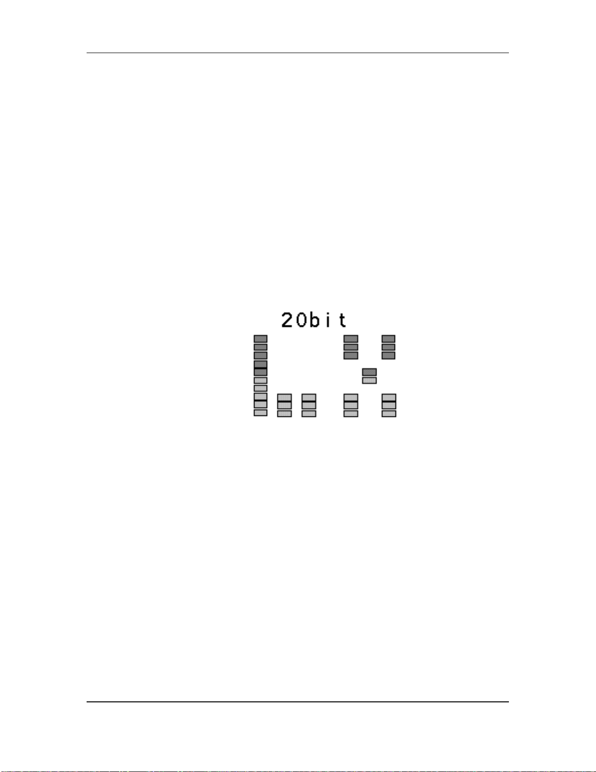
3. Select Audio
Resolution
20-bit gives the best fidelity. 16-bit is compatible with older, Type I-only ADAT or ADAT-XT.
Alesis recommends 20 bit resolution unless you are certain that the tape will play back only on a
Type I machine. If you need a 16-bit tape, you can always copy the 20-bit version to a 16-bit
format.
4. Initiate format
the CLOCK SELECT
button until the
display shows…
the FORMAT button
until the display
shows…
Hold RECORD,
then press PLAY (if
extending a format,
wait until the
display shows
“Locked” before
initiating format)
44.1 kHz, 48 kHz, or DIGital Audio Clock (44.1 or
48 kHz)
20-bit (best fidelity) or 16-bit (compatible with
older, Type I-only ADAT and ADAT-XT). The
RECORD LEDs for tracks 1 through 8 will
flash.
The LX20 records 15 seconds of leader (the LED
display shows “LEAd”), then 2 minutes of data
(the display says “dAtA”), then time code
starting at 0:00:00.00 and continuing to the end of
the tape.
If the tape was not completely rewound, the LX20 automatically rewinds to the beginning before
formatting.
ADAT LX20 Reference Manual 29
 Loading...