


 Loading...
ALESIS
1622 Mixer
Reference Manual
TABLE OF CONTENTS |
|
INTRODUCTION.................................................................................................................... |
2 |
WHAT IS A MIXING CONSOLE?............................................................................... |
2 |
FEATURES................................................................................................................ |
2 |
SECTION 1 |
|
DESCRIPTION OF CONTROLS ................................................................................ |
3 |
TOP PANEL .................................................................................................. |
3 |
INPUT TRIM ..................................................................................... |
3 |
EQ .................................................................................................... |
3 |
SENDS ............................................................................................. |
3 |
PRE-FADER SENDS............................................................ |
3 |
POST-FADER SENDS ......................................................... |
4 |
MASTER ASSIGN SWITCH ............................................................. |
5 |
SUB MASTER ASSIGN SWITCH ..................................................... |
5 |
MUTE SWITCH ................................................................................ |
6 |
SOLO SWITCH................................................................................. |
6 |
PAN POT.......................................................................................... |
6 |
CHANNEL FADER............................................................................ |
6 |
SEND MASTERS.............................................................................. |
6 |
TAPE/MONITOR SWITCH................................................................ |
6 |
MONITOR VOLUME ......................................................................... |
6 |
EFFECTS RETURNS ....................................................................... |
6 |
SUB MASTER FADERS ................................................................... |
7 |
SUB MASTER TO MASTER ASSIGN SWITCH................................ |
7 |
MASTER FADERS............................................................................ |
7 |
BACK PANEL................................................................................................ |
7 |
MIC/LINE INPUTS ............................................................................ |
7 |
MICROPHONE INPUTS ................................................................... |
7 |
DIRECT OUTPUTS........................................................................... |
7 |
CHANNEL INSERTS......................................................................... |
8 |
SENDS ............................................................................................. |
8 |
RETURNS ........................................................................................ |
8 |
HEADPHONE ................................................................................... |
8 |
SUB OUT.......................................................................................... |
8 |
SUB INSERT .................................................................................... |
8 |
MAIN OUT ........................................................................................ |
8 |
MAIN OUT LEVEL SELECTOR ........................................................ |
8 |
MAIN INSERT................................................................................... |
8 |
MONITOR OUT ................................................................................ |
8 |
POWER SUPPLY CONNECTOR...................................................... |
8 |
ON/OFF SWITCH ............................................................................. |
9 |
SIGNAL FLOW IN THE 1622 ..................................................................................... |
9 |
SECTION 2 |
|
SETTING UP THE 1622 ............................................................................................ |
12 |
CONNECTIONS TO THE MIXER .................................................................. |
12 |
INTERFACING TO A MULTITRACK TAPE RECORDER: |
|
4 TRACK THROUGH 8 TRACK RECORDING ..................... |
12 |
INTERFACING TO THE MULTITRACK TAPE RECORDER VIA A |
|
PATCHBAY ...................................................................................... |
13 |
INTERFACING THE 1622 MIXER TO THE MIXDOWN DECK.......... |
14 |
INTERFACING THE 1622 MIXER TO THE CONTROL ROOM |
|
MONITOR SPEAKERS..................................................................... |
15 |
INTERFACING THE 1622 MIXER TO A HEADPHONE AMP ............ |
15 |
INTERFACING THE SENDS AND RETURNS OF THE 1622 MIXER TO |
|
EFFECTS ......................................................................................... |
15 |
INSERT INTERFACING.................................................................... |
15 |
HOW TO ADJUST LEVELS .......................................................................... |
16 |
SECTION 3
APPLICATIONS ........................................................................................................ |
18 |
MULTITRACK RECORDING ......................................................................... |
18 |
INTRODUCTION TO MULTITRACK RECORDING........................... |
18 |
RECORDING ....................................................................... |
18 |
MONITORING ...................................................................... |
19 |
MULTITRACK MIX................................................... |
19 |
MONITOR SPEAKER (CONTROL ROOM) MIX....... |
19 |
CUE MIX.................................................................. |
19 |
MIXDOWN ........................................................................... |
19 |
THE 1622 MIXER AND A 4 OR 8 TRACK TAPE DECK................................. |
19 |
USING THE 1622 MIXER TO RECORD |
|
A SINGLE SOURCE TO 1 TRACK ....................................... |
20 |
TWO OR MORE SOURCES TO 1 TRACK........................... |
20 |
2 OR MORE SOURCES TO 2 TRACKS............................... |
20 |
RECORDING TIPS ........................................................................... |
21 |
HOW TO PLAYBACK FROM MULTITRACK..................................... |
21 |
HOW TO SET UP A CUE ................................................................. |
22 |
MIXDOWN........................................................................................ |
22 |
HOW TO CREATE A DEPENDABLE MIX........................................ |
23 |
HOW TO GROUP SEVERAL CHANNELS TOGETHER |
|
WHEN MIXING ................................................................................. |
25 |
HOW TO PLAYBACK A MIX FROM THE MIXDOWN TAPE DECK .. |
26 |
PLAYBACK TIPS.................................................................. |
26 |
SOUND REINFORCEMENT APPLICATIONS IN MONO .................. |
27 |
USING THE SUB MASTERS ............................................................ |
28 |
LINE INPUTS USED AS ADDITIONAL MIC INPUTS ........................ |
29 |
USING THE SUB MASTERS FOR SEPARATE OUTPUTS .............. |
29 |
STAGE MONITOR MIX FROM THE PRE-FADER SENDS ............... |
30 |
DEDICATED MIDI KEYBOARD MIXER......................................................... |
30 |
SECTION 4
TROUBLESHOOTING .............................................................................................. |
32 |
NO SOUND ................................................................................................... |
32 |
NO SOUND WHEN CHANNEL IS SOLOED ..................................... |
32 |
NO SOUND WHEN MONITOR LEVEL TURNED UP........................ |
32 |
OVERLOAD PROBLEMS .............................................................................. |
32 |
DISTORTION HEARD WHEN INPUT CHANNEL IS SOLOED.......... |
32 |
DISTORTION IS BEING RECORDED ONTO TAPE, BUT DISTORTION |
|
NOT HEARD WHEN INPUT CHANNEL IS SOLOED........................ |
33 |
DISTORTION AT MIXDOWN MACHINE OR SOUND SYSTEM ....... |
33 |
DISTORTION ON THE RETURNS.................................................... |
33 |
SECTION 5
GROUNDING............................................................................................................. |
33 |
SECTION 6 |
|
SPECIFICATIONS ................................................................................................................. |
35 |
GLOSSARY ........................................................................................................................... |
36 |
APPENDIX ............................................................................................................................. |
42 |
INDEX .................................................................................................................................... |
44 |
BLOCK DIAGRAM................................................................................ |
45 |
Alesis 1622
Monolithic/Integrated Surface™ Audio Console
USER'S MANUAL

Alesis 1622
Monolithic/Integrated Surface™ Audio Console
INTRODUCTION
The Alesis 1622 Monolithic/Integrated Surface™ Audio Console is a 16 channel, two buss audio mixing console which features the new Integrated Monolithic Surface™technology. This technology makes available a number of features at low cost which previously could only be found in much more expensive consoles .
The 1622 MIXER provides excellent sonic qualities, with extremely low noise and crosstalk, flat wideband frequency response, and the superb sweet sound normally associated with consoles costing many times more. Thus the 1622 MIXER can be used as an additional "Musical Tool" .
Because of the built-in flexibility of the 1622 MIXER, the unit is at home in any application, be it recording, sound reinforcement, post-production, or as a dedicated keyboard mixer.
WHAT IS A MIXING CONSOLE?
As the name implies, a mixing console "mixes" audio signals together from various sources (microphones, keyboards, tape machines, reverbs, etc.). But unlike a simple "mixer", a mixing console is really the "brain" or center of the entire sound system, regardless of the application, since it not only mixes the signals together, but also provides routing of these signals to tape recorders, effects devices, and other audio systems. The console also allows for adjustment of monitoring levels independent of recording levels.
FEATURES
•16 INPUT CHANNELS WITH EQ - Plenty of inputs for keyboards, microphones, or effects
•6 AUXILIARY SENDS - Sends signal to up to 6 outboard effects devices, or 4 outboard effects devices and 2 mono or 1 stereo headphone cue mixes
•8 AUXILIARY RETURNS - Special dedicated inputs designed to blend the returns of any combination of 8 mono or 4 stereo outboard effects devices
•SOLO FUNCTION ON INPUT CHANNELS - Enables any overloads or unwanted background noise to be easily detected
•2 SUB MASTERS - Makes it easy to control several input channels with just one fader (or two for stereo), or control record levels during multitrack recording
•CONTROL ROOM MONITOR SECTION - Sets a level for the control room monitor speakers that is independent of the main mix
•ELECTRONICALLY BALANCED MIC INPUTS - A feature normally found on consoles that are many times more expensive, this allows for both lower noise and greater headroom in the most critical stage of the console
•MIXDOWN TAPE DECK RETURN - Allows you to hear playback of your mix from the stereo mixdown tape machine just by flipping a switch
•INSERTS ON ALL INPUTS AND OUTPUTS - Allows for patching outboard signal processing devices such as EQ's, compressors, and effects directly into the signal path
•8 DIRECT OUTPUTS - Allows for the quietest operation by bypassing unused electronics and sending the channel signal directly to the input of a Multitrack Tape Machine
2

3
SECTION 1
DESCRIPTION OF CONTROLS
TOP PANEL
INPUT TRIM
The INPUT TRIM is a variable gain control that allows the preamp stage of the mixer to boost the level of a mic or line level signal being fed into the input. The input section of any mixer is the most critical due to the high gain required to amplify such a low level signal (such as that of a microphone) to a usable level. If the gain is set too high, a hot signal from a synthesizer or loud vocalist will cause the input stage to overload and distort. If the gain is set too low, additional gain must be added at some other point in the mixer (such as the faders) which could cause excessive background noise at the output.
EQ
The equalizer, or EQ, section consists of simple bass and treble controls similar to that of a guitar amp or home stereo. EQ allows for any tonal shaping that might be required by a signal. For the technically minded, these are known as shelving equalizers and have turnover points at 10KHz and 100Hz. This means that the maximum boost or cut begins from 10KHz (and 100Hz for the low frequency EQ) and maintains this "shelf" or plateau from 10KHz to 20KHz. The frequencies below 10KHz are also affected, but less and less so as the frequency of the signal gets further away from 10KHz. See Figure 1
FIGURE 1
HI AND LO SHELVING EQ OF THE 1622 MIXER |
|
SHELF |
|
100Hz |
10KHz |
+15dB |
+15dB |
0 dB |
0 dB |
-15dB |
-15dB |
Frequency |
|
SENDS
SENDS (sometimes called "Auxiliary Sends" or "Aux's") are adjustable feeds from the input channel that are used to send part of the signal to an outboard effect, like a reverb, delay, or chorus, or to set up a separate cue (headphone) mix for musicians headphones during recording and overdubbing. There are two different types of SENDS included in the 1622. These are:
PRE-FADER SENDS
SENDS 1 and 2 are derived from the signal path before the Channel Fader. This means that movements of the channel fader will have no effect on the amount of signal being sent to any equipment connected to these SENDS. For this reason, these auxiliary sends are normally used as cue sends (sends to headphones while recording) because any movement of the channel
4
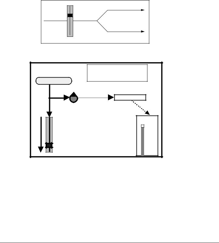
faders will not upset the headphone balance. Pre-Fader SENDS can also be used to send a signal to outboard effects as well. See Figure 2A and 2B
FIGURE 2A
PRE-FADER SEND LEVEL FROM THE 1622 MIXER TO EFFECTS DEVICE WITH CHANNEL FADER UP
|
PRE-FADER SEND |
INPUT |
SIGNAL |
FADER UP |
MASTER |
|
FIGURE 2B
PRE-FADER SEND LEVEL FROM THE 1622 TO EFFECTS DEVICE WITH CHANNEL FADER
|
B. PRE-FADER SEND |
|
|
WITH |
|
INSTRUMENT/MIC |
CHANNEL FADER DOWN |
|
|
||
PRE-FADER SEND |
||
|
EFFECTS DEVICE |
|
|
TO HEADPHONES |
|
|
OR EFFECTS |
|
|
INPUT |
|
|
LED METER |
|
CHANNEL |
+3 |
|
0VU |
||
FADER |
||
-10 |
||
|
||
|
-20 |
|
|
-30 |
|
|
-40 |
|
|
-50 |
|
|
-60 |
|
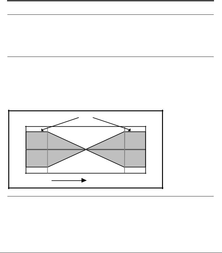
POST-FADER SENDS
SENDS 3 through 6 are derived from the signal path after the Channel Fader which means that their levels will be changed in direct relationship to the Channel Fader level. This means that when the Channel Fader is either increased or decreased, the send level will also be increased or decreased and the effects (or headphones) would get louder or softer. Since this wouldn't be too great for a headphone balance, these Post-Fader sends are normally used to send to outboard effects devices such as reverbs. Unlike most other mixers which may have only 1 or 2 Post-Fader Sends, the 1622 MIXER has a total of 4 Post-Fader Sends. See Figure 3A and 3B
FIGURE 3A
POST-FADER SEND LEVEL FROM THE 1622 MIXER TO EFFECTS DEVICE WITH CHANNEL FADER UP
5

|
A. POST-FADER SEND |
|
INSTRUMENT/MIC |
WITH |
|
|
CHANNEL FADER UP |
|
|
INPUT |
|
|
LED METER |
|
|
+3 |
|
|
0VU |
|
CHANNEL |
-10 |
|
-20 |
||
FADER |
||
-30 |
||
|
||
|
-40 |
|
|
-50 |
|
|
-60 |
|
POST-FADER SEND |
||
|
EFFECTS DEVICE |
|
|
TO HEADPHONES |
|
|
OR EFFECTS |
|
FIGURE 3B
POST-FADER SEND LEVEL FROM THE 1622 MIXER TO EFFECTS DEVICE WITH CHANNEL FADER DOWN
|
B. POST-FADER SEND |
|
INSTRUMENT/MIC |
WITH |
|
|
CHANNEL FADER DOWN |
|
|
INPUT |
|
|
LED METER |
|
|
+3 |
|
|
0VU |
|
CHANNEL |
-10 |
|
-20 |
||
FADER |
||
-30 |
||
|
||
|
-40 |
|
|
-50 |
|
|
-60 |
|
POST-FADER SEND |
||
|
EFFECTS DEVICE |
|
|
TO HEADPHONES |
|
|
OR EFFECTS |
|
MASTER ASSIGN SWITCH
Routes the channel signal directly to the MASTER Stereo Buss.
SUB MASTER ASSIGN SWITCH
Routes the channel signal directly to the SUB MASTER.
MUTE SWITCH
Turns the channel off. The MUTE switch does not affect the signal on SENDS1 and 2 but will mute SENDS 3 through 6.
SOLO SWITCH
6

SOLO disconnects the normal signal feed to the monitor speakers and replaces it with the signal present at the Channel Fader. When a channel is soloed, the signal will be heard in mono regardless of the position of the pan pot, and without any effects via the Sends and Returns.
Soloing enables the engineer to hear exactly what is being recorded by eliminating the masking effects caused by the presence of other signals. When soloed, distortion caused by overloading or other undesired background noises in an input channel can be heard easily.
SOLO switches can be used at any time without interrupting the signals sent to the headphones or recorded on tape since the soloed signal is only heard through the Monitor Speakers. By engaging additional SOLO switches, as many signals as desired can be soloed simultaneously.
PAN POT
The PAN POT places the signal of the channel anywhere in the stereo field between the left and right channels of the MASTER or SUB MASTERS (or both) depending upon which is assigned. If the PAN is set all the way to the left, the signal will appear only on the left SUB MASTER or MASTER fader. If the PAN is set all the way to the right, the signal will appear only on the right SUB MASTER or MASTER fader.
CHANNEL FADER
The CHANNEL FADER determines the overall volume level of the channel. It is normally best to keep this FADER at about the 3/4 level for the most headroom and least background noise.
SEND MASTERS 1 through 6
This is the overall master for the corresponding SEND of each channel. Therefore, if the level of SEND 1 was too hot and causing distortion, the overall level could be trimmed by adjusting SEND MASTER 1, which would lower the signal without having to individually adjust each channel SEND.
TAPE/MONITOR SWITCH
When the 1622 MIXER is used for recording, this switch will determine what you hear in the control room monitor speakers. When in the TAPE position, the signal from the Mixdown Tape Deck will be heard and can be adjusted from the MONITOR VOLUME pot. When in the MONITOR position, the signal from the console, as adjusted by the MASTER Faders and MONITOR VOLUME pot, will be heard.
MONITOR DEFEAT SWITCH
This switch will mute the signal going to the control room monitor speakers in the event that it is necessary to monitor with headphones via the headphone jack. This switch has no effect on the signals appearing at the MASTER Faders.
MONITOR VOLUME
The MONITOR VOLUME Control adjusts the volume level of the control room monitor speakers only. When the 1622 is used as a recording console, it is necessary to be able to control the level of the control room monitor speakers and the MASTER Fader output levels independently. Without the separate MONITOR VOLUME control, both the control room speakers and the mixdown tape level would be controlled by the MASTER Faders, which would cause either a distorted or noisy signal going to tape when the speaker levels were correct, or too loud or soft speaker levels when the tape machine levels were correct.
EFFECTS RETURNS
The EFFECTS RETURNS are additional inputs (besides the 16 Channel Inputs) especially for outboard effects such as reverbs, delays, chorus, etc. These inputs eliminate the need to connect effects to channel inputs and, therefore, keep the input channels available for additional microphones, synthesizers, etc.
There are 8 EFFECTS RETURNS on the 1622 MIXER . RETURNS 1 through 4 each have a PAN control which allows the the return signal to be placed anywhere in the stereo spectrum from left to right. RETURNS 5 and 7 are permanently assigned to the Left MASTER Buss, and RETURNS 6 and 8 are permanently assigned to the Right MASTER Buss.
SUB MASTER FADERS
7
The SUB MASTER Faders can serve several different functions, depending upon the application. In sound reinforcement or in recording during mixdown, the SUB MASTER Faders will act as a group master for a number of input channels. For instance, if Input Channels 1 through 8 contained drum mics, and you wanted to control the overall level of the drums with just one fader, this could be achieved by assigning input channels 1 through 8 to the SUB MASTER ASSIGN, and then panning each channel either hard left or hard right (for mono). The SUB MASTERS could also be assigned in stereo by panning the input channels to any point in the stereo spectrum, in which case the composite signal will appear on both the right and left SUB MASTER faders. See Section 3.
During recording, the SUB MASTERS can be used to mix several signals together onto a single track (or two tracks for stereo) by assigning those input channels to the SUB MASTERS and connecting the SUB OUT jack to the track that you wish to record on. See Section 3.
SUB MASTER TO MASTER ASSIGN SWITCH
This switch routes the signal on the SUB MASTERS to the MASTER Faders.
MASTER FADERS
The Left and Right MASTER Faders control the main output of the console to either the mixdown deck (in recording) or the sound system (in sound reinforcement).
MAIN STEREO METERS
The main STEREO METERS, each consisting of 7 green, 4 yellow, and 4 red LEDs, show the relative output levels of the MASTER Faders. The METERS will also show the level of any input channel that has its SOLO engaged.
SOLO/POWER LEDS
The SOLO LED lights whenever a solo is switched on. The POWER LED lights whenever AC power is connected to the unit.
BACK PANEL
MIC/LINE INPUTS
Channels 1 through 16 can be accessed via a 1/4" phone jack. Normally, this would be used for line level signals such as synthesizers or tape machines but it is also possible to feed a microphone signal into this jack. In 4 or 8 track recording applications, channels 9 through 16 would normally be used for tape returns of tracks 1 through 8, while channels 1 through 8 would be used for mic or instrument inputs.
MICROPHONE INPUTS
Channels 1 through 8 contain an XLR jack which provides an electronically balanced input ideally suited for a microphone. This input is overridden should a plug be inserted in the corresponding Input phone jack (XLR #1 is defeated if a phone plug is inserted in phone jack #1).
DIRECT OUTPUTS
Channels 1 through 8 contain a DIRECT OUTPUT jack. Each channel routes its own input signal, after it has been amplified and EQ'd, to the Direct Output jack. This is generally used to feed a single track of a Multitrack Tape Deck. Because the Direct Output is the path with the least amount of circuitry and therefore the lowest possible background noise, it is most desirable to use when recording the signal of only a single channel.
CHANNEL INSERTS
Channels 1 through 16 each contain a stereo jack called an INSERT. This consists of an insert send (the tip of a stereo phone plug) and insert return (the ring of a stereo phone plug) and is used to insert an outboard effects device, such as a compressor, EQ, or chorus, directly into the
8

signal path of only that channel. A special cable consisting of a single stereo 1/4" jack on one end and two mono 1/4" jacks on the other is required. See Section 2 - INSERT INTERFACING
SENDS
These jacks feed the signal from SEND MASTER 1 through 6 to an outboard effects device or headphone amplifier. SENDS 1 and 2 are derived Pre-Fader while SENDS 3 through 6 are derived Post-Fader.
RETURNS
The RETURN jacks are especially dedicated to the signals returning from any outboard effects devices back into the 1622 MIXER. RETURNS 1 through 4 are pannable between the Left and Right MASTER buss. RETURNS 5 and 7 are permanently assigned to the Left MASTER. RETURNS 6 and 8 are permanently assigned to the Right MASTER.
HEADPHONE
Controlled from the MONITOR VOLUME pot, the HEADPHONE jack provides substantial level to drive most headphones. It is not affected by the MONITOR DEFEAT switch.
SUB OUT
The outputs of the SUB MASTERS are available for connection to the inputs of a tape machine. In certain applications, such as video post production, the SUB OUTS may also have a different mix, such as a mix containing music and effects but minus the dialog, from the one available at the MAIN OUTPUTS.
SUB INSERT
A ring-tip-sleeve jack that allows insertion of an outboard effects device, such as a compressor like the Alesis MICRO LIMITER or reverb like a MICROVERB II, into the signal path of the SUB MASTER.
MAIN OUT
The outputs of the MAIN OUT are available for connection to the inputs of a Mixdown Tape Machine, sound system, or amplifier.
MAIN OUT LEVEL SELECTOR
This switch selects the proper level for use with either professional or semi-professional equipment. Select the +4dBV position (switch pressed in) for most sound systems and professional tape machines. Select the -10dBV position (switch out) for connection to guitar amplifiers or cassette decks. Generally speaking, use the -10dBV setting if you are connecting to a device that uses RCA jacks. Use the +4dBV setting for a device that uses XLR inputs. For a device that uses 1/4" phone jacks, try both settings and choose the one with the lowest background noise (hiss and hum).
MAIN INSERT
Allows for the insertion of an outboard effects device, such as the Alesis MICRO LIMITER or the Alesis QUADRAVERB, into the signal path of the MAIN Outputs.
MONITOR OUT
The outputs of the MONITOR OUT are available for connection to the inputs of the amplifier for the control room monitor speakers. The level is controlled by the MONITOR VOLUME pot.
TAPE INPUT
For connection of the output of a mixdown deck during recording. This will allow you to hear the playback of your mix without repatching.
POWER SUPPLY CONNECTOR
Connection for Alesis 1622 power supply.
9

ON/OFF SWITCH
Turns power on or off to the 1622. This should always be the first device turned on in the system and the last device turned off.
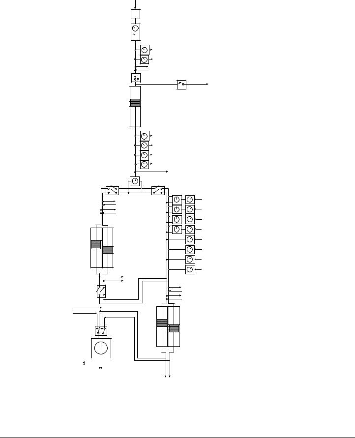
SIGNAL FLOW IN THE 1622
To help you better understand the way that the 1622 operates, the following is a Signal Flow Diagram of the complete signal path of the 1622.
FIGURE 4
1622 SIGNAL FLOW
10
Input
 Input Trim
 EQ Section
|
Aux Sends 1 - 2 |
|
(Pre-Fader Sends) |
Channel Insert |
|
Mute |
Solo |
to Solo Buss
Input Fader
|
|
Aux Sends 3 - 6 |
|
|
|
(Post - Fader Sends) |
|
|
Left/Right Pan |
Direct Out |
|
|
(Channels 1 - 8) |
||
|
Control |
||
|
|
||
Submaster |
|
Master Assign Switch (Channel) |
|
Assign Switch |
|
|
|
(Channel) |
|
|
|
|
Sub Inserts 1 - 2 |
|
|
|
|
Aux Returns 1 - 4 |
|
|
|
(Pannable) |
|
|
Sub Faders 1 - 2 |
|
|
|
|
Aux Returns 5 - 8 |
|
|
|
(Hardwired L - R) |
|
Sub Outs 1 -2 |
|
|
|
|
Submaster to |
|
|
|
Master Assign |
Master Inserts (L - R) |
|
From |
Switch |
||
|
|||
Mixdown |
|
|
|
Deck |
|
|
Tape/Line |
Master Faders (L - R) |
Monitor |
|
Switch |
|
|
Control |
|
Room |
|
Monitor |
|
Volume |
To |
|
|
|
|
|
|
|
|
|
|
|
||
Headphone |
|
Monitor |
||||
|
||||||
Jack |
|
|||||
|
Outputs |
|||||
|
|
|
|
|
||
|
|
|
|
|
(L - R) |
|
Master Outs (L - R)
Now, using the above Signal Flow Diagram, let's see what happens to a vocal as it goes from the input of a channel all the way to tape.
Starting at the top of the diagram, the signal from the mic enters the console through the channel's XLRInput jack. (As you'll remember, channels 1-8 have XLR jacks in addition to their unbalanced line ins. It is important to note that anything plugged into the line in jacks on
11

channels 1-8 will defeat the XLR jack for that channel). The signal is then boosted by the Input Trim to a level that the board can deal with easily. Now, you can adjust the tone of the singer's voice with the EQ Section, perhaps boosting the presence range a bit, or rolling off the low end to compensate for close miking. After you've done this, you can grab the signal viaAux Sends 1 - 2 and send it out of the first two Send jacks. Since these are Pre-Fader sends, the level of the signal going out of these jacks will not be affected when the input fader's level is adjusted. Because of this, they're perfect for setting up a cue mix, allowing the singer to hear the optimum blend of vocals, instruments, and effects.
Next comes the Channel Insert. This is a combination Send/Return accessed via the stereo Insert jack. Since the jack contains both the send and return, a special cable must be used, with the tip being used as the Send and the ring as the Return. Using the Channel Insert, we can smooth out the level of the vocal with a MICRO LIMITER before it goes to tape.
After the signal passes through the Input Fader, it can be sent out the other Send jacks via Aux Sends 3 - 6. Since these sends are taken from a point after the Input Fader, the level of the signal going out of them will be affected when you adjust the Input Fader. These sends are more suited to outboard effects like reverb, flanging, or delay. Later, when we mix down, we'll use these sends to set up a cool blend of QUADRAVERB and MICROVERB II to accentuate the performance.
Channels 1-8 each feature a Direct Out, which is generally used to feed a multitrack tape machine. The signal that is sent out of this jack is taken from the same point as the Post-Fader Sends. The vocal will then be sent through a Left/Right Pan Control, which determines its position in the stereo field relative to all of the other instruments and effects. We'll use this to set the vocal just a little off to the left of dead center in the mix, with the vocal effects panned a little right to make the vocal sound big and spacious. Then, depending on how the Submaster and Master Assign Switches are set, the vocal channel's signal is grouped with signal from other channels and sent to the submaster buss, the master buss, or both.
First off, let's say the Submaster Assign Switch is enabled. Before the vocal and the other instrument signals get to the faders that will determine their overall level, you have a chance to send them out of the board, effect them as a group, and return them back into the SubMaster buss using either of the Sub Inserts. We could use these to run all of the instruments through a single reverb for overall ambience. These inserts work along the same lines as the Channel Inserts. The only difference is that an effect inserted at this point will effect all of the channels that have been assigned to SubMaster 1 or 2 (depending on which insert you are using). Next, you'll set the overall level of the combined (and effected) signals withSub Faders 1 - 2, and the signal will then be sent out of the jacks marked Sub Outs 1-2.
Depending on how you're using the SubMaster busses, you may or may not want the grouped Sub signals to be routed into the Master buss. You can determine whether or not this will happen by enabling or disabling the SubMaster to Master Assign Switch.
Backing up a bit, let's say that our vocal channel'sMaster Assign Switch (just after the Pan Control) is enabled. These grouped signals will be sent through an insert/fader/output jack system similar to the one found on the SubMaster, but first they will be mixed with the aux returns. Aux Returns 1-4 are mono returns pannable to any point in the stereo field. This is where we'll control the level and panning of theQUADRAVERB/MICROVERB II effects blend on the vocal during mixdown. You can use one as a mono return, or you can group together two as a stereo return by panning them hard left and right. Aux Returns 5-8 are hardwired left and right as shown, providing two more pairs of stereo returns.
Next on the flow chart are the Master Inserts. These work the same as the Sub Inserts, but since the SubMasters feed into a point before the Master Inserts, any effect that is inserted into the Master Inserts will also effect the signal coming from the SubMasters (as long as the SubMaster to Master Assign switch is enabled).
Next are the Master Faders and Master Outs. The Faders set the overall level of the grouped signals in the Master buss, which are then sent to the Master Out jacks. This is where we'll do the
12
Loading...