


STEREO RECEIVER
RECEPTOR ESTEREO AMPLI-TUNER STEREO
AV-S17
OPERATING INSTRUCTIONS MANUAL DE INSTRUCCIONES MODE D’EMPLOI
En (English)
E (Español)
F (Français)
For assistance and information
call toll free 1-800-BUY-AIWA
(United States and Puerto Rico)
8A-AR5-903-01 000620CCK-Y-M
U

NOTE
This equipment has been tested and found to comply with the limits for a Class B digital device, pursuant to Part 15 of the FCC Rules.These limits are designed to provide reasonable protection against harmful interference in a residential installation.
This equipment generates, uses, and can radiate radio frequency energy and, if not installed and used in accordance with the instructions, may cause harmful interference to radio communications. However, there is no guarantee that interference will not occur in a particular installation. If this equipment does cause harmful interference to radio or television reception, which can be determined by turning the equipment off and on, the user is encouraged to try to correct the interference by one or more of the following measures:
-Reorient or relocate the receiving antenna.
-Increase the separation between the equipment and receiver.
-Connect the equipment into an outlet on circuit different from that to which the receiver is connected.
-Consult the dealer or an experienced radio/TV technician for help.
CAUTION
Modifications or adjustments to this product, which are not expressly approved by the manufacturer, may void the user’s right or authority to operate this product.
For assistance and information call toll free 1-800-BUY-AIWA (United States and Puerto Rico)
Printed in Malaysia
ENGLISH
WARNING
TO REDUCE THE RISK OF FIRE OR ELECTRIC SHOCK, DO NOT EXPOSE THIS APPLIANCE TO RAIN OR MOISTURE.
RISK OF ELECTRIC SHOCK
DO NOT OPEN
“CAUTION: TO REDUCE THE RISK OF
ELECTRIC SHOCK,
DO NOT REMOVE COVER (OR BACK). NO USER-SERVICEABLE PARTS INSIDE. REFER SERVICING TO QUALIFIED SERVICE PERSONNEL.”
Explanation of Graphical Symbols:
The lightning flash with arrowhead symbol, within an equilateral triangle, is intended to alert the user to the presence of uninsulated “dangerous voltage” within the product’s enclosure that may be of sufficient magnitude to constitute a risk of electric shock to persons.
The exclamation point within an equilateral triangle is intended to alert the user to the presence of important operating and maintenance (servicing) instructions in the literature accompanying the appliance.
Owner’s record
For your convenience, record the model number and serial number (you will find them on the rear of your unit) in the space provided below. Please refer to them when you contact your Aiwa dealer in case of difficulty.
Model No. |
Serial No. (Lot No.) |
AV-S17
PRECAUTIONS
Read the Operating Instructions carefully and completely before operating the unit. Be sure to keep the Operating Instructions for future reference. All warnings and cautions in the Operating Instructions and on the unit should be strictly followed, as well as the safety suggestions below.
Installation
1Water and moisture — Do not use this unit near water, such as near a bathtub, washbowl, swimming pool, or the like.
2Heat — Do not use this unit near heat sources, including heating vents, stoves, or other appliances that generate heat. It also should not be placed in temperatures less than 5°C (41°F) or higher than 35°C (95°F).
3Mounting surface — Place the unit on a flat, even surface.
4Ventilation — The unit should be situated with adequate space around it so that proper heat ventilation is assured. Allow 10 cm (4 in.) clearance from the rear and the top of the unit, and 5 cm (2 in.) from each side.
-Do not place the unit on a bed, rug, or similar surface that may block the ventilation openings.
-Do not install the unit in a bookcase, cabinet, or airtight rack where ventilation may be impeded.
5Objects and liquid entry — Take care that objects or liquids do not get inside the unit through the ventilation openings.
6Carts and stands — When placed or mounted on a stand or cart, the unit
should be moved with care.
Quick stops, excessive force, and uneven surfaces may cause the unit or cart to overturn or fall.
7Wall or ceiling mounting — The unit should not be mounted on a wall or ceiling, unless specified in the Operating Instructions.
Electric Power
1Power sources — Connect this unit only to power sources specified in the Operating Instructions, and as marked on the unit.
2Polarization — As a safety feature, some units are equipped with polarized AC power plugs which can only be inserted one way into a power outlet. If it is difficult or impossible to insert the AC power plug into an outlet, turn the plug over and try again. If it is not still inserted easily into the outlet, please call a qualified service technician to service or replace the outlet. To avoid defeating the safety feature of the polarized plug, do not force it into a power outlet.
3AC power cord
-When disconnecting the AC power cord, pull it out by the AC power plug. Do not pull the cord itself.
-Never handle the AC power plug with wet hands, as this could result in fire or shock.
-Power cords should be firmly secured to avoid being severely bent, pinched, or walked upon. Pay particular attention to the cord from the unit to the power socket.
-Avoid overloading AC outlets and extension cords beyond their capacity, as this could result in fire or shock.
4Extension cord — To help prevent electric shock, do not use a polarized AC power plug with an extension cord, receptacle, or other outlet unless the polarized plug can be completely inserted to prevent exposure of the blades of the plug.
5When not in use — Unplug the AC power cord from the AC power outlet if the unit will not be used for several months or more. When the cord is plugged in, a small amount of current continues to flow to the unit, even when the power is turned off.
1 ENGLISH
Outdoor Antenna
1Power lines — When connecting an outdoor antenna, make sure it is located away from power lines.
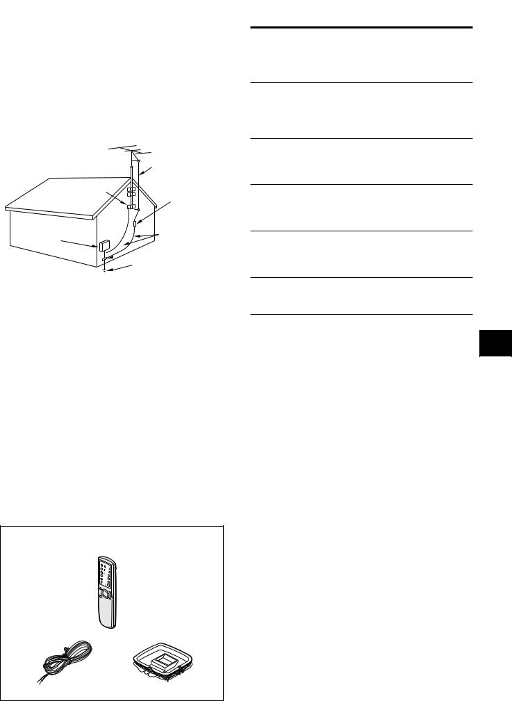
2Outdoor antenna grounding — Be sure the antenna system is properly grounded to provide protection against unexpected voltage surges or static electricity build-up. Article 810 of the National Electrical Code, ANSI/NFPA70, provides information on proper grounding of the mast, supporting structure, and the lead-in wire to the antenna discharge unit, as well as the size of the grounding unit, connection to grounding terminals, and requirements for grounding terminals themselves.
Antenna Grounding According to the National Electrical Code
|
ANTENNA LEAD IN WIRE |
GROUND CLAMP |
ANTENNA DISCHARGE |
UNIT |
|
|
(NEC SECTION 810-20) |
ELECTRIC |
GROUNDING |
SERVICE |
CONDUCTORS |
EQUIPMENT |
(NEC SECTION 810-21) |

 GROUND CLAMPS
POWER SERVICE GROUNDING ELECTRODE SYSTEM
(NEC ART 250 PART H)
NEC-NATIONAL ELECTRICAL CODE
Maintenance
Clean the unit only as recommended in the Operating Instructions.
Damage Requiring Service
Have the unit serviced by a qualified service technician if:
-The AC power cord or plug has been damaged
-Foreign objects or liquid have gotten inside the unit
-The unit has been exposed to rain or water
-The unit does not seem to operate normally
-The unit exhibits a marked change in performance
-The unit has been dropped, or the cabinet has been damaged DO NOT ATTEMPT TO SERVICE THE UNIT YOURSELF.
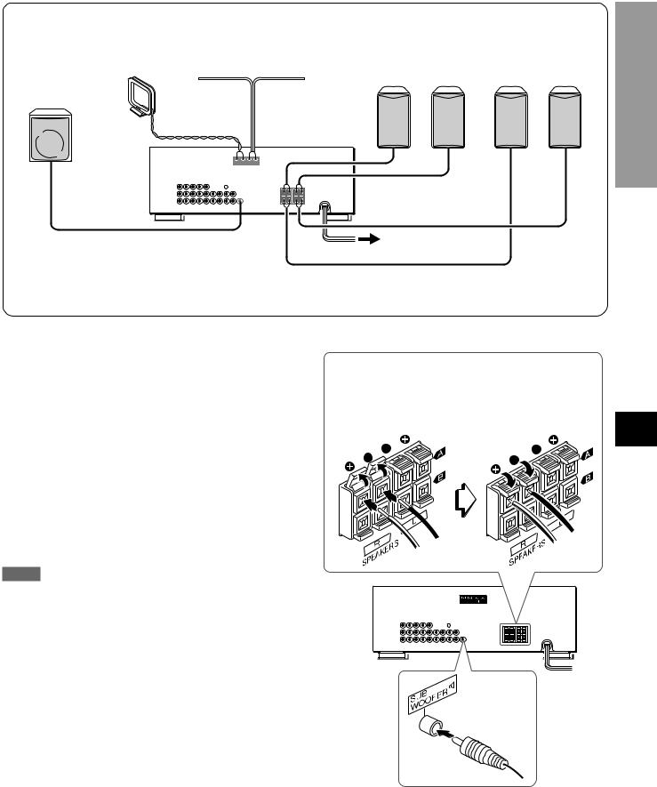
Check your accessories
Remote control
FM antenna |
AM antenna |
Operating Instructions, etc.
TABLE OF CONTENTS |
|
PRECAUTIONS ................................................................... |
1 |
PREPARATIONS |
|
CONNECTIONS .................................................................. |
3 |
SETTING THE CLOCK ........................................................ |
6 |
BEFORE OPERATION ........................................................ |
7 |
SOUND |
|
CUSTOM AUDIO ADJUSTMENT ....................................... |
8 |
ELECTRONIC GRAPHIC EQUALIZER .............................. |
9 |
BASIC OPERATIONS |
|
SELECTION OF AUDIO/VIDEO SOURCE ......................... |
9 |
RECORDING AN AUDIO SOURCE ................................. |
10 |
RADIO RECEPTION |
|
MANUAL TUNING ............................................................. |
11 |
PRESETTING STATIONS ................................................. |
12 |
TIMER |
|
SETTING THE SLEEP TIMER .......................................... |
12 |
GENERAL |
|
SPECIFICATIONS ............................................................. |
13 |
CARE AND MAINTENANCE ............................................ |
14 |
TROUBLESHOOTING GUIDE .......................................... |
14 |
PARTS INDEX ................................................................... |
14 |
En
E (Españ
F (Franç
ENGLISH 2

PREPARATIONS
CONNECTIONS
Before connecting the AC cord
The rated voltage of your unit shown on the rear panel is 120 V AC. Check that the rated voltage matches your local voltage.
IMPORTANT
Connect the speakers, antennas, and all other external equipment first. Then connect the AC cord at the end.
*1 Be sure to connect the VIDEO OUT terminal of a DVD player directly to a TV set, not through this unit. Otherwise, the picture noise may appear when playing copy protected DVDs.
*2 When connecting a monaural video, use a stereo-mono connecting cord (not supplied).
DVD or Video 1*2 /MD player
|
to AUDIO IN(Video 1/MD) |
|
to VIDEO IN(Video 1) |
o |
|
|
||
to AUDIO OUT |
|
o |
to VIDEO OUT(Video 1)*1 |
|
o |
|
|
|
to AUDIO OUT |
o |
Video 2*2 or
LD/Cable TV
o
to VIDEO OUT
to AUDIO IN (Video 2) |
o |
|
|
to VIDEO IN (Video 2) |
o |
|
CONNECTING EQUIPMENT
Jacks and plugs of the connecting cord are color-coded as follows:
Red jacks and plugs : For the right channel of audio signals White jacks and plugs: For the left channel of audio signals Yellow jacks and plugs: For video signals
NOTE
Insert the plugs fully into the jacks. Loose connections may produce a humming sound or other noise interference.
FRONT
Camcorder
 to VIDEO OUT
to AUDIO OUT
|
TV |
|
to VIDEO IN |
o |
to AUDIO OUTPUT |
|
REAR
o |
o |
|
|
o |
|
|
CD player |
o |
o |
|
o |
to OUTPUT |
|
|
|
|
|
|
Turntable |
to LINE IN |
to LINE OUT |
|
Tape deck |
|
3 ENGLISH
1 and 2 in the illustration correspond to the following details.
2AM antenna |
2FM antenna |
1Speaker system A |
1Speaker system B |
||
|
|
Right |
Left |
Right |
Left |
1Sub woofer
CONNECTING SPEAKERS1
Speaker terminals
Connect front speakers (system A and/or B) and sub woofer to the corresponding speaker terminals on the unit:
-the front speaker cords to the SPEAKERS terminals
-for more powerful bass, the sub woofer (with a built-in amplifier) cord to the SUB WOOFER 3 jack
Speaker impedance
For all speakers, use speakers of 8 ohms or more.
Connecting + to +, – to – terminals
To get the proper sound effect, the speaker terminals on the unit and the speaker should be connected with proper polarity; the + terminal on the unit should be connected to the + terminal on the speaker (and – to –).
NOTE
•The sub woofer sound will be output only when the speaker system A (the front speakers connected to the SPEAKERS A terminals) is selected.
•Be sure to connect the speaker cords correctly as shown in the illustration on the right column. Improper connections can cause short circuits in the SPEAKERS terminals.
•Do not leave objects generating magnetism near the speakers.
Lift up the terminal flap, insert the speaker cord lead into the terminal slot, then close the flap. Check that the cord is connected securely.
PREPARATIONS
En
E (Españ
F (Franç
ENGLISH 4
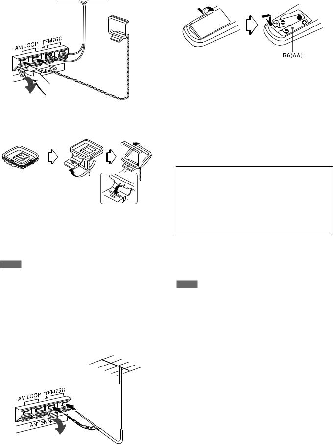
CONNECTING THE SUPPLIED ANTENNAS 2
Connect the FM antenna to the FM 75 Ω terminals and the AM antenna to the AM LOOP terminals.
FM antenna
AM antenna
To stand the AM loop antenna on a surface
Fix the claw to the slot as shown in the illustration.
To position the antennas
FM feeder antenna:
Extend this antenna horizontally in a T shape and fix its ends to the wall.
AM loop antenna:
Position for the best reception.
NOTE
•Do not bring the FM antenna near metal objects or curtain rails.
•Do not bring the AM antenna near other external equipment, the unit itself, the AC power cord or speaker cords, as noise will be picked up.
•Do not unwind the AM loop antenna wire.
CONNECTING AN OUTDOOR ANTENNA
For better FM reception, use of an outdoor antenna is recommended. Connect the outdoor antenna to the FM 75 Ω terminals.
ABOUT THE REMOTE CONTROL
Inserting batteries
Detach the battery cover on the rear of the remote control and insert two R6 (size AA) batteries.
When to replace the batteries
The maximum operational distance between the remote control and the sensor on the unit should be approximately 5 meters (16 feet). When this distance decreases, replace the batteries with new ones.
Using the remote control
The instructions in this manual refer mainly to the buttons on the main unit.
Some buttons have two functions.
•To use the function indicated on the button, or on the plate in black, simply press the button.
•To use the function indicated on the plate in green, press the button while pressing the SHIFT button.
Important
•The ENTER button on the remote control does not substitute for the ENTER button on the main unit. This button is for operating the DVD player only (see the next page.)
•In principal, the TUNING UP and DOWN buttons on the remote control substitute for N(TUNING UP) and M (TUNING DOWN) buttons on the main unit.
To select the function (audio source) with the remote control
Press the FUNCTION button repeatedly. The function changes cyclically.
NOTE
•If the unit is not going to be used for an extended period of time, remove the batteries to prevent possible electrolyte leakage.
•The remote control may not operate correctly when:
-The line of sight between the remote control and the remote sensor in the display window is exposed to intense light, such as direct sunlight.
-Other remote controls are used nearby (those of a television, etc.)
5 ENGLISH
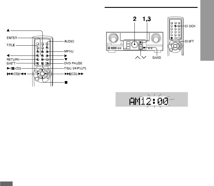
Operating AIWA CD or DVD players with the remote control
You can control the basic functions of AIWA CD or DVD players with the remote control. In principle, the buttons described below have the same function as those on the DVD or CD players.
For more details, refer to the operating instructions of the player.
Operating CD players
Press the following button.
c/a(CD) - Starts or pauses playback.
f,g - Searches a track. Hold the button down. r(CD),t(CD) - Skips a track. Press the button repeatedly. s - Stops playback.
DISC SKIP(CD) - Skips a disc in the CD changer.
Operating DVD players
Press the following button while pressing the SHIFT button. c - Starts playback.
f,g- Searches a track. s - Stops playback.
i,k,j,l(up, down, left or right) - Moves the cursor to select a program etc.
AUDIO - Changes an audio track (language etc.) ENTER - Enters the selected program etc.
TITLE or MENU - Enters the title or menu screen. RETURN - Returns to the previous mode etc. DVD PAUSE - Pauses the playback of a DVD.
NOTE
There are some AIWA COMPACT DISC PLAYERs for which some of the functions of the remote control do not work.
SETTING THE CLOCK
PREPARATIONS
When the AC cord is connected for the first time, the clock on the display flashes.
Set the time as follows while the power is off.
1 Press the ENTER button.
The display becomes a little brighter.
2 Within 4 seconds, turn the MULTI JOG to designate the hour and the minute.
The time advances by turning it to the right, and decreases |
|
||
by turning it to the left. |
|
||
The Nor Mbutton on the main unit is also available. Press |
|
||
the button repeatedly. To change the time rapidly in 10-minute |
En |
||
steps, hold it down. |
|||
3 Press the ENTER button. |
|
||
|
|||
The clock starts from 00 seconds. |
|
E (Españ |
|
|
|
|
|
NOTE |
|
|
|
|
|
|
|
When the clock is set for the first time after purchase |
|
|
|
Everything on the display will clear. |
|
F (Franç |
|
This is because the power economizing mode of the unit |
is |
||
activated, and is not a malfunction. |
|
|
|
The power economizing mode can be canceled. See page 7 |
for |
|
|
details. |
|
|
|
To correct the current time |
|
||
Press the POWER button to turn the unit off. Carry out steps 1 |
|
||
to 3 above. |
|
||
To display the current time |
|
||
Press the CLOCK button while pressing the SHIFT button on |
|
||
the remote control. The clock is displayed for 4 seconds. |
|
||
When the power is off in the power economizing mode, pressing |
|
||
the ENTER button on the unit also display the current time for 4 |
|
||
seconds. |
|
||
To switch to the 24-hour standard |
|
||
Display the current time, and press the BAND button on the unit |
|
||
within 4 seconds. |
|
||
Repeat the same procedure to restore the 12-hour standard. |
|
||
In the 12-hour standard, “AM 12:00” indicates midnight and “PM |
|
||
12:00” indicates noon. |
|
||
If the clock display flashes while the power is off |
|
||
This is caused by a power interruption. The current time needs |
|
||
to be reset. |
|
||
If power is interrupted for more than approximately 24 hours, all |
|
||
settings stored in memory after purchase need to be reset. |
|
||
ENGLISH 6
BEFORE OPERATION
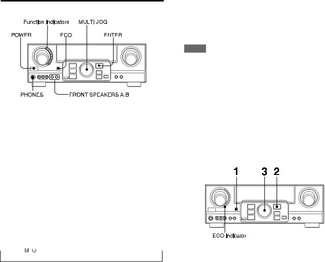
To turn the unit on
Press the POWER button.
Operation is possible after four seconds. The VOL (volume) level or function name is displayed one after the other for the first four seconds.
The selected function indicator lights up in red.
To change the brightness level of the display
1Press the ECO button repeatedly until “DIM MODE” is displayed.
2Within 4 seconds, press the ENTER button.
3Within 4 seconds, turn the MULTI JOG to select the dimmer mode as below.
The mode will be automatically set after 4 seconds. It will also be set if the ENTER button is pressed within 4 seconds after step 3.

 -
-


DIM-OFF: The normal display.
DIMMER 1: The illumination of the display is dimmer than usual.
DIMMER 2: The illumination of the display is dimmer than DIMMER 1. The function indicator turns off.
Using the headphones
Connect headphones to the PHONES jack with a standard stereo plug (ø 6.3 mm, 1/4 inch). Be sure to set the FRONT SPEAKERS A and B buttons to hOFF. Otherwise sound is output from the speakers.
To select the front speaker system
To use speaker system A: Set the FRONT SPEAKERS A button to HON.
To use speaker system B: Set the FRONT SPEAKERS B button to HON.
To use both speaker systems: Set both the buttons to HON. Set the button(s) to hOFF to turn off the speaker system(s).
NOTE
•As the front speaker systems A and B are connected in series:
-The sound will decrease slightly when using both speaker systems
-No sound can be heard if the FRONT SPEAKERS A and B buttons are set to HON when only one speaker system is connected
•The sub woofer sound will be output only when the speaker system A (the front speakers connected to the SPEAKERS A terminals) is selected.
To turn the unit off, press the POWER button.
POWER ECONOMIZING (ECO) MODE
Setting this unit to the ECO mode reduces power consumption as below.
Initial setting of the ECO mode is ON.
•When the current time is set, the clock display disappears immediately.
•While the power is off, all the display lights turn off, and only the ECO indicator lights in red.
To cancel the ECO mode
1Press the ECO button to display ECO MODE while the unit is turned on.
2Within 4 seconds, press the ENTER button.
3Within 4 seconds, turn the MULTI JOG to select ECO OFF. The mode will be automatically set after 4 seconds. It will also be set if the ENTER button is pressed within 4 seconds after step 3.
7 ENGLISH
 Loading...