


aiwa
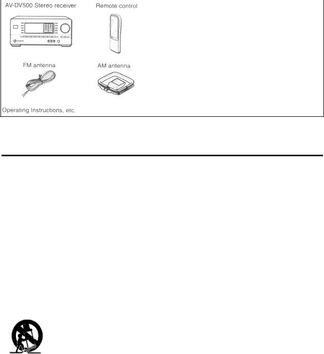
AV-DV500
STEREO RECEIVER
OPERATING INSTRUCTIONS
|
|
|
|
|
Precautions |
pg. 1 |
|
|
|
|
|
WARNING
To reduce the risk of fire or electric shock, do not expose this appliance to rain or moisture
"CAUTION: TO REDUCE THE RISK OF ELECTRIC SHOCK, DO NOT REMOVE COVER (OR BACK).
NO USER-SERVICABLE PARTS INSIDE. REFER TO QUALIFIED SERVICE PERSONNEL."
Explanation of Graphical Symbols:
The lightning flash with arrowhead symbol, within an equilateral triangle, is intended to alert the user to the presence of uninsulated "dangerous voltage" within the product's inclosure that may be of sufficient magnitude to constitute a risk of electric shock to persons.
The exclamation point within an equilateral triangle is intended to alert the user to the presence of important operating and maintenance (servicing) instructions in the literature accompanying the appliance.
Owner's record
For your convenience, record the model number and serial number (you will find them on the rear of your set) in the space provided below. Please refer to them when you contact your Aiwa dealer in case of difficulty.
Model No. |
Serial No. (Lot No.) |
AV-DV500
Check your unit and accessories
Precautions
Read the Operating Instructions carefully and completely before operating the unit. Be sure to keep the Operating Instructions for future reference. All warnings and cautions in the Operating Instructions and on the unit should be strictly followed, as well as the safety suggestions below.
Installation
1Water and moisture - Do not use this unit near water, such as near a bathtub, washbowl, swimming pool, or the like
2Heat - Do not use this unit near sources of heat, including heating vents, stoves, or other appliances that generate heat. It also should not be placed in temperatures less than 5ºC (41ºF) or greater than 35 Cº(95ºF).
3Mounting Surface - Place the unit on a flat, even surface
4Ventilation - The unit should be situated with adequate space around it so that proper heat ventilation is assured. Allow 10 cm (4 in.) clearance from the rear and then tope of the unit, and 5 cm (2 in.) from each side.
- Do not place the unit on a bed, rug, or similar surface that may block the ventilation openings.
- Do not install the unit in a bookcase, cabinet, or airtight rack where ventilation may be impeded.
5Objects and liquid entry - Take care that objects of liquids do not get inside the unit through the ventilation openings.
6Carts and stands - When placed or mounted on a stand or cart, the unit should be moved with care. Quick stops, excessive force, and uneven surfaces may cause the unit or cart to overturn or fall.
7Wall or ceiling mounting - The unit should not be mounted on a wall or ceiling, unless specified in the Operating Instructions
Electric Power
1Power sources - Connect this unit only to power sources specified in the Operating Instructions, and as marked on the unit.
2Polarization - As a safety feature, some units are equipped with polarized AC power plugs which can only be inserted one way into a power outlet. If it is difficult or impossible to insert the AC power plug into an outlet, turn the plug over and try again. If it still does not easily insert into the outlet, please call a qualified service technician to service or replace the outlet. To avoid defeating the safety feature of the polarized plug, do not force it into a power
outlet.
3 AC power cord
-When disconnecting the AC power cord, pull it out by the AC power plug. Do not pull the cord itself.
-Never handle the AC power plug with wet hands, as this could result in fire or shock.
-Power cords should be routed to avoid being severely bent, pinched, or walked upon. Pay particular attention to the cord from the unit to the power socket.
-Avoid overloading AC power plugs and extension cords beyond their capacity, as this could result in fire or shock. 4 Extension cord - To help prevent electric shock, do not use a polarized AC power plug with an extension cord, receptacle, or other outlet unless the polarized plug can be completely inserted to prevent exposure of the blades of the plug.
Precautions (cont.) pg. 2
pg. 2
5 When not in use - Unplug the AC power cord form the AC power plug if the unit will not be used for several months or more. When the cord is plugged in, a small amount of current continues to flow to the unit, even when the power is turned off.
Outdoor Antenna
1Power lines - When connecting an outdoor antenna, make sure it is located away from power lines.
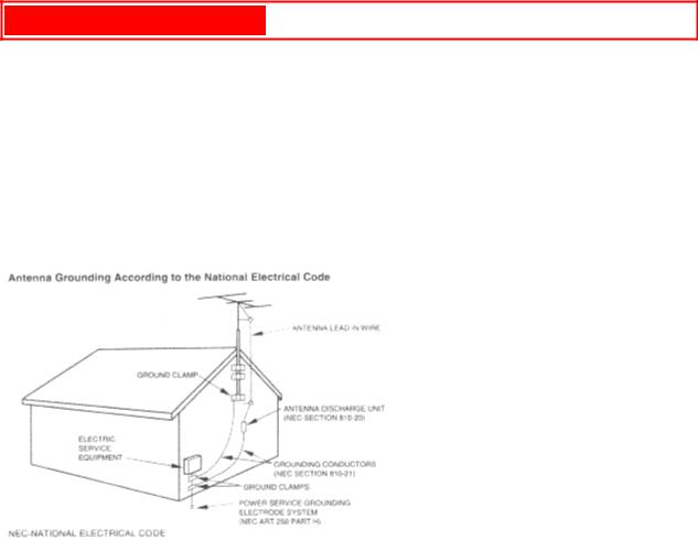
2Outdoor antenna grounding - Be sure the antenna system is properly grounded to provide protection against unexpected voltage surges or static electricity build-up. Article 810 of the National Electrical Code, ANSI/NFPA 70, provides information on proper grounding of the mast, supporting structure, and the lead-in wire to the antenna discharge unit, as well as the size of the grounding unit, connection to grounding terminals, and requirements for grounding terminals themselves.
Maintenance
Clean the unit only as recommended in the Operating Instructions
Damage Requiring Service
Have the units serviced by a qualified service technician if:
-The AC power cord or plug has been damaged
-Foreign objects or liquid have gotten inside the unit
-The unit has been exposed to rain or water
-The unit does not seem to operate normally
-The unit exhibits a marked change in performance
-The unit has been dropped, or the cabinet has been damaged
DO NOT ATTEMPT TO SERVICE THE UNIT YOURSELF
REMOTE CONTROL
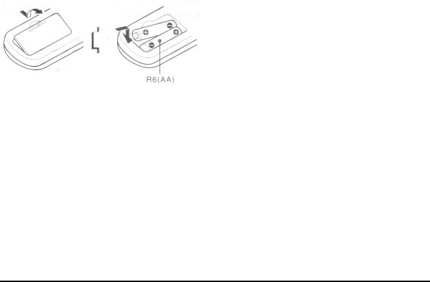
Inserting batteries
Detach the battery cover on the rear of the remote control and insert two R6 (size AA) batteries.
When to replace the batteries
The maximum operational distance between the remote control and the sensor on the main unit should be approximately 5 meters (16 feet). When this distance decreases, replace the batteries with new ones.
Using the remote control
The instructions in this manual refer mainly to the buttons on the main unit. Buttons on the remote control with the same names as those on the main unit can be used as well.
NOTE
•If the remote control is not going to be used for an extended period of time, remove the batteries to prevent possible electrolyte leakage.
•The remote control may not operate correctly when:
-The line of sight between the remote control and the remote sensor inside the display window is exposed to intense light, such as direct sunlight.
-Other remote controls are used nearby (those of a television, etc.
TABLE OF CONTENTS
PRECAUTIONS. . . . . . . . . . . . . . . . . . . . . . . . . . . . . . . . . . . . . . . . . . . . . . . . . . . . . . . . . 1
PREPARATIONS
CONNECTIONS. . . . . . . . . . . . . . . . . . . . . . . . . . . . . . . . . . . . . . . . . . . . . . . . . . . . . . . . .3 BEFORE OPERATION. . . . . . . . . . . . . . . . . . . . . . . . . . . . . . . . . . . . . . . . . . . . . . . . . . . .6 SETTING THE CLOCK. . . . . . . . . . . . . . . . . . . . . . . . . . . . . . . . . . . . . . . . . . . . . . . . . . .6
SOUND
CUSTOM AUDIO ADJUSTMENT. . . . . . . . . . . . . . . . . . . . . . . . . . . . . . . . . . . . . . . . . . 7 ELECTRONIC GRAPHIC EQUALIZER. . . . . . . . . . . . . . . . . . . . . . . . . . . . . . . . . . . . . .8 DSP SURROUND. . . . . . . . . . . . . . . . . . . . . . . . . . . . . . . . . . . . . . . . . . . . . . . . . . . . . . . .8
BASIC OPERATIONS
SELECTION OF AUDIO/VIDEO SOURCE. . . . . . . . . . . . . . . . . . . . . . . . . . . . . . . . . . . 9 RECORDING AN AUDIO SOURCE. . . . . . . . . . . . . . . . . . . . . . . . . . . . . . . . . . . . . . . . .9
RADIO RECEPTION
MANUAL TUNING. . . . . . . . . . . . . . . . . . . . . . . . . . . . . . . . . . . . . . . . . . . . . . . . . . . . . 10 DIRECT TUNING. . . . . . . . . . . . . . . . . . . . . . . . . . . . . . . . . . . . . . . . . . . . . . . . . . . . . . .10 PRESETTING STATIONS. . . . . . . . . . . . . . . . . . . . . . . . . . . . . . . . . . . . . . . . . . . . . . . .11
DOLBY PRO LOGIC
SELECTING DOLBY PRO LOGIC. . . . . . . . . . . . . . . . . . . . . . . . . . . . . . . . . . . . . . . . .12 ADJUSTING SPEAKER LEVEL BALANCE. . . . . . . . . . . . . . . . . . . . . . . . . . . . . . . . . 13
TIMER
SETTING THE SLEEP TIMER. . . . . . . . . . . . . . . . . . . . . . . . . . . . . . . . . . . . . . . . . . . . 14
GENERAL
CARE AND MAINTENANCE. . . . . . . . . . . . . . . . . . . . . . . . . . . . . . . . . . . . . . . . . . . . .14 SPECIFICATIONS. . . . . . . . . . . . . . . . . . . . . . . . . . . . . . . . . . . . . . . . . . . . . . . . . . . . . . 15 TROUBLESHOOTING GUIDE. . . . . . . . . . . . . . . . . . . . . . . . . . . . . . . . . . . . . . . . . . . .16 PARTS INDEX. . . . . . . . . . . . . . . . . . . . . . . . . . . . . . . . . . . . . . . . . . . . . . . . . . . . . . . . .16
PREPARATIONS pg. 3
CONNECTIONS
Before connecting the AC cord
The rated voltage of your unit shown on the rear panels is 120 V AC. Check that the rated voltage matches your local voltage.
IMPORTANT
Connect the speakers, antennas, and all other external equipment first. Then connect the AC cord at the end.
CONNECTING EQUIPMENT
Jacks and plugs of the connecting cord are color-coded as follows:
Red jacks and plugs: For the right channel of audio signals
White jacks and plugs: For the left channel of audio signals
Yellow jacks and plugs: For video signals
NOTE
Insert the plugs fully into the jacks. Loose connections may produce a humming sound or other noise interference.
click for image of connections
PREPARATIONS (cont.) pg. 4
pg. 4
CONNECTING SPEAKERS (1)
Speaker Terminals
Connect front speakers (system A and/or B), a center speaker and surround speakers to the corresponding speaker terminals on the unit:
-the front speaker cords to the FRONT SPEAKERS terminals
-the center speaker cord to the CENTER SPEAKER terminals
-the surround speaker cords to the SURROUND SPEAKERS terminals.
For more powerful bass, connect a sub woofer with a built-in amplifier to the SUPER WOOFER jack.
Speaker Impedance
• Front and center speakers
The SPEAKER IMPEDANCE SELECTOR on the rear should be set to the position that matches the impedance value of the front and center speakers.
When using 4 ohm speakers, set the selector to 4Ω. When using 8 ohm speakers, set the selector to 8 Ω. Please

unplug the AC cord before setting the selector.
• Surround speakers and super woofer
The SPEAKER IMPEDANCE SELECTOR has no effect on the SURROUND SPEAKERS terminals and the SUPER WOOFER jack. For the surround speakers and sub woofer, use speakers of 8 ohms or more.
Connecting + to +, - to - terminals
To get the proper sound effect, the speaker terminals on the unit and the speaker should be connected with proper polarity; the + terminal on the unit should be connected to the + terminal on the speaker (and - to -)
NOTE
•Be sure to connect the speaker cords correctly as shown in the illustration on the right column. Improper connections can cause short circuits in the SPEAKER (S) terminals.
•Do not leave objects generating magnetism near the speakers.
•When using a sub woofer, select the speaker system A (see page 6). Otherwise no sound can be heard from it.

POSITIONING THE SPEAKERS
Position the speakers to make the most of the Dolby Pro Logic or DSP effect (see "DOLBY LOGIC")
a)Front speakers
b)Center speaker
Position in the center of the two front speakers. In addition, position on or below the TV set, if connecting a TV set to the unit.
c) Surround Speakers
Place the surround speakers directly to the side of or slightly behind the listening area. Align them horizontally,
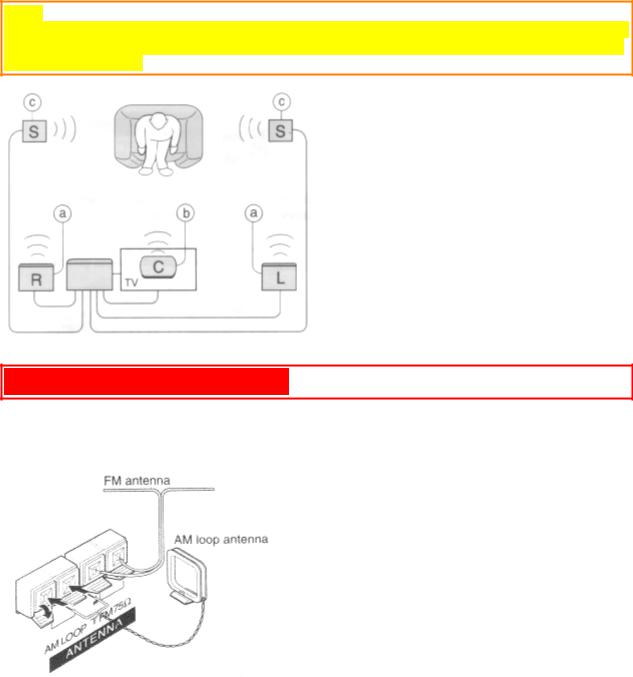
about 1 meter (3.2 feet) above ear height.
NOTE
Sound is heard from the center speaker mainly when the 5 CH surround or DOLBY PRO LOGIC is set on. Note that when you select the PHANTOM mode of the DOLBY PROG LOGIC, the center speaker is muted. (For details, see "DOLBY PRO LOGIC").
PREPARATIONS (cont.) pg. 5
pg. 5
CONNECTING THE SUPPLIED ANTENNAS (2)
Connect the FM antenna to the FM 75 Ω terminals and the AM antenna to the AM LOOP terminals.
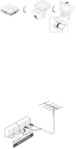
To stand the AM loop antenna on a surface
Fix the claw to the slot as shown in the illustration.
To position the antennas
FM feeder antenna:
Extend this antenna horizontally in a T shape and fix its ends to the wall.
AM loop antenna:
Position for the best reception.
NOTE
•Do not bring the FM antenna near metal objects or curtain rails.
•Do not bring the AM antenna near other external equipment, the unit itself, the AC power cord or speaker cords, as noise will be picked up.
•Do not unwind the AM loop antenna wire.
CONNECTING AN OUTDOOR ANTENNA
For better FM reception, use of an outdoor antenna is recommended. Connect the outdoor antenna to the FM ohm terminals.
TO CONNECT THE AIWA DVD PLAYER XD-DV500
Connect the output terminals of the DVD player to the input terminals of the receiver as follows:
 Loading...