


 Loading...
User Manual
Protect 2.33 2.0
|
|
Uninterruptible |
|
EN |
|
|
|
Power Supply UPS |
|
|
|
|
|
|
|
|
|
|
|
|
|
|
|
|
|
|
|
|
|
|
|
|
|
|
|
|
|
|
|
|
|
|
|
|
|
|
|

2
contents
1. Introduction........................................................................................ |
5 |
1.1. Using this manual.............................................................................................. |
5 |
1.1.1. Symbols and conventions used.................................................................... |
6 |
1.1.2. For more information and help............................................................... |
7 |
1.1.3. Safety and instructions............................................................................. |
7 |
2. Quality and standard guarantee........................................................ |
8 |
2.1. Management declaration................................................................................. |
8 |
2.2. Standards.......................................................................................................... |
9 |
2.3. Environmental protection................................................................................. |
9 |
3. Presentation..................................................................................... |
10 |
3.1. Views................................................................................................................ |
10 |
3.1.1. Views of the equipment......................................................................... |
10 |
3.1.2 Corresponding legends for the equipment views..................................... |
13 |
3.2. Structure.......................................................................................................... |
15 |
3.2.1. Structural schema................................................................................... |
15 |
3.3. Operating principle........................................................................................ |
15 |
3.3.1. Normal operation .............................................................................. |
16 |
3.3.2. Operation with mains failure ............................................................. |
16 |
3.3.3. Operation with inverter not active ................................................... |
16 |
3.3.4. Operation in manual bypass ............................................................ |
17 |
3.4. Parallel operation............................................................................................ |
17 |
4. Installation........................................................................................ |
19 |
4.1. Important safety instructions.......................................................................... |
19 |
4.1.1. Battery safety instructions...................................................................... |
20 |
4.1.2. Cabinet access....................................................................................... |
21 |
4.2. Set up and installation.................................................................................... |
23 |
4.2.1. Unpacking and content checking......................................................... |
23 |
4.2.2. Storage................................................................................................... |
24 |
4.2.3. Transportation to site............................................................................. |
24 |
4.2.4. Location.................................................................................................. |
25 |

3
4.3. Connection...................................................................................................... |
26 |
4.3.1. To the mains connection, terminals (X1 to X4)..................................... |
26 |
4.3.2. Connection of the output, terminals (X6 to X9)................................... |
28 |
4.3.3. UPS connection to each battery pack in cabinet, |
|
terminals (X11, X12, X23 and X47, X48, X49)...................................... |
29 |
4.3.4. Connection main protective earthing terminal ( ) |
|
and protective earth bonding terminal ( )........................................ |
30 |
4.3.5. Interface relay contacts, connector (X32)............................................. |
30 |
4.3.6. COM-interface RS232 and RS485, connector (X31)............................ |
31 |
4.3.7. EPO terminals (X50)............................................................................... |
33 |
4.3.8 Parallel BUS connection (X36)................................................................ |
33 |
5. Operation......................................................................................... |
35 |
5.1. Start up............................................................................................................ |
35 |
5.1.1. Control before start up.......................................................................... |
35 |
5.1.2. Start up procedure................................................................................. |
35 |
5.2. Complete UPS shutdown............................................................................... |
37 |
5.3. Emergency power off (EPO) operation......................................................... |
38 |
5.4. Bypass manual switch (Maintenance)............................................................ |
38 |
5.4.1. Principle of operation............................................................................ |
38 |
5.4.2. Transfer to maintenance bypass............................................................ |
38 |
5.4.3. Transfer to normal operation................................................................. |
39 |
6. Control panel and display description............................................. |
41 |
6.1. Control panel parts......................................................................................... |
41 |
6.1.1. Touch Screen.......................................................................................... |
41 |
6.2. Basic functions of keyboard from synoptic................................................... |
41 |
6.2.1. Messages menus and classification in submenus................................... |
43 |
6.2.2. Menu structure....................................................................................... |
44 |
6.3. Screen description.......................................................................................... |
45 |
6.3.1. Main level (screen menu 0.0)................................................................. |
45 |
6.3.2. UPS status control (screen menu 1.0)................................................... |
46 |
4
6.3.3. ‘‘MEASURES” level (screen menu 2.0).................................................... |
48 |
6.3.4. ‘‘SETTINGS” level (screen menu 3.0)..................................................... |
51 |
6.3.5. ‘‘ALARMS” level (screen menu 4.0)....................................................... |
56 |
6.3.6. ‘‘DATA LOGGER” level (screen menu 5.0)........................................... |
69 |
7. Maintenance, warranty and service................................................. |
71 |
7.1. Basic maintenance guide............................................................................... |
71 |
7.1.1. Battery fuses........................................................................................... |
71 |
7.1.2. Batteries.................................................................................................. |
71 |
7.1.3. Cooling Fan............................................................................................ |
72 |
7.1.4. Capacitors............................................................................................... |
72 |
7.2. Warranty conditions........................................................................................ |
72 |
8. Annexes............................................................................................ |
73 |
8.1. General technical Specification...................................................................... |
73 |
8.2 Safety Instructions............................................................................................ |
76 |
5
1. Introduction
We would like to thank you in advance for the trust you have placed in us by purchasing this product. Read this instruction manual carefully before starting up the equipment and keep it for any possible future consultation that may be required.
We remain completely at your disposal for any further information or any query you should wish to make.
Yours sincerely, AEG Power Solutions
•The equipment here described can cause significant physical damage due to improper handling. This is why the installation, maintenance and/or fixing of the equipment described here must be done by our staff or specifically authorised personnel.
•According to our policy of constant evolution, we reserve the right to modify the specifications in part or in whole without advance warning.
•All reproduction or third party concession of this manual is prohibited without the previous written authorization of our firm.
1.1. Using this manual
The goal of this manual is to give explanations and procedures for the installation and operation of the equipment. This manual has to be read carefully before instaling and operating the equipment. Keep this manual for future consultation.
This equipment has to be installed by qualified staff. With the simple help of this manual, it can be operated by personnel without specific training.

6
1.1.1. Symbols and conventions used
Warning
Carefully read the indicated paragraph and take the stated prevention measures.
Danger of electrical discharge
Pay special attention to it, both in the indication on the equipment and in the paragraph referred in this user manual.
Main protective earthing terminal
Connect the earth cable coming from the installation to this terminal.
Earth bonding terminal
Connect the earth cable coming from the installation to this terminal.
Notes of information
Additional topics that complement the basic procedures.
Preservation of the environment
The presence of this symbol in the product or in its associated documentation states that, when its useful life is expired, it will not be disposed with the domestic refuse. In order to avoid possible harm to the environment, separate this product from other refuse and recycle it appropriately. Users may contact their provider or with the relevant local authorities to be informed on how and where they can take the product to be recycled and/or disposed of correctly.
7
1.1.2. For more information and help
For more information and/or help with the version of your specific unit, contact our Service and Technical Support (S.T.S.).
1.1.3. Safety and instructions
Together with the equipment and this “user and installation“ manual, information pertaining to “safety instructions” is provided. These can be found in chapter 8.2 of this manual. Before proceeding to installation or commissioning, check that both sets of information are available. Please refer to chapter 8.2 carefully. Compliance with “safety instructions” are available for you to understand and observe. Once read, keep the safety instructions available for future reference.

8
2. Quality and standard guarantee
2.1. Management declaration
Our goal is the client’s satisfaction, therefore this management has decided to establish a quality and environmental policy, by means of installation a quality and environmental management system that becomes us capable to comply the requirements demanded by the standard ISO 9001 and ISO 14001 and by our clients and concerned parts too.
Likewise, the enterprise management is committed to the development and improvement of the quality and environmental management system, through:
•The communication to all the company about the importance of satisfaction both in the client’s requirements and in the legal regulations.
•Publicizing the quality and environmental policy diffusion and meeting the quality and environment targets.
•To carry out revisions by the management.
•To provide the needed resources.
Quality and environmental officer
The management designated person in charge of the quality and environment department, who, independent of other responsibilities, has the responsibility and authority to assure that the processes of the quality and environmental management systems are established and maintained; to inform the management about the operation of the quality and environmental management system, including areas for improvement; and to promote the knowledge of the requirements and environmental requirements at all levels of the organization.
The following process map represents the interaction among all the processes of the quality and environmental system:
CONTINUOUS IMPROVEMENT PROCEDURE / MANAGEMENT REVISION
QUALITY MANAGEMENT PROCESS  ENVIRONMENT MANAGEMENT PROCESS
R & D PROCESS |
TECHNICAL OFFICE PROCESS |
CLIENT: |
CLIENTS |
|
- PRODUCT |
COMMERCIAL PROCESS |
PRODUCTION PROCESS |
- SERVICE |
|
INTERNAL LOGISTICS PROCESS
MAINTENANCE PROCESS
TRAINING PROCESS
Fig.1: Process map of quality and environmental system.
9
2.2. Standards
The UPS series product is designed, manufactured and certified in accordance with the standard ISO 9001 of quality management systems. The marking shows the conformity to the EEC directive (quoted between brackets) by means of the application of the following standards:
•2006/95/EC: Low voltage directive.
•2004/108/EC: Electromagnetic Compatibility directive (EMC)
In accordance with the specifications of the harmonized standards:
•EN-IEC 62040-1: Uninterruptible power supply (UPS). Part 1-1: General and safety requirements for UPSs used in accessible areas by end users.
•EN-IEC 60950-1: IT equipment. Safety. Part 1: General requirements.
•EN-IEC 62040-2: Uninterruptible power supply (UPS). Part 2: Prescriptions for Electromagnetic compatibility (EMC).
•EN-IEC 62040-3: Uninterruptible power supply (UPS). Part 3: Methods of operation specification and test requirements.
The manufacturer’s responsibility is excluded in the event of any modification or tampering with the product on the customer’s side.
2.3. Environmental protection
This product has been designed to respect the environment and has been manufactured in accordance with the standard ISO 14001.
Equipment recycling at the end of its useful life:
Our company is committed to use the services of authorised institutions and according to the regulations to safely dispose of the recovered product at the end of its useful life (contact your distributor).
•Packing: To recycle the packaging, follow the legal regulations in force.
•Batteries: The batteries pose a serious danger for health and the environment. The disposal of them must be carried out in accordance with the standards
in force.

10
3.Presentation
3.1.Views
3.1.1. Views of the equipment
(fig. 4) 


 (RV)
(RV) 

 (fig. 4)


(RV) 


 (RV)
(RV)
(CL)

(CL) 


 (PF)
(PF)  (PF)
(PF) 


(PB) |
(PB) |
|
(RD) (RD) |
||
|
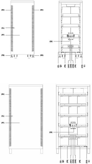
Fig.2: Cabinet front view for UPS up to 20 kVA with front door closed
Fig.3: Cabinet front view for UPS from 30 to 80 kVA with front door closed
11
|
|
a |
|
|
b |
2 |
1 |
c |
|
|
d |
|
|
e |
|
3 |
|
Fig.4: Control panel view |
Fig.5: Communication connectors details |
*Not available for Protect 2.33 2.0
Fig.6: Cabinet front view for UPS up to 20 kVA with front door opened
Fig.7: Cabinet front view for UPS up to 30 to 80 kVA with front door opened
12
Fig.8: No. 1–3 battery cabinet front view with front door closed
Fig.9: No. 1–3 battery cabinet front view with front door opened
Fig.10: No. 4 battery cabinet front view with front door closed
Fig.11: No. 4 battery cabinet front view with front door opened

13
3.1.2 Corresponding legends for the equipment views
Protection and handling elements (Q):
(Q1a) Input circuit breaker or switch according to power of the equipment (Q2) Output switch
(Q3) Battery fuse holder switch with 3 fuses (models up to 40 kVA) or switch (for higher models)
(Q4) Not available for Protect 2.33 2.0
(Q5) Maintenance bypass switch
(Q8) Battery fuse holder switch 3 fuses, located in the battery cabinet
Connecting elements (X): (X1) Phase input terminal R (X2) Phase input terminal S (X3) Phase input terminal T (X4) Neutral input terminal N
(X5) Main protection earthing terminal ( ) (X6) Phase output terminal U
(X7) Phase output terminal V
(X8) Phase output terminal W
(X9) Neutral output terminal N
(X10) Earth bonding terminal for load or loads and/or battery cabinet ( ) (X11) Battery terminal +
(X12) Battery terminal –
(X23) Battery terminal N
(X31) DB9 connector COM RS232and RS485 ports
(X32) DB9 connector relay interface
(X36) Connector for connecting cable for parallel use
(X47) Battery terminal + of external batteries cabinet
(X48) Battery terminal – of external batteries cabinet
(X49) Battery terminal N (middle tap) of external batteries cabinet (X50) Terminals for external EPO
14
Keyboard and optical indications control panel (PC):
(LCD) |
Graphic LCD |
(ENT) |
Key “ENTER” |
(ESC) |
Key “ESC” |
() |
Key up |
() |
Key down |
() |
Key move to right |
() |
Key move to left |
(a)Rectifier input voltage OK led (green)
(b)Output voltage unit from the bypass LED (orange)
(c)Inverter is working led (green)
(d)Unit working from batteries - mains failure - LED (red)
(e)General alarm. In case of any alarm of the unit LED (red)
Other abbreviations:
(BL) Mechanical block for manual bypass switch (Q5) (CL) Lock for cabinet front door
(PB) Levelers and immobilizing elements (PC) Control panel
(PF) Cabinet front door
(PR) Cable routing or wire cones (RD) Scroll wheel
(RV) Ventilation grille
(SL) Slot for optional intelligent card (TB) Terminal cover
(TS) Slot cover (SL)
(t1) Screws fixing for terminals cover (TB)
(t2) Screws fixing for mechanical block (BL) for switch (Q5) (t3) Screws fixing for slot cover (TS)
15
3.2. Structure
3.2.1. Structural schema
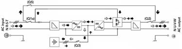
In a single line diagram, figure 12 shows the basic structure of standard equipment and another one with separate bypass line, for a three phase input and output configuration. For any other configuration, only the quantity of cables and terminals at the input, output and bypass will vary. The internal structure of the equipment will never vary.
Maintenance line (manual bypass).
Emergency line (static bypass)
Normal operation Mains failure
Inverter operation not active (provided that the EPO inactive)
Operation on bypass manual
Fig.12: UPS block diagram with operating flows
3.3. Operating principle
Protect 2.33 2.0 is a double conversion system AC/DC, DC/AC with a sine wave output that gives safe protection in extreme conditions of power supply (variations in voltage, frequency, electrical noises, blackout and other power disturbances, etc…). Whatever the kind of load that has to be protected, these devices are prepared to assure quality and continuity in the electrical supply.
The operation is basically as follows:
•Rectifier, an IGBT three phase rectifier, converts the AC voltage into DC by absorbing a pure sine wave current (THD < 2,5 %*), and charging batteries at constant current / voltage.
•The batteries supply the power needed by the inverter in the event of mains failure.
•The inverter deals with transforming the voltage of the DC bus into AC by providing a sine wave, alternating output stabilized in voltage and frequency suitable for supplying the loads connected on the output.
*from 50 % load
16
•The basic double conversion structure is complemented by two new functional blocks, the static bypass commuter switch and the manual bypass commuter switch.
•The static bypass commuter switch connects the output load directly to the bypass network in special circumstances such as overloading or overheating and reconnects it to the inverter when normal conditions are restored.
•The manual bypass commuter switch isolates the UPS from the mains and from the loads connected on the output, so that maintenance operations may be performed in the UPS without any need to interrupt the supply to the loads.
3.3.1.Normal operation 
With the mains present, the rectifier transforms the AC input voltage into DC, raising the DC voltage to a suitable level for supplying the inverter and to charge the batteries.
The inverter deals with transforming the voltage of the DC bus into AC, providing a sine wave alternating output, stabilized in voltage and frequency to supply the loads connected to the output (Fig.12).
3.3.2. Operation with mains failure 
In the event of mains failure or power disturbance occur, the group of batteries supplies the power needed to supply the inverter.
The inverter continues working normally, independent of the lack of mains, and the back-up time of the device depends only on the capacity of the group of batteries (Fig.12).
When the battery voltage reaches the end of back-up time, the control blocks the output as protection against a deep battery discharge.
When the mains returns and following the first seconds of analysis, the UPS operates once more as in section “Normal operation”.
3.3.3. Operation with inverter not active 
The inverter is inactive due to the existence of alarm conditions such as overloads, overheating, end of back-up time, etc. In this case the rectifier continues charging the batteries to maintain their optimal charge state.
The inverter is also inactive if the unit has not been started up with the keyboard. In this case, the rectifier will be inactive.
17
In all these cases the output voltage of the UPS is supplied by the emergency bypass line through the static bypass commuter switch (Fig. 12), provided that the EPO is inactive.
3.3.4. Operation in manual bypass 
When we wish to perform some maintenance check on the device, it may be disconnected from the mains without any need to cut the power supply to the system and affect the critical load. The UPS may be altered, only by technical or maintenance personnel. For maintenance bypass follow the special instructions for that purpose (refer chapter 5.4).
3.4. Parallel operation
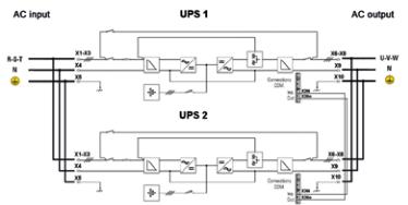
Fig.13: Single line diagram for UPS parallel system
2 UPS’s can be paralleled to one UPS system for redundancy purposes or to double the maximal load level. Only identical UPS with the same ratings can be paralleled. Fig.13 shows the single line diagram of a parallel system of Protect 2.33 2.0 showing the power connections and the control bus cables. Two UPS running in parallel always do load-sharing. Parallel operation offers several advantages like higher availability or “modular” adaption of the UPS system to cover increasing power demands.
The parallel system management is based on a dynamic MASTER-SLAVE principle, where the first UPS in normal operating mode will become MASTER. It has the control of the second UPS (SLAVE).
18
There are two operation modes possible:
•Redundant system: As long as both UPS do not exceed the level of 50 % load one UPS is able to take over the full load if one of the UPS in the system fails. After the failed UPS was repaired it can be restarted and will recover the redundancy condition. In case of more than 50 % load per UPS the system will generate an alarm. In case one UPS fails at more than 50 % load per UPS the second UPS will take over and will run into overload. It will supply the load according to the UPS overload capability. After that condition both UPS will switch to bypass.
•Parallel system for power enhancement: Paralleling two UPS will double the maximum power. There will be no alarm “Redundancy lost”.

19
4.Installation
•Refer to the safety instructions.
•Ensure that the data on the rating plate of the UPS match those required for installation.
•Any incorrect connection or handling may cause damage to the UPS and/or the loads connected to it. Read these instructions carefully and follow the steps indicated in the correct order.
•This UPS must be installed by qualified staff and is usable by personal with no specific training. All staff using this equipment should become familiar with the contents of this of this “Manual”.
•Should a power increase be required in the future through parallel switching, consider that larger cable diameters may be required. Likewise, the additional installation of an external manual bypass switch for each device is recommended.
4.1. Important safety instructions
As this is a device with class I protection against electric shocks, it is essential to install a protective earth conductor (connect earth (( )). Connect the conductor to the terminal (X5), before connecting the power supply to the UPS input.
All connections in the device, including those for control (interface, remote control, ...), will be performed with the switches at rest and without any mains feed present (UPS power line cut off “Off”).
It must never be forgotten that the UPS is a generator of electrical power, users must take all necessary precautions against direct or indirect contact.
Warning labels should be placed on all primary power switches installed in places away from the device to alert the electrical maintenance personnel of the presence of a UPS in the circuit. The label should contain the following or an equivalent text:
Before working on this circuit:
•Isolate Uninterruptible Power System (UPS).
•Then check for hazardous voltage between all terminals including the protective earth.
 Risk of voltage feedback
20
Once the power supply is connected to the input of the UPS (with static bypass included or with an independent static bypass line), although the inverter is “Off” (shut-down), it does not mean that no output voltage is available at the output terminals.
To do this, it is required to switch (Q1a), (Q4) and (Q2) to position “Off”. It is possible that the UPS might be supplying output voltage from the manual bypass, so this must be considered for the purpose of safety. If the output power supply of the UPS has to be interrupted in this situation, deactivate the switch (Q5).
In devices with battery terminals, precautions must be taken as they are not electrically insulated from the alternating input line, and there might be dangerous voltage between the battery terminals and the ground.
4.1.1. Battery safety instructions
The manipulation and connection of the batteries shall be only be carried out and supervised by personnel with battery knowledge.
For units requested without batteries, the acquisition, installation and connection of the batteries will always be done by the customer and it is under his responsibility. The relevant information on the batteries (number, capacity and voltage) are indicated in the battery label pasted beside the nameplate of the equipment. Strictly respect this data, the battery polarity connection and the circuit diagram provided with this documentation.
The battery supply can involve the risk of electric shock and can produce high short circuit current. Observe the following preventive measures before manipulating any terminal block identified in the labeling as “Battery”:
•Disconnect the corresponding protection elements.
•When connecting a battery cabinet to the equipment, respect the cable’s polarity and color (red-positive; black-negative) indicated in the manual and in the corresponding labeling.
•Wear rubber gloves and shoes.
•Use tools with insulated handles.
•Removes watches, rings or other metal objects.
•Do not place metal tools or objects on the batteries.
•Never manipulate directly with your hands or through conducting objects, do not short the battery terminal block or the battery enclosure.
•Never short the battery terminals as it involves a high risk. It may result in damage to the equipment and batteries.
21
•Avoid mechanical exertions and any impacts.
•Do not open or damage the battery. Released electrolyte can be harmful to the skin and eyes.
•Do not dispose of batteries in a fire. The batteries may explode.
•In case of contact with the battery acid, wash immediately with plenty water and immediately call the nearest medical facility.
•Batteries involve a serious risk for health and for the environment.
•Their disposal should be carried out according to any existing laws.
4.1.2.Cabinet access
All the UPS units and battery packs have terminals as power connection parts and a DB9 connector for the communication channel located in the inside of the equipment. Follow the steps described next to gain access to them:
•Unlock the lock (CL) with the special supplied key.
•Rotate it 45º clockwise and open the front door (PF) completely.
DB9 connectors from communication ports and terminals for remote EPO button will be revealed.
•Remove the screws (t1), which fix the terminal cover (TB) inside of the cabinet and remove it; the power terminals will be revealed.
•The connecting cables can be connected to the terminals located below the clamps and can be fixed to the aluminum rail.
•Once the connection of the UPS is complete, replace the cover (TB) and close the door (PF) with the lock (CL).
The cable cross section of the bypass, input and output lines shall be determined from the maximum currents for the two first and from nominal ones for the output, by respecting the local and/or country low voltage electro-technical standards.
To calculate the cross cable sections, take the Figures of the current as stated in table 1 depending on the model and nominal voltage value of the UPS. In the nameplate of the equipment are printed the nominal currents as stated in the safety standard EN-IEC 62040-1.
Safety characteristics:
•For the input power failure circuit breaker Type B.
•For the output (supply loads) , circuit breaker with tripping characteristics C.
Minimum currents are stated in table 1 depending on the model and nominal voltage value of the UPS.

22
The cross sections of all of the connecting cables must in each case be sized according the fuse selected.
In cases were added input, output or bypass peripherals to the UPS (e.g. transformers or autotransformers) currents are stated in the nameplates of the peripherals and must to be taken into account in order to use suitable cross sections. Always respect the local and/or national low voltage electro-technical regulations.
Protect 2.33 2.0
Equipment 3 x power
(kVA)
Input
380 V
Output
|
|
3 x 400 V |
|
|
3 x 415 V |
|
Bypass |
Input |
Output |
Bypass |
Input |
Output |
Bypass |
10 |
15 |
15 |
- |
14 |
15 |
- |
14 |
14 |
- |
15 |
22 |
23 |
- |
21 |
22 |
- |
20 |
21 |
- |
|
|
|
|
|
|
|
|
|
|
20 |
30 |
30 |
- |
28 |
29 |
- |
28 |
28 |
- |
|
|
|
|
|
|
|
|
|
|
30 |
44 |
45 |
- |
43 |
43 |
- |
40 |
41 |
- |
|
|
|
|
|
|
|
|
|
|
40 |
59 |
61 |
- |
57 |
58 |
- |
53 |
55 |
- |
|
|
|
|
|
|
|
|
|
|
60 |
89 |
91 |
- |
85 |
87 |
- |
80 |
82 |
- |
|
|
|
|
|
|
|
|
|
|
80 |
118 |
122 |
- |
113 |
116 |
- |
107 |
110 |
- |
Table 1: Input, output and bypass currents for standard single phase Protect 2.33 standard systems
If isolation transformers are present in the installation at the input and/or output of the UPS, they have to be fitted in with protection against indirect contacts (earth leakage breaker) at the output of each transformer. Electrically insulated of the transformer will impede the tripping of protection installed at the primary winding of the transformer in cases were an short circuit in the secondary winding (output of isolation transformer) may occur.
Note that all neutral terminals for input, output and battery are connected inside the UPS.
The cable routing or housing passages supplied fitted to the metal structure are those recommended to correctly fix the input, output and bypass wires with the sections determined by the national low voltage electro-technical regulations in accordance with the currents of the device.

23
If these sections should have to be changed for any reason, this should be implemented with a separate distribution box and the sections indicated should be maintained from the device to the distribution box.
In standard equipment up to 40 kVA, batteries are supplied inside the UPS enclosure and for higher power rates they are supplied in a separate cabinet. By default, the UPS has a battery fuse-holder switch (Q3) with 3 fuses for models up to 40 kVA or battery switch (Q3) for models with higher power rate.
From 60 kVA upwards, no UPS internal batteries are installed, instead you will find a circuit breaker (Q8) in the battery cabinet. Fuses are includes in the delivery of the UPS. Open the fuse box (Q3) and (Q8) and install the three fuses. Connect the battery with the UPS and then follow the startup procedure prompted via the UPS display.
IMPORTANT FOR YOUR SAFETY: Do not turn the battery fuse holder switch or switch (Q3) located in the equipment or its equivalent (Q8) in the battery cabinet to “On” (Close) until the equipment is switched on completely, because it can cause irreversible damage to the equipment or accidents.
4.2. Set up and installation
4.2.1. Unpacking and content checking
On receiving the device, make sure that it has not suffered any damage during transport. Make all damage claims to your supplier or to our company. Check the data in the nameplate, which is fixed inside the front door (PF) and that it corresponds to that specified in the purchase order. To check this, it will be necessary to unpack the UPS. If this is not possible, any non-conformity must be sent at the earliest possible date, quoting the device manufacturing number and any references on the delivery remittance.
When the device has been accepted, it is best to pack the UPS away once more until it is to be commissioned in order to protect it from any possible mechanical knocks, dust, dirt, etc.
The packaging of the device consists of a wooden pallet, a cardboard or wooden surround (depending on the case), expanded polystyrene corner pieces, polyethylene sleeve and band. All are recyclable materials and should therefore be disposed of according to current regulations. However, we recommend that the packaging should be kept in case its use is necessary in the future.
To unpack, cut the bands on the cardboard surround and remove it from above.
24
If the surround is made of wood; remove the corner pieces and the plastic sleeve first. The UPS will be unpacked on the pallet, to lower it, suitable means (fork truck, crane, hoist) must be used that can operate within the safety tolerance limits for the approximate weights displayed in tables 5 and 6 (Page 73 – 75).
4.2.2. Storage
Equipment should be stored in a dry, ventilated place protected from rain, splashing water and chemicals. It is recommended to store the UPS and batteries in their original packing. This offers the best protection during transport and storage.
If ordered with the UPS, closed lead accumulators are built into the UPS or the battery cabinet. To ensure problem free operation of the 10 – 20 kVA equipment you should not store for longer than 3 months and absolutely no longer than 6 months.
If longer storage is required, the batteries must be recharged after the aforementioned periods
Store batteries or equipment with built-in batteries at 20 – 25 °C.
Deviation from this may result in a reduction of maximum storage availability.
4.2.3. Transportation to site
All UPSs are fitted with rollers to facilitate transport to site. Be sure to observe tables 5 and 6 (page 73 – 75) for indicated weights in the selection of an appropriate site and the selection of transport route (floor, elevators, stairs etc.)
Loading...