


AEG-Electrolux EWH120COMF, EWH100COMF, EWH80COMF, EWH30COMF, EWH50COMF User Manual
...
Intelligent
Home Appliances
USER MANUAL
STORAGE WATER HEATER
ADVANCED ENGINEERING FROM GERMANY
EWH-basis/N, EWH-classic/N
EWH-comfort/N, EWH-mini/N
INSTALLATION
This electric unvented storage water heater includes the basic installation elements which are found in the packaging, i.e.:
-Insulating bushing for pipes.
-Safety valve.
Installation and first operation of the storage heater and the fittings have to be done by an expert which can take the responsibility for properly done work and explains the handling procedures.
For the connection the specific technical conditions of the energy supplier as well as the valid standards and safety regulations have to be considered.
WALL MOUNTING PROCEDURE
Use 4 adequately resistant and sturdy screws and rawlplugs capable of holding the weight of the filled heater.
LOCATION
The installation procedure is greatly facilitated by the possibility to locate the unit horizontally (EWH-comfort/N and EWH-classic/N) or vertically in a frost-free (!) place anywhere the house.
It would be a good idea to place the unit as close as possible to the outlet - short piping means little loss of temperature.
A minimum space of 50 cm below the outlet pipe is necessary for servicing.
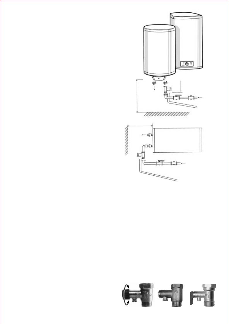
As shown in the drawing the input and output pipes must be on the left side when the heater is installed horizontally.
Should the unit be close to a wall leave the recommended minimum-space for maintenance and service.
Do not install the heater with its wall mounts against the floor nor on a horizontal plane.
HYDRAULIC INSTALLATION
The heater must be connected to the water supply mains.
a)The safety valve - supplied with the heaterMUST be installed on the cold water input (see right side)
-Before connecting the safety valve with the heater, the connecting pipe must be rinsed carefully.
-The draining pipe and the safety valve must be left open to the air and be installed in a continuous downward slope.
Water expands when heated. The units of the series classic, basis and comfort are supplied with a safety valve that lets the expanding water flow back into the cold-water feed.
The units of the series classic/N and comfort/N have a safety valve that prevents the expanding water (N=non return) from flowing back into the cold-water feed. Here a suitable siphon for the absorption of the expanding water is to install.
The drain of the safety valve must not be blocked.
To open the safety valve (not safety valve basis) to let the water flow from the heater - via the outlet - turn the knob clockwise or counterclockwise as you please.
The proper operating of the safety valve should be tested periodically that way:
-turn the knob clockwise or counterclockwise up to the top position
-the water should flow out of the passage
-turn the knob to its down position
The pressure rating is indicated on the knob.
b)If the water-supply pressure exceeds 5 bar, a type-approved reducing valve must be installed.
Hot water |
6 |
|
mm air inlet |
|
Min.20 |
||
|
Safety |
2 |
|
cm |
valve 1 |
|
|
|
|
Cold water |
|
50 |
|
3 |
|
|
|
||
|
|
4 |
5 |
50 cm
|
|
Hot water |
6 |
|
|
|
|
|
|
|
|
|
6 |
|
air inlet |
2 |
1 |
|
|
20 mm |
Safety valve |
|
||
|
|
|
Cold water |
|
Min. |
|
|
|
|
|
3 |
4 |
5 |
1.Safety valve
2.Turning knob for cleaning and draining
3.Draining pipe for the safety valve
4.Stop valve
5.Reducing valve - necessary when pressure is more than 5 barto be installed after the “meter”
6.Earthed plastic sleeves (supplied with the heater)
ELECTRIC INSTALLATION
All storage water heaters of the EWH-series are of 220/230 V single phase design. Before connecting make sure that the mains supply and unit input features coincide.
The heaters installation procedure is totally straightforward and only requires that Low Voltage Electronic Regulations are met. Although well known by the installers we would like to point out some of the basics:
“The following volumes and provisions shall be taken into account for installations in bathrooms or toilets”.
PROHIBITED VOLUME.- It is the volume limited by the tangential and vertical planes with respect to the outer edges of bathtub, toilet pan or shower enclosure and by a plane situated 2,25 m above the same or the floor, should the units be embedded in the same.
Safety valve |
Safety valve basis |
Safety valve |
 Loading...