


Section 61223424L2-5A
Issue 1, December 2003
CLEI Code: T1L497PC_ _
HDSL4 T200 H4TU-R
Installation and Maintenance Practice
CONTENTS |
|
||
1. |
General...................................................................................... |
1 |
|
2. |
Installation ................................................................................ |
2 |
|
3. |
Connections .............................................................................. |
5 |
|
4. |
HDSL4 System Testing ............................................................ |
5 |
|
5. |
Front Panel Operation............................................................... |
7 |
|
6. |
Control Port Operation.............................................................. |
7 |
|
7. |
HDSL4 Deployment Guidelines............................................. |
18 |
|
8. |
Maintenance............................................................................ |
23 |
|
9. |
Specifications.......................................................................... |
23 |
|
10. |
Warranty and Customer Service ............................................. |
23 |
|
Appendix A. HDSL4 Loopbacks.............................................. |
A-1 |
||
TABLES |
|
||
Table 1. |
ADTRAN Unit Compatability........................................ |
1 |
|
Table 2. |
H2TU-R Enclosure Compatibility .................................. |
2 |
|
Table 3. |
Compliance Codes .......................................................... |
2 |
|
Table 4. |
Front Panel Indicators..................................................... |
3 |
|
Table 5. |
Provisioning Options ...................................................... |
4 |
|
Table 6. |
Attenuation limits ......................................................... |
18 |
|
Table 7. |
Range Limits: 26 Gauge / 70°F / PIC.......................... |
18 |
|
Table 8. |
Range Limits: 24 Gauge / 70°F / PIC.......................... |
18 |
|
Table 9. |
Single Pair DC Resistance Value.................................. |
19 |
|
Table 10. HDSL4 Insertion Loss Values ...................................... |
22 |
||
Table 11. Single Span and First Segment of Repeatered Loop .... |
22 |
||
Table 12. Second or Third Segment of Repeatered Loop............. |
22 |
||
Table 13. |
Troubleshooting Guide ................................................. |
23 |
|
Table 14. HDSL4 T200 H4TU-R Specifications.......................... |
24 |
||
Table A-1. HDSL4 Loopback Control Codes............................ |
A-2 |
||
Table A-2. Loopback Control Codes ......................................... |
A-3 |
||
1223424L2 LOCAL
 DSL 1
DSL 1
 DSL 2
DSL 2
 DS1
DS1
 ALM
ALM
ESF/ SF
(YEL) (GRN)
B8ZS/AMI
(YEL) (GRN)
LLB/ RLB
(YEL) (GRN)
LOC
LBK
REM
TX
TX
M
O
N
RX RX
R S 2 3 2
1. GENERAL
The ADTRAN 4-wire T200 HDSL4 transceiver unit for the remote end (H4TU-R), P/N 1223424L2, is a network terminating unit used to deploy an HDSL4 T1 circuit using 4-wire metallic facilities. See Figure 1.
This version of the H4TU-R works with multiple list versions of the HDSL4 transceiver unit for the central office (H4TU-C) and repeater (H4R) as listed in
Table 1.
Revision History
This is the initial release of this document. Future revisions to this document will be explained in this subsection.
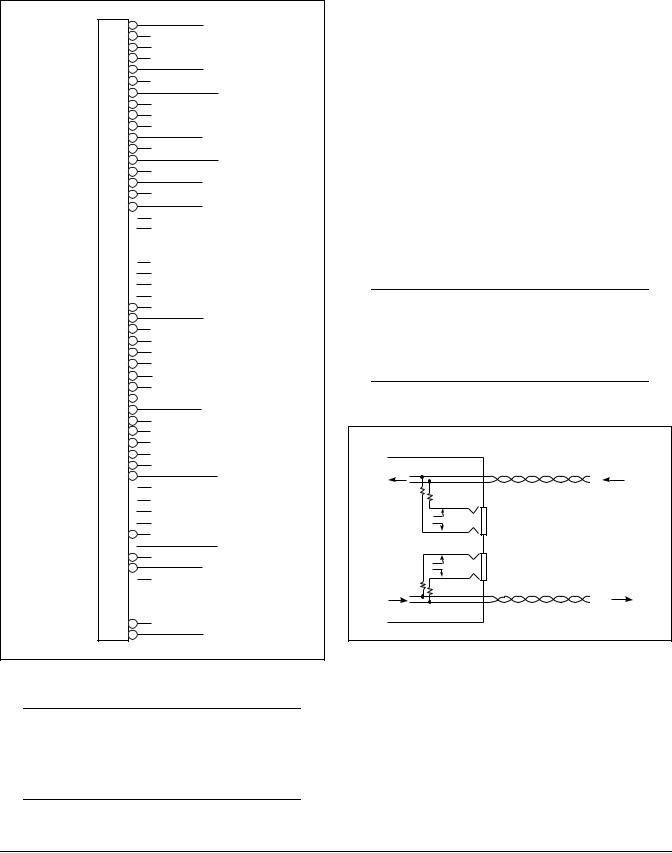
Figure 1. ADTRAN HDSL4 T200 H4TU-R
Table 1. ADTRAN Unit Compatability
Unit Number |
Description |
|
|
122x401L1 or L2 |
220 H4TU-C |
|
|
122x403L1 or L2 |
DDM+ H4TU-C |
|
|
122x404L1 or L2 |
3192 H4TU-R |
|
|
118141xL1 |
Total Access H4TU-C |
|
|
122x441L1 |
T200 H4R |
|
|
122x445L1 |
239 H4R |
|
|
NOTE: x = any generic release number
61223424L2-5A |
Trademarks: Any brand names and product names included in this document are |
1 |
trademarks, registered trademarks, or trade names of their respective holders. |

Description
The T200 H4TU-R can be deployed in circuits using one H4TU-C, one H4TU-R, and up to two H4Rs.
The T200 H4TU-R terminates local loop HDSL4 signals originating from the Central Office (CO) unit and transforms the HDSL4 signal into traditional DS1 signals to be delivered to the customer.
The T200 H4TU-R can be used with any H4TU-C to complete an HDSL4 circuit with up to two H4Rs. Local power is provided through the enclosure.
NOTE
This unit is intended for Local Power Only. If a span powered unit is needed, refer to P/N 122x426L2.
The H4TU-R is a T200 mechanics card which will fit Type 200 or Type 400 mechanics enclosures, as listed in Table 2. This table also provides reference information on the ADTRAN enclosures.
Table 2. H4TU-R Enclosure Compatibility
Part |
Description1 |
Document |
Number |
|
Number |
|
|
|
1242007Lx |
HR12 Metal |
61242007LX-5x |
|
Enclosure Remote |
|
|
Shelf |
|
|
|
|
1242008L1 |
HR4 Installation/ |
61242008L1-5 |
|
Maintenance |
|
|
|
|
1242034L2 |
T400 Single Mount |
61242034L2-5 |
|
(removable RJ-48 |
|
|
jacks) |
|
|
|
|
1242034L3 |
T400 Single-Mount |
61242034L3-5 |
|
High Voltage |
|
|
Enclosure |
|
|
|
|
1245034L12 |
T200 Dual-Mount |
61245034L1-5 |
|
Installation/ |
|
|
Maintenance |
|
|
|
|
1In all applications the H4TU-R must be installed in NEBS compliant and UL listed enclosures to insure full compliance with this unit.
2ADTRAN’s T200 Dual-Mount housing (P/N 1245034L1) is required when using the T200 H4TU-R for HDSL Loop Support System (H-LSSTM) protection circuits.
Compliance
Table 3 shows the compliance codes for the T200 H4TU-R. This product is intended for installation in equipment with a Type “B” or “E” enclosure.
This product meets all requirements of Bellcore GR- 1089-CORE (Class A2), ANSI T1.418-2002 and is NRTL listed to the applicable UL standards.
Table 3. Compliance Codes
Code |
Input |
Output |
|
|
|
Power Code (PC) |
C |
C |
|
|
|
Telecommunication Code (TC) |
X |
X |
|
|
|
Installation Code (IC) |
A |
– |
|
|
|
2. INSTALLATION
After unpacking the unit, inspect it for damage. If damage is discovered, file a claim with the carrier, then contact ADTRAN. Refer to the Warranty and Customer Service section in this practice. The settings on the H4TU-C are encoded and transmitted to the T200 H4TU-R once the circuit has achieved synchronization. There are no switch settings on the T200 H4TU-R.
To install the T200 H4TU-R, perform the following steps:
1.If present, remove the Access Module Blank from the appropriate access module slot of the enclosure.
2.Hold the T200 H4TU-R by the front panel while supporting the bottom edge of the module.
3.Align the module edges to fit in the lower and upper guide grooves for the module slot.
4.Slide the module into the slot. Simultaneous thumb pressure at the top and at the bottom of the module will ensure that the module is firmly seated against the backplane of the enclosure.
WARNING
Up to –200 VDC may be present on telecommunications wiring. Ensure chassis ground is properly connected.
2 |
Issue 1, December 2003 |
61223424L2-5A |

Front Panel LED Indicators
There are seven front panel mounted status LED indicators. Each indicator is described in Table 4.
Table 4. Front Panel LED Indicators
Front Panel |
Name |
Indication |
Description |
|
|
|
DSL 1 |
Green |
DSL Loop 1 sync, no errors currently detected, and signal margin ≥3dB |
1223424L2 |
|
Red |
No DSL Loop 1 sync, errors being detected, or signal margin <3dB |
|
LOCAL |
|
|||
DSL 1 |
DSL 2 |
Green |
DSL Loop 2 sync, no errors currently detected, and signal margin ≥3dB |
|
DSL 2 |
||||
DS1 |
|
|
Red |
No DSL Loop 2 sync, errors being detected, or signal margin <3dB |
ALM |
|
|
||
|
DS1 |
Green |
DS1 signal is present and no errors currently being detected |
|
(YEL) (GRN) |
||||
ESF/ SF |
|
|
|
|
B8ZS/AMI |
|
Red |
No DS1 signal or signal is present with errors |
|
LLB/ RLB |
|
|||
(YEL) |
(GRN) |
|
|
|
(YEL) |
(GRN) |
|
|
|
|
|
ALM |
OFF |
No active alarm present |
LOC |
|
|
Red |
Loss of DS1 signal to the unit |
|
|
|
|
|
REM |
LBK |
|
Yellow |
Loss of DSX-1 signal to the H4TU-C |
|
|
|
|
|
|
|
ESF/SF |
OFF |
Unit is provisioned for UNFRAMED data |
TX |
TX |
|
Yellow |
Unit is provisioned for ESF data |
|
|
|||
M |
|
|
||
O |
|
|
|
|
N |
|
|
|
|
RX |
RX |
|
Green |
Unit is provisioned for SF data |
|
|
|
|
|
R |
|
B8ZS/AMI |
Yellow |
Unit is provisioned for B8ZS coded data |
|
|
|
|
|
S |
|
|
Green |
Unit is provisioned for AMI data |
3 |
|
|
||
2 |
|
|
|
|
2 |
|
|
|
|
|
|
LLB/RLB |
OFF |
Unit is NOT in loopback |
|
|
|
Yellow |
Unit is in loopback (network and/or customer) |
|
|
|
Green |
H4TU-C is in loopback toward this unit |
61223424L2-5A |
Issue 1, December 2003 |
3 |

Remote Provisioning
There are no configuration switches for the T200 H4TU-R. Configuration is performed via software discussed in the Control Port Operation section of this practice.
The provisioning settings can be viewed and manipulated through management access via the front panel RS-232 port. Table 5 lists the available provisioning options and their factory default settings.
Table 5. Provisioning Options
Provisioning Option |
Option Settings |
Default Settings |
|
|
|
|
|
1. |
DSX-1 Line Build Out |
0-133 ft., 133-266 ft., 266-399 ft., |
0 to 133 ft. |
|
|
399-533 ft., 533-655 ft. |
|
|
|
|
|
2. DSX-1/DS1 Line Code |
B8ZS, AMI |
B8ZS |
|
|
|
|
|
3. |
DSX-1/DS1 Framing |
SF, ESF, Unframed, Auto |
ESF |
|
|
|
|
4. |
Force Frame Conversion 1 |
Disabled, Enabled |
Disabled |
5. |
Smartjack Loopback |
Disabled, Enabled |
Enabled |
|
|
|
|
6. |
Loopback Time Out |
None, 120 Min |
120 Minutes |
|
|
|
|
7. |
Latching Loopback Mode 2 |
T1 (Disabled), FT1 (Enabled) |
T1 (Disabled) |
8. |
DS1 Tx Level |
0 dB, -7.5 dB, -15 dB |
0 dB |
|
|
|
|
9. |
Customer Loss Indicator 3 |
AIS, Loopback, AIS/CI |
AIS/CI |
11. Performance Reporting Messages |
None, SPRM, NPRM, AUTO (both) |
AUTO |
|
|
|
|
|
12. Loop Attenuation Alarm Threshold |
0 (Disabled), 1-99 dB |
34 dB |
|
|
|
|
|
13. SNR Margin Alarm Threshold |
0 (Disabled), 1-15 dB |
04 dB |
|
|
|
|
|
14. Remote Provisioning |
Disabled, Enabled |
Enabled |
|
|
|
|
|
1The forced frame format conversion (FFFC) mode sets the H2TU-C to ESF and the H2TU-R to SF. This mode should be used to force SF (DS1 from customer) to ESF (DSX-1 to network) conversion in the absence of network-provided ESF framing.
2Latching Loopback Mode
•T1 — When optioned for T1 mode, the unit does not respond to DDS Latching Loopback codes.
•FT1 — DDS Latching Loopback operation is supported. The H4TU-C and any H4R units which are in the HDSL circuit are treated as identical Tandem Data ports and the HTU-R is treated as a different Tandem Data port.
NOTE: When operating in FT1 mode and during periods of T1 loss of signal, LOS, or T1 AIS from the customer CI, the HDSL system will send in the network direction from the HTU-C a Fractional DS1 idle signal consisting of a repeating 7E (HEX) byte payload within a framed/unframed T1 signal. In addition, when optioned for FT1 mode, the setting for Customer Loss Response is ignored.
3Customer Loss Indicator
•AIS — Send AIS to network upon T1 loss of signal or T1 AIS from customer.
•LPBK — HTU-R initiates a network loopback upon T1 loss of signal or T1 AIS from customer.
•AIS/CI — HTU-R sends customer disconnect indication upon loss of signal, loss of synchronization, or receipt of T1 AIS from customer.
NOTE: The CI is generated by transmitting the framing received from the network while overwriting the payload with a repeating pattern. For applications where the DS1 is Extended Superframe, the data link is overwritten with a Yellow Alarm that is interrupted once every second by a 100 milli-second code burst of 7E (HEX).
4 |
Issue 1, December 2003 |
61223424L2-5A |
3. CONNECTIONS
All connections of the T200 H4TU-R are made through card edge connectors. Figure 2 gives the card edge pin assignments for the T200 H4TU-R circuit pack.
1 |
Chassis Ground |
|
|
||
2 |
|
|
3 |
|
|
4 |
DS1 TX Tip |
|
5 |
||
|
||
6 |
HDSL4 Tip Loop 1 |
|
7 |
||
|
||
8 |
|
|
9 |
|
|
10 |
Chassis Ground |
|
11 |
||
|
||
12 |
HDSL4 Ring Loop 1 |
|
13 |
||
|
||
14 |
DS1 TX Ring |
|
15 |
||
|
||
16 |
–24 V/-48 V Return |
|
17 |
||
|
18
19
20
21
22
23
24
25
26 |
Chassis Ground |
|
27 |
||
|
||
28 |
|
|
29 |
|
|
30 |
|
|
31 |
|
|
32 |
|
|
33 |
|
|
34 |
–24 VDC/-48 VDC |
|
35 |
||
|
||
36 |
|
|
37 |
|
|
38 |
|
|
39 |
|
|
40 |
HDSL4 Tip Loop 2 |
|
41 |
||
|
42
43
44
45
46
47  HDSL4 Ring Loop 2
48
DS1 RX Ring
49
50
51
52
53
54
DS1 RX Tip
55
Figure 2. H4TU-R Edge Connector Wiring
CAUTION
Ensure chassis ground is properly connected for either standalone or shelf-mounted applications.
4. HDSL4 SYSTEM TESTING
The T200 H4TU-R provides diagnostic, loopback, and signal monitoring capabilities.
The seven front panel LEDs provide diagnostics for HDSL4 loops, DS1 signals, alarms, provisioning, and loopbacks. Refer to the Installation section for details.
The H4TU-R provides a bidirectional loopback via the loopback button on the front panel. Refer to the
H4TU-R Network Loopbacks and Customer Loopbacks sections for more details.
DS1 MON Bantam Jacks
The MON jack provides a non intrusive access point for monitoring the characteristics of the transmit and receive signals at the DS1 interface point.
For example, the DS1 MON jack on the H4TU-R could be used to connect to a bit error rate tester to monitor for synchronization, test patterns, etc.
Figure 3 is an illustration of specific jack detail.
NOTE
For the MON jacks, the TX and RX indications relate to the direction of the signal to/from the CPE.
H4TU-R
T
R
TX
DS1
CPE
MON
DS1
INTERFACE
RX
T1
R1
Figure 3. H4TU-R MON Diagram
61223424L2-5A |
Issue 1, December 2003 |
5 |
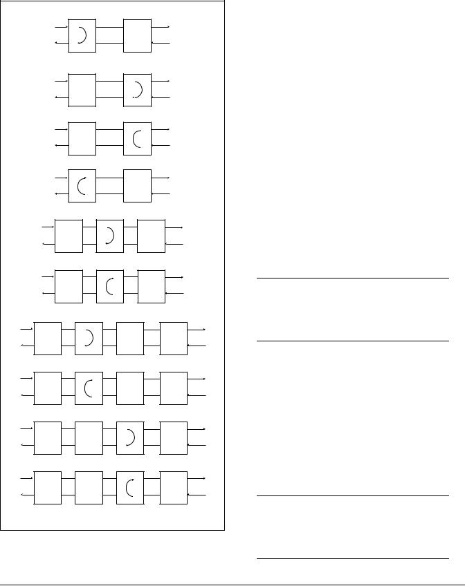
H4TU-R Network Loopbacks
The loopback position is a logic loopback located within the H4TU-R internal HDSL4 transceiver. See
Figure 4.
|
|
|
H4TU-C Network-Side Loopback |
|
||
|
|
|
|
|
AIS |
|
|
|
DSX-1 |
|
LOCAL |
DS1 |
|
|
|
|
LOOP |
|
||
|
|
|
|
X |
|
|
|
|
|
|
|
|
|
|
|
|
H4TU-C |
H4TU-R |
|
|
|
|
|
H4TU-R Network-Side Loopback and/or |
|
||
|
|
|
H4TU-R NIU Loopback |
|
|
|
|
|
|
|
|
AIS |
|
|
|
DSX-1 |
|
LOCAL |
DS1 |
|
|
|
|
LOOP |
|
||
|
|
|
|
X |
|
|
|
|
|
|
|
|
|
|
|
|
H4TU-C |
H4TU-R |
|
|
|
|
|
H4TU-R Customer-Side Loopback |
|
||
|
|
|
X |
|
|
|
|
|
DSX-1 |
|
LOCAL |
DS1 |
|
|
|
|
LOOP |
|
||
|
|
|
|
|
|
|
|
|
AIS |
H4TU-C |
H4TU-R |
|
|
|
|
|
|
|||
|
|
|
H4TU-C Customer-Side Loopback |
|
||
|
|
|
X |
|
|
|
|
|
DSX-1 |
|
LOCAL |
DS1 |
|
|
|
|
LOOP |
|
||
|
|
|
|
|
|
|
|
|
AIS |
H4TU-C |
H4TU-R |
|
|
|
|
H4R Network-Side Loopback |
|
|
||
|
|
|
|
|
|
AIS |
|
DSX-1 |
|
|
|
|
DS1 |
|
|
|
|
|
X |
|
|
|
H4TU-C |
H4R |
H4TU-R |
|
|
|
|
H4R Customer-Side Loopback |
|
|
||
|
|
X |
|
|
|
|
|
DSX-1 |
|
|
|
|
DS1 |
|
|
|
|
|
|
|
|
AIS |
H4TU-C |
H4R |
H4TU-R |
|
|
|
H4R1 Network-Side Loopback |
|
AIS |
|||
|
|
|
|
|
|
|
DSX-1 |
|
|
|
|
|
DS1 |
|
|
|
|
|
|
X |
|
H4TU-C |
|
H4R1 |
H4R2 |
H4TU-R |
|
|
H4R1 Customer-Side Loopback |
|
|
|||
|
X |
|
|
|
|
|
DSX-1 |
|
|
|
|
|
DS1 |
AIS |
H4TU-C |
|
H4R1 |
H4R2 |
H4TU-R |
|
|
H4R2 Network-Side Loopback |
|
AIS |
|||
|
|
|
|
|
|
|
DSX-1 |
|
|
|
|
|
DS1 |
|
|
|
|
|
|
X |
|
H4TU-C |
|
H4R1 |
H4R2 |
H4TU-R |
|
|
H4R2 Customer-Side Loopback |
|
|
|||
|
X |
|
|
|
|
|
DSX-1 |
|
|
|
|
|
DS1 |
AIS |
H4TU-C |
|
H4R1 |
H4R2 |
H4TU-R |
|
|
|
|
|
X = Signal Inactive |
|
|
Figure 4. HDSL4 Loopbacks
The H4TU-R responds to multiple loopback activation processes:
•First, manual loopback on the H4TU-R and/or the H4TU-C unit may be controlled from the front panel. Refer to the Front Panel Operation section of this practice for more detail.
•Second, loopback activation may be accomplished using the control port of the H4TU-R.
•Third, the H4TU-R will respond to the industry standard HDSL loopback codes as designated in the ANSI document T1E1.4/92. These are described in
Appendix A, HDSL4 Loopbacks.
•Fourth, the H4TU-R responds to T1 Network Interface Unit (NIU) loopback codes as described in Bellcore TR-TSY-000312, as follows:
In-Band Codes |
|
Loop up |
11000 (2 in 5) |
Loop down |
11100 (3 in 5) |
ESF Codes |
|
Loop up |
1111 1111 0100 1000 (FF 48) |
Loop down |
1111 1111 0010 0100 (FF 24) |
Receiving the in-band codes for more than five seconds or the ESF codes four consecutive times will cause the appropriate loopback action. The ESF codes must be transmitted in the Facility Data Link (FDL).
NOTE
The NIU loopback option must be enabled before the H4TU-R can respond to the NIU loopback.
The H4TU-R will respond to the loopback codes by activating the NIU loopback from either the disarmed or armed state. The loop down codes will return the H4TU-R to the disarmed or de-activated state depending upon the code utilized.
Customer Loopbacks
In addition to the loopbacks in the direction of the network, the H4TU-R may also be looped back in the direction of the customer. The H4TU-C and H4TU-R Customer Side Loopbacks are illustrated in Figure 4.
NOTE
Network and customer loopbacks are governed by the loopback time out option (Default=120 minutes).
6 |
Issue 1, December 2003 |
61223424L2-5A |

5. FRONT PANEL OPERATION
The front panel contains two pushbuttons. These are labeled LOC and REM.
The LOC pushbutton controls a bidirectional loopback at the H4TU-R. Pressing the button causes a bidirectional loopback to occur. If the bidirectional loopback is active, pressing the button a second time will disable the loopback.
The REM pushbutton controls a bidirectional loopback at the H4TU-C. Pressing the button causes a loopback toward the H4TU-R and network to occur. If the loopback is active, pressing the button a second time will disable the loopback.
6. CONTROL PORT OPERATION
The H4TU-R provides a front panel-mounted DB-9 connector that supplies an RS-232 interface for connection to a controlling terminal. The pinout of the DB-9 is illustrated in Figure 5.
1
6
2 TXD (Transmit Data)
7
3 RXD (Receive Data)
8
4
9
5 SGN (Signal Ground)
Figure 5. RS-232 (DB-9) Connector Pinout
The terminal interface operates at data rates from 1.2, 2.4, 4.8, 9.6, and 19.2 kbps. The asynchronous data format is fixed at 8 data bits, no parity, and 1 stop bit.
NOTE
If a personal computer with terminal emulation capability is being used, be sure to disable any power-saving programs. Otherwise, communication between the PC and the HDSL4 unit may be disrupted, resulting in misplaced characters or screen time outs.
Operation
The screens illustrated in the following section apply to an HDSL4 circuit deployed with the ADTRAN HDSL4 technology. The circuit includes an H4TU-C, up to two H4Rs and an H4TU-R. Other configurations are possible (such as use of another vendor's equipment) and their displays will vary slightly from those shown in this section.
A terminal session is initiated by entering multiple spacebar characters which are used by the H4TU-R to determine the speed of the terminal. Once the speed has been determined, an HDSL4 Main Menu is presented as illustrated in Figure 6.
61223424L2-5A |
Issue 1, December 2003 |
7 |

This ADTRAN HDSL4 Main Menu provides access to detailed performance and configuration information. The OAM&P (Operation, Administration, Maintenance, and Provisioning) screens are available as listed on the Main Menu (Figure 6). To access a particular menu item, press the number associated with that item, and press ENTER.
The HDSL4 Unit Information Screen (Figure 7) provides detailed product information on each component in the HDSL4 circuit. This screen also displays contact information for ADTRAN Technical Support, Internet site, and address.
Circuit ID: |
10/01/03 09:29:45 |
|
Adtran HDSL4 Main Menu |
1. |
HDSL4 Unit Information |
2. |
Provisioning |
3. |
Span Status |
4. |
Loopbacks and Test |
5. |
Performance History |
6. |
Scratch Pad, Ckt ID, Time/Date |
7. |
Terminal Modes |
8. |
Alarm History |
9. |
Event History |
10. |
System PM/Screen Report |
11. |
Clear PM and Alarm Histories |
12. |
Troubleshooting |
13. |
Virtual Terminal Control |
Selection:
Figure 6. HDSL4 Main Menu
Circuit ID: |
return to previous |
10/01/03 09:29:45 |
Press ESC to |
menu |
|
|
ADTRAN |
|
901 Explorer Boulevard |
|
|
Huntsville, Alabama 35806-2807 |
||
--------------------- For Information or Technical Support --------------------- |
||
Support Hours ( Normal 7am - |
7pm CST, Emergency |
7 days x 24 hours ) |
Phone: 800.726.8663 / 888.873.HDSL |
Fax: 256.963.6217 |
Internet: www.adtran.com |
--------------------------------------------------------------------------------
ADTN |
H4TU-C |
ADTN |
H4TU-R |
P/N: |
1223403L2 |
P/N: |
1223424L2 |
S/N: |
123456789 |
S/N: |
123456789 |
CLEI: |
T1L7PODAAA |
CLEI: |
T1L497PCAA |
Manf: |
01/01/2000 |
Manf: |
01/01/2000 |
Ver: |
A00 |
Ver: |
A01 |
ADTN |
H4R1 |
ADTN |
H4R2 |
P/N: |
1221445L1 |
P/N: |
1221445L1 |
S/N: |
BB50A8343 |
S/N: |
BB50A8353 |
CLEI: |
T1R5YP3DAA |
CLEI: |
T1R5YP3DAA |
Manf: |
02/12/2002 |
Manf: |
02/12/2002 |
Ver: |
A01 |
Ver: |
A01 |
Figure 7. Unit Information Screen
8 |
Issue 1, December 2003 |
61223424L2-5A |
 Loading...