


 Loading...
®
MX2800 M13 Multiplexer
User Manual
Manual Part Number - 61200290L1-1G
4205290L1 AC Non-Redundant Version with Modem
4205290L2 AC Redundant Version with Modem
4205290L3 DC Non-Redundant Version with Modem
4205290L4 DC Redundant Version with Modem
4205290L5 AC Non-Redundant Version
4205290L6 AC Redundant Version
4205290L7 DC Non-Redundant Version
4205290L8 DC Redundant Version
1205288L1 Controller Card
1205288L2 Controller Card
1200291L1 Breakout Panel
4175043L2 Battery Backup
1200657L2 Battery Backup Adapter Cable
1200287L1 Amp to Punch-Down Cable 25 ft.
1200287L5 Amp to Punch-Down Cable 50 ft.
1200287L7 Amp to Punch-Down Cable 100 ft.
1200291L5 BNC patch panel
1200466L1 Fan Faceplate
61200290L1-1G October 2004

MX2800 M13 Multiplexer System Manual
Trademarks
Any brand names and product names included in this manual are trademarks, registered trademarks, or trade names of their respective holders.
OpenView™ is a trademark of Hewlett-Packard Company.
Spectrum® is a registered trademark of Cabletron.
ADVISION™ is a trademark of ADTRAN.
Total Access Element Management System™ is a trademark of ADTRAN.
To the Holder of the Manual
The contents of this manual are current as of the date of publication. ADTRAN® reserves the right to change the contents without prior notice.
In no event will ADTRAN be liable for any special, incidental, or consequential damages or for commercial losses even if ADTRAN has been advised thereof as a result of issue of this publication.
®
901 Explorer Boulevard
P.O. Box 140000
Huntsville, AL 35814-4000
(256) 963-8000
©2004 ADTRAN, Inc.
All Rights Reserved.
Printed in U.S.A.
ii |
61200290L1-1G |

MX2800 M13 Multiplexer System Manual
Revision History
Document |
Date |
Description of Changes |
|
Revision |
|||
|
|
||
|
|
|
|
G |
Oct. 2004 |
This revision of the MX2800 M13 Multiplexer User Manual has been updated to |
|
|
|
include new features for the System Control Unit (P/N 1185002L2). |
|
|
|
|
Conventions
The following typographical conventions are used in this document:
This font indicates a cross-reference link. First-time references to tables and figures are shown in this font.
This font indicates screen menus, fields, and parameters.
THIS FONT indicates keyboard keys (ENTER, ESC, ALT). Keys that are to be pressed simultaneously are shown with a plus sign (ALT+X indicates that the ALT key and X key should be pressed at the same time).
This font indicates references to other documentation, sections of documents, and is also used for emphasis.
This font indicates on-screen messages and prompts. This font indicates text to be typed exactly as shown.
This font indicates silkscreen labels or other system label items. This font is used for strong emphasis
NOTE
Notes inform the user of additional but essential information or features.
CAUTION
Cautions inform the user of potential damage, malfunction, or disruption to equipment, software, or environment.
WARNING
Warnings inform the user of potential bodily pain, injury, or death.
61200290L1-1G |
iii |

MX2800 M13 Multiplexer System Manual
FCC Radio Frequency Interference Statement
This equipment has been tested and found to comply with the limits for a Class A digital device, pursuant to Part 15 of the FCC Rules. These limits are designed to provide reasonable protection against harmful interference when the equipment is operated in a commercial environment. This equipment generates, uses, and can radiate radio frequency energy and, if not installed and used in accordance with the instruction manual, may cause harmful interference to radio frequencies. Operation of this equipment in a residential area is likely to cause harmful interference in which case the user will be required to correct the interference at his own expense.
NOTE
Shielded cables must be used with this unit to ensure compliance with
Class A FCC limits.
CAUTION
Changes or modifications to this unit not expressly approved by the party responsible for compliance could void the user’s authority to operate the equipment.
Canadian Emissions Requirements
This digital apparatus does not exceed the Class A limits for radio noise emissions from digital apparatus as set out in the interference-causing equipment standard entitled “Digital Apparatus,” ICES-003 of the Department of Communications.
Cet appareil nuerique respecte les limites de bruits radioelectriques applicables aux appareils numeriques de Class A prescrites dans la norme sur le materiel brouilleur: “Appareils Numeriques,” NMB-003 edictee par le ministre des Communications.
Canadian Equipment Limitations
Notice: The Canadian Industry and Science Canada label identifies certified equipment. This certification means that the equipment meets certain telecommunications network protective, operational, and safety requirements. The Department does not guarantee the equipment will operate to the user’s satisfaction.
Before installing this equipment, users should ensure that it is permissible to be connected to the facilities of the local telecommunications company. The equipment must also be installed using an acceptable method of connection. In some cases, the company’s inside wiring associated with a single line individual service may be extended by means of a certified connector assembly (telephone extension cord). The customer should be aware that compliance with the above limitations may not prevent degradation of service in some situations.
iv |
61200290L1-1G |

MX2800 M13 Multiplexer System Manual
Repairs to certified equipment should be made by an authorized Canadian maintenance facility designated by the supplier. Any repairs or alterations made by the user to this equipment, or equipment malfunctions, may give the telecommunications company cause to request the user to disconnect the equipment.
Users should ensure for their own protection that the electrical ground connections of the power utility, telephone lines and internal metallic water pipe system, if present, are connected together. This precaution may be particularly important in rural areas.
CAUTION
Users should not attempt to make such connections themselves, but should contract the appropriate electric inspection authority or an electrician, as appropriate.
The Load Number (LN) assigned to each terminal device denotes the percentage of the total load to be connected to a telephone loop which is used by the device, to prevent overloading. The termination on a loop may consist of any combination of devices subject only to the requirement that the total of the Load Numbers of all devices does not exceed 100.
Training
ADTRAN offers product training. The training courses include overviews on product features and functions while covering applications of ADTRAN’s product lines. ADTRAN provides a variety of training options, including customized training and course taught at our facilities or at customer sites. For more information about training, please contact us.
Training Phone: |
800-615-1176, ext. 7500 |
Training Fax: |
256-963-6700 |
Training Email: |
training@adtran.com |
61200290L1-1G |
v |

MX2800 M13 Multiplexer System Manual
This page is intentionally blank.
vi |
61200290L1-1G |

MX2800 M13 Multiplexer User Manual
Contents
Section 1 |
|
Product Overview . . . . . . . . . . . . . . . . . . . . . . . . . . . . . . . . . . . . . . . . . . . . . . . . . . . . . . . . . |
1-1 |
1. Introduction . . . . . . . . . . . . . . . . . . . . . . . . . . . . . . . . . . . . . . . . . . . . . . . . . . . . . . . . . . . . . . . . . . . 1-1
2. Controller Card 1:1 Redundancy . . . . . . . . . . . . . . . . . . . . . . . . . . . . . . . . . . . . . . . . . . . . . . . . . . 1-2
3. T3 Overview. . . . . . . . . . . . . . . . . . . . . . . . . . . . . . . . . . . . . . . . . . . . . . . . . . . . . . . . . . . . . . . . . . . 1-2
4. SNMP . . . . . . . . . . . . . . . . . . . . . . . . . . . . . . . . . . . . . . . . . . . . . . . . . . . . . . . . . . . . . . . . . . . . . . . . 1-2
Network Manager . . . . . . . . . . . . . . . . . . . . . . . . . . . . . . . . . . . . . . . . . . . . . . . . . . . . . . . . . . . 1-2
Agent . . . . . . . . . . . . . . . . . . . . . . . . . . . . . . . . . . . . . . . . . . . . . . . . . . . . . . . . . . . . . . . . . . . . . 1-3
MIB . . . . . . . . . . . . . . . . . . . . . . . . . . . . . . . . . . . . . . . . . . . . . . . . . . . . . . . . . . . . . . . . . . . . . . 1-3
5. Telnet . . . . . . . . . . . . . . . . . . . . . . . . . . . . . . . . . . . . . . . . . . . . . . . . . . . . . . . . . . . . . . . . . . . . . . . . 1-3
6. TL1 . . . . . . . . . . . . . . . . . . . . . . . . . . . . . . . . . . . . . . . . . . . . . . . . . . . . . . . . . . . . . . . . . . . . . . . . . . 1-3
7. Available Options . . . . . . . . . . . . . . . . . . . . . . . . . . . . . . . . . . . . . . . . . . . . . . . . . . . . . . . . . . . . . . 1-3
Breakout Panel (P/N 1200291L1) . . . . . . . . . . . . . . . . . . . . . . . . . . . . . . . . . . . . . . . . . . . . . . . 1-3 E1 Patch Panel (P/N 1200291L5) . . . . . . . . . . . . . . . . . . . . . . . . . . . . . . . . . . . . . . . . . . . . . . . 1-3 Battery Backup (P/N 4175043L2) . . . . . . . . . . . . . . . . . . . . . . . . . . . . . . . . . . . . . . . . . . . . . . . 1-4 Fan Faceplate (P/N 1200466L1) . . . . . . . . . . . . . . . . . . . . . . . . . . . . . . . . . . . . . . . . . . . . . . . . 1-4
Section 2
Installation and Operation. . . . . . . . . . . . . . . . . . . . . . . . . . . . . . . . . . . . . . . . . . . . . . . . . . . 2-1
1. Introduction . . . . . . . . . . . . . . . . . . . . . . . . . . . . . . . . . . . . . . . . . . . . . . . . . . . . . . . . . . . . . . . . . . . 2-1
2. Receiving Inspection . . . . . . . . . . . . . . . . . . . . . . . . . . . . . . . . . . . . . . . . . . . . . . . . . . . . . . . . . . . 2-1
3. ADTRAN Shipping Contents . . . . . . . . . . . . . . . . . . . . . . . . . . . . . . . . . . . . . . . . . . . . . . . . . . . . . 2-1
4. Power Up . . . . . . . . . . . . . . . . . . . . . . . . . . . . . . . . . . . . . . . . . . . . . . . . . . . . . . . . . . . . . . . . . . . . . 2-2
5. Rackmount Installation. . . . . . . . . . . . . . . . . . . . . . . . . . . . . . . . . . . . . . . . . . . . . . . . . . . . . . . . . . 2-4
Connecting the Breakout Panel . . . . . . . . . . . . . . . . . . . . . . . . . . . . . . . . . . . . . . . . . . . . . . . . . 2-5
Connecting the E1 Patch Panel . . . . . . . . . . . . . . . . . . . . . . . . . . . . . . . . . . . . . . . . . . . . . . . . . 2-5
6. Rear Panel . . . . . . . . . . . . . . . . . . . . . . . . . . . . . . . . . . . . . . . . . . . . . . . . . . . . . . . . . . . . . . . . . . . . 2-6
LAN Port . . . . . . . . . . . . . . . . . . . . . . . . . . . . . . . . . . . . . . . . . . . . . . . . . . . . . . . . . . . . . . . . . . 2-7
Modem Port . . . . . . . . . . . . . . . . . . . . . . . . . . . . . . . . . . . . . . . . . . . . . . . . . . . . . . . . . . . . . . . . 2-7
Noncritical and Critical Alarm Connectors . . . . . . . . . . . . . . . . . . . . . . . . . . . . . . . . . . . . . . . . . 2-7
DSX-3 Interfaces . . . . . . . . . . . . . . . . . . . . . . . . . . . . . . . . . . . . . . . . . . . . . . . . . . . . . . . . . . . . 2-7
DSX-1/E1 Interfaces . . . . . . . . . . . . . . . . . . . . . . . . . . . . . . . . . . . . . . . . . . . . . . . . . . . . . . . . . 2-8
Power Connection . . . . . . . . . . . . . . . . . . . . . . . . . . . . . . . . . . . . . . . . . . . . . . . . . . . . . . . . . . . 2-8
7. Front Panel . . . . . . . . . . . . . . . . . . . . . . . . . . . . . . . . . . . . . . . . . . . . . . . . . . . . . . . . . . . . . . . . . . . 2-8
61200290L1-1G |
vii |

Contents |
MX2800 M13 Multiplexer User Manual |
|
|
Craft Port . . . . . . . . . . . . . . . . . . . . . . . . . . . . . . . . . . . . . . . . . . . . . . . . . . . . . . . . . . . . . . . . . . 2-8
Establishing Terminal Connection . . . . . . . . . . . . . . . . . . . . . . . . . . . . . . . . . . . . . . . . . . . . 2-9
Main Menu . . . . . . . . . . . . . . . . . . . . . . . . . . . . . . . . . . . . . . . . . . . . . . . . . . . . . . . . . . . . . 2-9
Navigating Within the Menus . . . . . . . . . . . . . . . . . . . . . . . . . . . . . . . . . . . . . . . . . . . . . . 2-10
Status . . . . . . . . . . . . . . . . . . . . . . . . . . . . . . . . . . . . . . . . . . . . . . . . . . . . . . . . . . . . . 2-11
Statistics . . . . . . . . . . . . . . . . . . . . . . . . . . . . . . . . . . . . . . . . . . . . . . . . . . . . . . . . . . . 2-11
Configuration . . . . . . . . . . . . . . . . . . . . . . . . . . . . . . . . . . . . . . . . . . . . . . . . . . . . . . . 2-12
Loopbacks . . . . . . . . . . . . . . . . . . . . . . . . . . . . . . . . . . . . . . . . . . . . . . . . . . . . . . . . . 2-13
Telnet Client . . . . . . . . . . . . . . . . . . . . . . . . . . . . . . . . . . . . . . . . . . . . . . . . . . . . . . . . 2-13
Logout . . . . . . . . . . . . . . . . . . . . . . . . . . . . . . . . . . . . . . . . . . . . . . . . . . . . . . . . . . . . . 2-15
Privilege Level . . . . . . . . . . . . . . . . . . . . . . . . . . . . . . . . . . . . . . . . . . . . . . . . . . . . . . 2-15
ACO Buttons . . . . . . . . . . . . . . . . . . . . . . . . . . . . . . . . . . . . . . . . . . . . . . . . . . . . . . . . . . . . . . 2-15
LED Descriptions . . . . . . . . . . . . . . . . . . . . . . . . . . . . . . . . . . . . . . . . . . . . . . . . . . . . . . . . . . . 2-15
Power Supply A/B Status LEDs . . . . . . . . . . . . . . . . . . . . . . . . . . . . . . . . . . . . . . . . . . . . 2-15
Controller Cards Status LEDs . . . . . . . . . . . . . . . . . . . . . . . . . . . . . . . . . . . . . . . . . . . . . . 2-15
T1/E1 Status LEDs . . . . . . . . . . . . . . . . . . . . . . . . . . . . . . . . . . . . . . . . . . . . . . . . . . . . . . 2-17
8. Replacing or Installing Cards . . . . . . . . . . . . . . . . . . . . . . . . . . . . . . . . . . . . . . . . . . . . . . . . . . . 2-18
Section 3
Configuration . . . . . . . . . . . . . . . . . . . . . . . . . . . . . . . . . . . . . . . . . . . . . . . . . . . . . . . . . . . . . 3-1
1. Introduction . . . . . . . . . . . . . . . . . . . . . . . . . . . . . . . . . . . . . . . . . . . . . . . . . . . . . . . . . . . . . . . . . . . 3-1
2. Network Interface . . . . . . . . . . . . . . . . . . . . . . . . . . . . . . . . . . . . . . . . . . . . . . . . . . . . . . . . . . . . . . 3-4
DS3 Configuration . . . . . . . . . . . . . . . . . . . . . . . . . . . . . . . . . . . . . . . . . . . . . . . . . . . . . . . . . . . 3-4
Framing . . . . . . . . . . . . . . . . . . . . . . . . . . . . . . . . . . . . . . . . . . . . . . . . . . . . . . . . . . . . . . . . 3-4
Line Length . . . . . . . . . . . . . . . . . . . . . . . . . . . . . . . . . . . . . . . . . . . . . . . . . . . . . . . . . . . . . 3-4
Timing . . . . . . . . . . . . . . . . . . . . . . . . . . . . . . . . . . . . . . . . . . . . . . . . . . . . . . . . . . . . . . . . . 3-5
Remote Loopbacks . . . . . . . . . . . . . . . . . . . . . . . . . . . . . . . . . . . . . . . . . . . . . . . . . . . . . . . 3-5
XCV Threshold . . . . . . . . . . . . . . . . . . . . . . . . . . . . . . . . . . . . . . . . . . . . . . . . . . . . . . . . . . 3-6
Protection Configuration . . . . . . . . . . . . . . . . . . . . . . . . . . . . . . . . . . . . . . . . . . . . . . . . . . . . . . 3-6
Active Controller . . . . . . . . . . . . . . . . . . . . . . . . . . . . . . . . . . . . . . . . . . . . . . . . . . . . . . . . . 3-6
Network Protection . . . . . . . . . . . . . . . . . . . . . . . . . . . . . . . . . . . . . . . . . . . . . . . . . . . . . . . 3-6
Maximum Switch Threshold . . . . . . . . . . . . . . . . . . . . . . . . . . . . . . . . . . . . . . . . . . . . . . . . 3-6
Min. Switching Period . . . . . . . . . . . . . . . . . . . . . . . . . . . . . . . . . . . . . . . . . . . . . . . . . . . . . 3-6
Miscellaneous . . . . . . . . . . . . . . . . . . . . . . . . . . . . . . . . . . . . . . . . . . . . . . . . . . . . . . . . . . . . . . 3-7
Loopback Timeout . . . . . . . . . . . . . . . . . . . . . . . . . . . . . . . . . . . . . . . . . . . . . . . . . . . . . . . . 3-7
Shutdown Stand-By . . . . . . . . . . . . . . . . . . . . . . . . . . . . . . . . . . . . . . . . . . . . . . . . . . . . . . 3-7
DS2 Configuration . . . . . . . . . . . . . . . . . . . . . . . . . . . . . . . . . . . . . . . . . . . . . . . . . . . . . . . . . . . 3-7
3. T1/E1 Interface. . . . . . . . . . . . . . . . . . . . . . . . . . . . . . . . . . . . . . . . . . . . . . . . . . . . . . . . . . . . . . . . . 3-8
T1/E1 State . . . . . . . . . . . . . . . . . . . . . . . . . . . . . . . . . . . . . . . . . . . . . . . . . . . . . . . . . . . . . . . . 3-9
Set Multiple . . . . . . . . . . . . . . . . . . . . . . . . . . . . . . . . . . . . . . . . . . . . . . . . . . . . . . . . . . . . . 3-9
T1/E1 Line Coding . . . . . . . . . . . . . . . . . . . . . . . . . . . . . . . . . . . . . . . . . . . . . . . . . . . . . . . . . . 3-10
T1/E1 Line Length . . . . . . . . . . . . . . . . . . . . . . . . . . . . . . . . . . . . . . . . . . . . . . . . . . . . . . . . . . 3-11
T1/E1 Loopback Detection . . . . . . . . . . . . . . . . . . . . . . . . . . . . . . . . . . . . . . . . . . . . . . . . . . . 3-12
T1/E1 Circuit Protection . . . . . . . . . . . . . . . . . . . . . . . . . . . . . . . . . . . . . . . . . . . . . . . . . . . . . . 3-13
T1/E1 Line Identification . . . . . . . . . . . . . . . . . . . . . . . . . . . . . . . . . . . . . . . . . . . . . . . . . . . . . 3-14
XCV Threshold . . . . . . . . . . . . . . . . . . . . . . . . . . . . . . . . . . . . . . . . . . . . . . . . . . . . . . . . . . . . 3-15
4. System Management . . . . . . . . . . . . . . . . . . . . . . . . . . . . . . . . . . . . . . . . . . . . . . . . . . . . . . . . . . 3-16
Management Options . . . . . . . . . . . . . . . . . . . . . . . . . . . . . . . . . . . . . . . . . . . . . . . . . . . . . . . 3-17
viii |
61200290L1-1G |

MX2800 M13 Multiplexer User Manual Contents
Local IP Address . . . . . . . . . . . . . . . . . . . . . . . . . . . . . . . . . . . . . . . . . . . . . . . . . . . . . . . . |
3-17 |
Gateway IP Address . . . . . . . . . . . . . . . . . . . . . . . . . . . . . . . . . . . . . . . . . . . . . . . . . . . . . |
3-17 |
Subnet Mask . . . . . . . . . . . . . . . . . . . . . . . . . . . . . . . . . . . . . . . . . . . . . . . . . . . . . . . . . . . |
3-17 |
Modem Remote IP Address . . . . . . . . . . . . . . . . . . . . . . . . . . . . . . . . . . . . . . . . . . . . . . . |
3-17 |
Management Port . . . . . . . . . . . . . . . . . . . . . . . . . . . . . . . . . . . . . . . . . . . . . . . . . . . . . . . |
3-17 |
Forward IP to Remote DS3 . . . . . . . . . . . . . . . . . . . . . . . . . . . . . . . . . . . . . . . . . . . . . . . . |
3-17 |
DS3 Remote IP Address . . . . . . . . . . . . . . . . . . . . . . . . . . . . . . . . . . . . . . . . . . . . . . . . . . |
3-18 |
DS3 IP MTU . . . . . . . . . . . . . . . . . . . . . . . . . . . . . . . . . . . . . . . . . . . . . . . . . . . . . . . . . . . |
3-18 |
Dialup Options . . . . . . . . . . . . . . . . . . . . . . . . . . . . . . . . . . . . . . . . . . . . . . . . . . . . . . . . . . |
3-18 |
Primary and Secondary Phone Numbers . . . . . . . . . . . . . . . . . . . . . . . . . . . . . . . . . . |
3-19 |
Initializing String . . . . . . . . . . . . . . . . . . . . . . . . . . . . . . . . . . . . . . . . . . . . . . . . . . . . . |
3-19 |
Dial String . . . . . . . . . . . . . . . . . . . . . . . . . . . . . . . . . . . . . . . . . . . . . . . . . . . . . . . . . . |
3-19 |
Maximum Redial Attempts . . . . . . . . . . . . . . . . . . . . . . . . . . . . . . . . . . . . . . . . . . . . . |
3-19 |
Idle Timeout . . . . . . . . . . . . . . . . . . . . . . . . . . . . . . . . . . . . . . . . . . . . . . . . . . . . . . . . |
3-19 |
Connection Timeout . . . . . . . . . . . . . . . . . . . . . . . . . . . . . . . . . . . . . . . . . . . . . . . . . . |
3-20 |
Pause Between Calls . . . . . . . . . . . . . . . . . . . . . . . . . . . . . . . . . . . . . . . . . . . . . . . . . |
3-20 |
Dialout On Trap . . . . . . . . . . . . . . . . . . . . . . . . . . . . . . . . . . . . . . . . . . . . . . . . . . . . . |
3-20 |
Answer on Ring . . . . . . . . . . . . . . . . . . . . . . . . . . . . . . . . . . . . . . . . . . . . . . . . . . . . . |
3-20 |
Modem Mode . . . . . . . . . . . . . . . . . . . . . . . . . . . . . . . . . . . . . . . . . . . . . . . . . . . . . . . |
3-20 |
Modem Baud Rate . . . . . . . . . . . . . . . . . . . . . . . . . . . . . . . . . . . . . . . . . . . . . . . . . . . |
3-20 |
Hangup . . . . . . . . . . . . . . . . . . . . . . . . . . . . . . . . . . . . . . . . . . . . . . . . . . . . . . . . . . . . |
3-21 |
Last Modem Response . . . . . . . . . . . . . . . . . . . . . . . . . . . . . . . . . . . . . . . . . . . . . . . . |
3-21 |
SNMP Management Options . . . . . . . . . . . . . . . . . . . . . . . . . . . . . . . . . . . . . . . . . . . . . . . . . . |
3-21 |
SNMP State . . . . . . . . . . . . . . . . . . . . . . . . . . . . . . . . . . . . . . . . . . . . . . . . . . . . . . . . . . . |
3-21 |
Trap IP Addresses . . . . . . . . . . . . . . . . . . . . . . . . . . . . . . . . . . . . . . . . . . . . . . . . . . . . . . |
3-21 |
Trap Generation . . . . . . . . . . . . . . . . . . . . . . . . . . . . . . . . . . . . . . . . . . . . . . . . . . . . . . . . |
3-21 |
Read Community Name . . . . . . . . . . . . . . . . . . . . . . . . . . . . . . . . . . . . . . . . . . . . . . . . . . |
3-24 |
Write Community Name . . . . . . . . . . . . . . . . . . . . . . . . . . . . . . . . . . . . . . . . . . . . . . . . . . |
3-25 |
Trap Community Name . . . . . . . . . . . . . . . . . . . . . . . . . . . . . . . . . . . . . . . . . . . . . . . . . . . |
3-25 |
System Name . . . . . . . . . . . . . . . . . . . . . . . . . . . . . . . . . . . . . . . . . . . . . . . . . . . . . . . . . . |
3-25 |
Network Date/Time Option . . . . . . . . . . . . . . . . . . . . . . . . . . . . . . . . . . . . . . . . . . . . . . . . . . . |
3-25 |
State . . . . . . . . . . . . . . . . . . . . . . . . . . . . . . . . . . . . . . . . . . . . . . . . . . . . . . . . . . . . . . . . . |
3-25 |
Server IP Address . . . . . . . . . . . . . . . . . . . . . . . . . . . . . . . . . . . . . . . . . . . . . . . . . . . . . . . |
3-25 |
Refresh Period . . . . . . . . . . . . . . . . . . . . . . . . . . . . . . . . . . . . . . . . . . . . . . . . . . . . . . . . . |
3-25 |
DST Automatic Adjustment . . . . . . . . . . . . . . . . . . . . . . . . . . . . . . . . . . . . . . . . . . . . . . . . |
3-26 |
Local Time Zone . . . . . . . . . . . . . . . . . . . . . . . . . . . . . . . . . . . . . . . . . . . . . . . . . . . . . . . . |
3-26 |
System Security . . . . . . . . . . . . . . . . . . . . . . . . . . . . . . . . . . . . . . . . . . . . . . . . . . . . . . . . . . . . |
3-26 |
User Account Management . . . . . . . . . . . . . . . . . . . . . . . . . . . . . . . . . . . . . . . . . . . . . . . . |
3-26 |
Guest . . . . . . . . . . . . . . . . . . . . . . . . . . . . . . . . . . . . . . . . . . . . . . . . . . . . . . . . . . . . . |
3-26 |
Interface . . . . . . . . . . . . . . . . . . . . . . . . . . . . . . . . . . . . . . . . . . . . . . . . . . . . . . . . . . . |
3-26 |
Test . . . . . . . . . . . . . . . . . . . . . . . . . . . . . . . . . . . . . . . . . . . . . . . . . . . . . . . . . . . . . . . |
3-27 |
Admin . . . . . . . . . . . . . . . . . . . . . . . . . . . . . . . . . . . . . . . . . . . . . . . . . . . . . . . . . . . . . |
3-27 |
RADIUS Authentication . . . . . . . . . . . . . . . . . . . . . . . . . . . . . . . . . . . . . . . . . . . . . . . . . . . |
3-27 |
RADIUS State . . . . . . . . . . . . . . . . . . . . . . . . . . . . . . . . . . . . . . . . . . . . . . . . . . . . . . . |
3-27 |
Server IP Address . . . . . . . . . . . . . . . . . . . . . . . . . . . . . . . . . . . . . . . . . . . . . . . . . . . |
3-28 |
UDP Port . . . . . . . . . . . . . . . . . . . . . . . . . . . . . . . . . . . . . . . . . . . . . . . . . . . . . . . . . . |
3-28 |
Privilege Level . . . . . . . . . . . . . . . . . . . . . . . . . . . . . . . . . . . . . . . . . . . . . . . . . . . . . . |
3-28 |
Shared Secret Visibility . . . . . . . . . . . . . . . . . . . . . . . . . . . . . . . . . . . . . . . . . . . . . . . . |
3-28 |
Shared Secret . . . . . . . . . . . . . . . . . . . . . . . . . . . . . . . . . . . . . . . . . . . . . . . . . . . . . . . |
3-29 |
Response Timeout . . . . . . . . . . . . . . . . . . . . . . . . . . . . . . . . . . . . . . . . . . . . . . . . . . . |
3-29 |
Maximum Retries . . . . . . . . . . . . . . . . . . . . . . . . . . . . . . . . . . . . . . . . . . . . . . . . . . . . |
3-29 |
Terminal Time Out . . . . . . . . . . . . . . . . . . . . . . . . . . . . . . . . . . . . . . . . . . . . . . . . . . . . . . |
3-33 |
61200290L1-1G |
ix |

Contents MX2800 M13 Multiplexer User Manual
|
IP Security . . . . . . . . . . . . . . . . . . . . . . . . . . . . . . . . . . . . . . . . . . . . . . . . . . . . . . . . . . . . . |
3-33 |
|
IP Hosts . . . . . . . . . . . . . . . . . . . . . . . . . . . . . . . . . . . . . . . . . . . . . . . . . . . . . . . . . . . . . . . |
3-33 |
|
Date and Time . . . . . . . . . . . . . . . . . . . . . . . . . . . . . . . . . . . . . . . . . . . . . . . . . . . . . . . . . . . . . |
3-33 |
|
Miscellaneous . . . . . . . . . . . . . . . . . . . . . . . . . . . . . . . . . . . . . . . . . . . . . . . . . . . . . . . . . . . . . |
3-33 |
|
Alarm Relay Configuration . . . . . . . . . . . . . . . . . . . . . . . . . . . . . . . . . . . . . . . . . . . . . . . . |
3-33 |
|
Equipment Identification . . . . . . . . . . . . . . . . . . . . . . . . . . . . . . . . . . . . . . . . . . . . . . . . . . |
3-35 |
|
Unit ID . . . . . . . . . . . . . . . . . . . . . . . . . . . . . . . . . . . . . . . . . . . . . . . . . . . . . . . . . . . . . |
3-36 |
|
Facility ID . . . . . . . . . . . . . . . . . . . . . . . . . . . . . . . . . . . . . . . . . . . . . . . . . . . . . . . . . . |
3-36 |
|
Location ID . . . . . . . . . . . . . . . . . . . . . . . . . . . . . . . . . . . . . . . . . . . . . . . . . . . . . . . . . |
3-36 |
|
Frame ID . . . . . . . . . . . . . . . . . . . . . . . . . . . . . . . . . . . . . . . . . . . . . . . . . . . . . . . . . . . |
3-36 |
|
Unit Code . . . . . . . . . . . . . . . . . . . . . . . . . . . . . . . . . . . . . . . . . . . . . . . . . . . . . . . . . . |
3-36 |
|
Equipment Codes . . . . . . . . . . . . . . . . . . . . . . . . . . . . . . . . . . . . . . . . . . . . . . . . . . . . |
3-37 |
|
Syslog Setup . . . . . . . . . . . . . . . . . . . . . . . . . . . . . . . . . . . . . . . . . . . . . . . . . . . . . . . . . . . |
3-37 |
|
Transmission . . . . . . . . . . . . . . . . . . . . . . . . . . . . . . . . . . . . . . . . . . . . . . . . . . . . . . . |
3-37 |
|
Host IP Address . . . . . . . . . . . . . . . . . . . . . . . . . . . . . . . . . . . . . . . . . . . . . . . . . . . . . |
3-37 |
|
Severity Level . . . . . . . . . . . . . . . . . . . . . . . . . . . . . . . . . . . . . . . . . . . . . . . . . . . . . . . |
3-37 |
|
Host Facility . . . . . . . . . . . . . . . . . . . . . . . . . . . . . . . . . . . . . . . . . . . . . . . . . . . . . . . . |
3-37 |
|
Auto Save . . . . . . . . . . . . . . . . . . . . . . . . . . . . . . . . . . . . . . . . . . . . . . . . . . . . . . . . . . . . . |
3-38 |
|
Craft Baud Rate . . . . . . . . . . . . . . . . . . . . . . . . . . . . . . . . . . . . . . . . . . . . . . . . . . . . . . . . |
3-38 |
5. |
Utilities . . . . . . . . . . . . . . . . . . . . . . . . . . . . . . . . . . . . . . . . . . . . . . . . . . . . . . . . . . . . . . . . . . . . . . |
3-38 |
|
Loading Default Settings . . . . . . . . . . . . . . . . . . . . . . . . . . . . . . . . . . . . . . . . . . . . . . . . . . . . . |
3-39 |
|
Load Default Settings Other Than System Management . . . . . . . . . . . . . . . . . . . . . . . . . |
3-39 |
|
Load System Management Default Settings . . . . . . . . . . . . . . . . . . . . . . . . . . . . . . . . . . . |
3-39 |
|
Load All Default Settings . . . . . . . . . . . . . . . . . . . . . . . . . . . . . . . . . . . . . . . . . . . . . . . . . . |
3-40 |
|
Updating Software . . . . . . . . . . . . . . . . . . . . . . . . . . . . . . . . . . . . . . . . . . . . . . . . . . . . . . . . . . |
3-40 |
|
Update Via XModem . . . . . . . . . . . . . . . . . . . . . . . . . . . . . . . . . . . . . . . . . . . . . . . . . . . . . |
3-40 |
|
Configuration Transfer . . . . . . . . . . . . . . . . . . . . . . . . . . . . . . . . . . . . . . . . . . . . . . . . . . . . . . . |
3-42 |
|
Saving to a TFTP Server . . . . . . . . . . . . . . . . . . . . . . . . . . . . . . . . . . . . . . . . . . . . . . . . . . |
3-42 |
|
Retrieving from a TFTP Server . . . . . . . . . . . . . . . . . . . . . . . . . . . . . . . . . . . . . . . . . . . . . |
3-43 |
|
Resetting the System . . . . . . . . . . . . . . . . . . . . . . . . . . . . . . . . . . . . . . . . . . . . . . . . . . . . . . . |
3-43 |
6. |
Save Configuration and Alarm Log . . . . . . . . . . . . . . . . . . . . . . . . . . . . . . . . . . . . . . . . . . . . . . . |
3-44 |
Section 4
Status . . . . . . . . . . . . . . . . . . . . . . . . . . . . . . . . . . . . . . . . . . . . . . . . . . . . . . . . . . . . . . . . . . . 4-1
1. Introduction . . . . . . . . . . . . . . . . . . . . . . . . . . . . . . . . . . . . . . . . . . . . . . . . . . . . . . . . . . . . . . . . . . . 4-1
2. DS3 State . . . . . . . . . . . . . . . . . . . . . . . . . . . . . . . . . . . . . . . . . . . . . . . . . . . . . . . . . . . . . . . . . . . . . 4-1
Rx Framing . . . . . . . . . . . . . . . . . . . . . . . . . . . . . . . . . . . . . . . . . . . . . . . . . . . . . . . . . . . . . . . . 4-1
State . . . . . . . . . . . . . . . . . . . . . . . . . . . . . . . . . . . . . . . . . . . . . . . . . . . . . . . . . . . . . . . . . . . . . 4-2
Alarm . . . . . . . . . . . . . . . . . . . . . . . . . . . . . . . . . . . . . . . . . . . . . . . . . . . . . . . . . . . . . . . . . . . . . 4-2
Remote . . . . . . . . . . . . . . . . . . . . . . . . . . . . . . . . . . . . . . . . . . . . . . . . . . . . . . . . . . . . . . . . . . . 4-3
3. Power Supply State. . . . . . . . . . . . . . . . . . . . . . . . . . . . . . . . . . . . . . . . . . . . . . . . . . . . . . . . . . . . . 4-4
4. System State . . . . . . . . . . . . . . . . . . . . . . . . . . . . . . . . . . . . . . . . . . . . . . . . . . . . . . . . . . . . . . . . . . 4-4
Alarm . . . . . . . . . . . . . . . . . . . . . . . . . . . . . . . . . . . . . . . . . . . . . . . . . . . . . . . . . . . . . . . . . . . . . 4-4
Protection . . . . . . . . . . . . . . . . . . . . . . . . . . . . . . . . . . . . . . . . . . . . . . . . . . . . . . . . . . . . . . . . . 4-5
Card Comm . . . . . . . . . . . . . . . . . . . . . . . . . . . . . . . . . . . . . . . . . . . . . . . . . . . . . . . . . . . . . . . . 4-5
5. DS2 State . . . . . . . . . . . . . . . . . . . . . . . . . . . . . . . . . . . . . . . . . . . . . . . . . . . . . . . . . . . . . . . . . . . . . 4-6
6. T1/E1 State. . . . . . . . . . . . . . . . . . . . . . . . . . . . . . . . . . . . . . . . . . . . . . . . . . . . . . . . . . . . . . . . . . . . 4-6
x |
61200290L1-1G |
MX2800 M13 Multiplexer User Manual |
Contents |
|
|
7. Acknowledge Alarms (ACO) . . . . . . . . . . . . . . . . . . . . . . . . . . . . . . . . . . . . . . . . . . . . . . . . . . . . . 4-6
Section 5
Statistics. . . . . . . . . . . . . . . . . . . . . . . . . . . . . . . . . . . . . . . . . . . . . . . . . . . . . . . . . . . . . . . . . 5-1
1. Introduction . . . . . . . . . . . . . . . . . . . . . . . . . . . . . . . . . . . . . . . . . . . . . . . . . . . . . . . . . . . . . . . . . . . 5-1
2. Viewing Statistical Information . . . . . . . . . . . . . . . . . . . . . . . . . . . . . . . . . . . . . . . . . . . . . . . . . . . 5-1
DS3 Statistics . . . . . . . . . . . . . . . . . . . . . . . . . . . . . . . . . . . . . . . . . . . . . . . . . . . . . . . . . . . . . . 5-2 24 Hour Alarm History . . . . . . . . . . . . . . . . . . . . . . . . . . . . . . . . . . . . . . . . . . . . . . . . . . . . . 5-2 Performance Parameters . . . . . . . . . . . . . . . . . . . . . . . . . . . . . . . . . . . . . . . . . . . . . . . . . . 5-4 Interval starting at: . . . . . . . . . . . . . . . . . . . . . . . . . . . . . . . . . . . . . . . . . . . . . . . . . . . . 5-7 Unavailable Seconds (UAS) . . . . . . . . . . . . . . . . . . . . . . . . . . . . . . . . . . . . . . . . . . . . . 5-8 Severely Errored Framing Seconds (SEFS) . . . . . . . . . . . . . . . . . . . . . . . . . . . . . . . . . 5-8 Line Coding Violation (LCV) . . . . . . . . . . . . . . . . . . . . . . . . . . . . . . . . . . . . . . . . . . . . . 5-8 Line Errored Seconds (LES) . . . . . . . . . . . . . . . . . . . . . . . . . . . . . . . . . . . . . . . . . . . . . 5-8 P-Bit Errored Seconds (PES) . . . . . . . . . . . . . . . . . . . . . . . . . . . . . . . . . . . . . . . . . . . . 5-8 P-Bit Severely Errored Seconds (PSES) . . . . . . . . . . . . . . . . . . . . . . . . . . . . . . . . . . . 5-8 P-Bit Coding Violations (PCV) . . . . . . . . . . . . . . . . . . . . . . . . . . . . . . . . . . . . . . . . . . . 5-8 C-Bit Code Violations (CCV) . . . . . . . . . . . . . . . . . . . . . . . . . . . . . . . . . . . . . . . . . . . . . 5-8 C-Bit Errored Seconds (CES) . . . . . . . . . . . . . . . . . . . . . . . . . . . . . . . . . . . . . . . . . . . . 5-8 C-Bit Severely Errored Seconds (CSES) . . . . . . . . . . . . . . . . . . . . . . . . . . . . . . . . . . . 5-8 F-Bit Errors (FBE) . . . . . . . . . . . . . . . . . . . . . . . . . . . . . . . . . . . . . . . . . . . . . . . . . . . . . 5-8 Far End Block Error (FEBE) . . . . . . . . . . . . . . . . . . . . . . . . . . . . . . . . . . . . . . . . . . . . . 5-9 Clear All Local DS3 Statistics/Refresh All Remote Statistics . . . . . . . . . . . . . . . . . . . . 5-9
DS2 Statistics . . . . . . . . . . . . . . . . . . . . . . . . . . . . . . . . . . . . . . . . . . . . . . . . . . . . . . . . . . . . . . 5-9 24-Hour Alarm History . . . . . . . . . . . . . . . . . . . . . . . . . . . . . . . . . . . . . . . . . . . . . . . . . . . . . 5-9 Performance Parameters . . . . . . . . . . . . . . . . . . . . . . . . . . . . . . . . . . . . . . . . . . . . . . . . . 5-11 T1/E1 Statistics . . . . . . . . . . . . . . . . . . . . . . . . . . . . . . . . . . . . . . . . . . . . . . . . . . . . . . . . . . . . 5-13
3. Protection Switch Statistics. . . . . . . . . . . . . . . . . . . . . . . . . . . . . . . . . . . . . . . . . . . . . . . . . . . . . 5-14
Performance Parameters . . . . . . . . . . . . . . . . . . . . . . . . . . . . . . . . . . . . . . . . . . . . . . . . . . . . 5-14
Alarm Log . . . . . . . . . . . . . . . . . . . . . . . . . . . . . . . . . . . . . . . . . . . . . . . . . . . . . . . . . . . . . . . . 5-14
Section 6 |
|
Loopbacks . . . . . . . . . . . . . . . . . . . . . . . . . . . . . . . . . . . . . . . . . . . . . . . . . . . . . . . . . . . . . . . |
6-1 |
1. Introduction . . . . . . . . . . . . . . . . . . . . . . . . . . . . . . . . . . . . . . . . . . . . . . . . . . . . . . . . . . . . . . . . . . . 6-1
2. T1/E1 Loopbacks. . . . . . . . . . . . . . . . . . . . . . . . . . . . . . . . . . . . . . . . . . . . . . . . . . . . . . . . . . . . . . . 6-2
Data Mode . . . . . . . . . . . . . . . . . . . . . . . . . . . . . . . . . . . . . . . . . . . . . . . . . . . . . . . . . . . . . . . . . 6-2 Tributary . . . . . . . . . . . . . . . . . . . . . . . . . . . . . . . . . . . . . . . . . . . . . . . . . . . . . . . . . . . . . . . . . . 6-2 Analog Network . . . . . . . . . . . . . . . . . . . . . . . . . . . . . . . . . . . . . . . . . . . . . . . . . . . . . . . . . . . . . 6-3 Digital Line/Net . . . . . . . . . . . . . . . . . . . . . . . . . . . . . . . . . . . . . . . . . . . . . . . . . . . . . . . . . . . . . 6-3 Codec Line/Net . . . . . . . . . . . . . . . . . . . . . . . . . . . . . . . . . . . . . . . . . . . . . . . . . . . . . . . . . . . . . 6-4 Remote Loopback . . . . . . . . . . . . . . . . . . . . . . . . . . . . . . . . . . . . . . . . . . . . . . . . . . . . . . . . . . . 6-4 CSU Loopback . . . . . . . . . . . . . . . . . . . . . . . . . . . . . . . . . . . . . . . . . . . . . . . . . . . . . . . . . . . . . 6-4 CSU Loopback w/BERT . . . . . . . . . . . . . . . . . . . . . . . . . . . . . . . . . . . . . . . . . . . . . . . . . . . . . . 6-4 Line BERT . . . . . . . . . . . . . . . . . . . . . . . . . . . . . . . . . . . . . . . . . . . . . . . . . . . . . . . . . . . . . . . . . 6-5
3. DS3 Loopbacks . . . . . . . . . . . . . . . . . . . . . . . . . . . . . . . . . . . . . . . . . . . . . . . . . . . . . . . . . . . . . . . . 6-6
Line Loopback . . . . . . . . . . . . . . . . . . . . . . . . . . . . . . . . . . . . . . . . . . . . . . . . . . . . . . . . . . . . . . 6-7
Digital Loopback . . . . . . . . . . . . . . . . . . . . . . . . . . . . . . . . . . . . . . . . . . . . . . . . . . . . . . . . . . . . 6-7
61200290L1-1G |
xi |

Contents MX2800 M13 Multiplexer User Manual
Metallic Loopback . . . . . . . . . . . . . . . . . . . . . . . . . . . . . . . . . . . . . . . . . . . . . . . . . . . . . . . . . . . |
6-8 |
Remote Loopback . . . . . . . . . . . . . . . . . . . . . . . . . . . . . . . . . . . . . . . . . . . . . . . . . . . . . . . . . . . |
6-8 |
Remote All T1/E1 . . . . . . . . . . . . . . . . . . . . . . . . . . . . . . . . . . . . . . . . . . . . . . . . . . . . . . . . . . . |
6-8 |
4. DS2 Loopbacks . . . . . . . . . . . . . . . . . . . . . . . . . . . . . . . . . . . . . . . . . . . . . . . . . . . . . . . . . . . . . . . . |
6-9 |
DS2 Network . . . . . . . . . . . . . . . . . . . . . . . . . . . . . . . . . . . . . . . . . . . . . . . . . . . . . . . . . . . . . . . |
6-9 |
Section 7 |
|
Circuit and Network Redundancy . . . . . . . . . . . . . . . . . . . . . . . . . . . . . . . . . . . . . . . . . . . . |
7-1 |
1. Introduction . . . . . . . . . . . . . . . . . . . . . . . . . . . . . . . . . . . . . . . . . . . . . . . . . . . . . . . . . . . . . . . . . . . 7-1 2. Nonredundant Mode . . . . . . . . . . . . . . . . . . . . . . . . . . . . . . . . . . . . . . . . . . . . . . . . . . . . . . . . . . . . 7-1 3. Circuit Failure Recovery Mode . . . . . . . . . . . . . . . . . . . . . . . . . . . . . . . . . . . . . . . . . . . . . . . . . . . 7-2 4. Circuit and Network Failure Recovery Mode . . . . . . . . . . . . . . . . . . . . . . . . . . . . . . . . . . . . . . . . 7-3
Section 8
Power Loss Recovery . . . . . . . . . . . . . . . . . . . . . . . . . . . . . . . . . . . . . . . . . . . . . . . . . . . . . . 8-1
1. Introduction . . . . . . . . . . . . . . . . . . . . . . . . . . . . . . . . . . . . . . . . . . . . . . . . . . . . . . . . . . . . . . . . . . . 8-1 2. Nonredundant Power Mode . . . . . . . . . . . . . . . . . . . . . . . . . . . . . . . . . . . . . . . . . . . . . . . . . . . . . . 8-1 3. Power Supply Recovery Mode. . . . . . . . . . . . . . . . . . . . . . . . . . . . . . . . . . . . . . . . . . . . . . . . . . . . 8-2 4. Power Supply and Source Recovery Mode . . . . . . . . . . . . . . . . . . . . . . . . . . . . . . . . . . . . . . . . . 8-2 5. Battery Backup Mode . . . . . . . . . . . . . . . . . . . . . . . . . . . . . . . . . . . . . . . . . . . . . . . . . . . . . . . . . . . 8-3
Section 9
Transaction Language 1 (TL1) . . . . . . . . . . . . . . . . . . . . . . . . . . . . . . . . . . . . . . . . . . . . . . . 9-1
1. Introduction . . . . . . . . . . . . . . . . . . . . . . . . . . . . . . . . . . . . . . . . . . . . . . . . . . . . . . . . . . . . . . . . . . . 9-1
2. Overview . . . . . . . . . . . . . . . . . . . . . . . . . . . . . . . . . . . . . . . . . . . . . . . . . . . . . . . . . . . . . . . . . . . . . 9-1
3. TL1 Messages . . . . . . . . . . . . . . . . . . . . . . . . . . . . . . . . . . . . . . . . . . . . . . . . . . . . . . . . . . . . . . . . . 9-3
TL1 Responses . . . . . . . . . . . . . . . . . . . . . . . . . . . . . . . . . . . . . . . . . . . . . . . . . . . . . . . . . . . . . 9-3
Acknowledgment Messages . . . . . . . . . . . . . . . . . . . . . . . . . . . . . . . . . . . . . . . . . . . . . . . . 9-3
In Progress . . . . . . . . . . . . . . . . . . . . . . . . . . . . . . . . . . . . . . . . . . . . . . . . . . . . . . . . . . 9-3
All Right . . . . . . . . . . . . . . . . . . . . . . . . . . . . . . . . . . . . . . . . . . . . . . . . . . . . . . . . . . . . 9-3
Output Response Messages . . . . . . . . . . . . . . . . . . . . . . . . . . . . . . . . . . . . . . . . . . . . . . . . 9-4
Autonomous Messages . . . . . . . . . . . . . . . . . . . . . . . . . . . . . . . . . . . . . . . . . . . . . . . . . . . . 9-4
4. TL1 Commands . . . . . . . . . . . . . . . . . . . . . . . . . . . . . . . . . . . . . . . . . . . . . . . . . . . . . . . . . . . . . . . . 9-5
TL1 Autonomous Messages . . . . . . . . . . . . . . . . . . . . . . . . . . . . . . . . . . . . . . . . . . . . . . . . . . 9-11
5. TL1 Error Codes . . . . . . . . . . . . . . . . . . . . . . . . . . . . . . . . . . . . . . . . . . . . . . . . . . . . . . . . . . . . . . 9-17
TL1 Editing . . . . . . . . . . . . . . . . . . . . . . . . . . . . . . . . . . . . . . . . . . . . . . . . . . . . . . . . . . . . . . . 9-17
TL1 Editing Examples: . . . . . . . . . . . . . . . . . . . . . . . . . . . . . . . . . . . . . . . . . . . . . . . . . . . 9-18
Data Dictionaries . . . . . . . . . . . . . . . . . . . . . . . . . . . . . . . . . . . . . . . . . . . . . . . . . . . . . . . . 9-20
TL1 Loopback Commands . . . . . . . . . . . . . . . . . . . . . . . . . . . . . . . . . . . . . . . . . . . . . . . . 9-30
xii |
61200290L1-1G |

MX2800 M13 Multiplexer User Manual |
Contents |
|
|
Appendix A
Acceptance Test Procedure . . . . . . . . . . . . . . . . . . . . . . . . . . . . . . . . . . . . . . . . . . . . . . . . . A-1
1. Introduction . . . . . . . . . . . . . . . . . . . . . . . . . . . . . . . . . . . . . . . . . . . . . . . . . . . . . . . . . . . . . . . . . . . A-1
2. Verifying the Installed Options . . . . . . . . . . . . . . . . . . . . . . . . . . . . . . . . . . . . . . . . . . . . . . . . . . . A-1
3. Configuring the System . . . . . . . . . . . . . . . . . . . . . . . . . . . . . . . . . . . . . . . . . . . . . . . . . . . . . . . . . A-2
Accessing the Craft Port . . . . . . . . . . . . . . . . . . . . . . . . . . . . . . . . . . . . . . . . . . . . . . . . . . . . . . A-2
Provisioning the DS3 Port . . . . . . . . . . . . . . . . . . . . . . . . . . . . . . . . . . . . . . . . . . . . . . . . . . . . . A-2
DS3 Configuration . . . . . . . . . . . . . . . . . . . . . . . . . . . . . . . . . . . . . . . . . . . . . . . . . . . . . . . . A-3
Protection Configuration . . . . . . . . . . . . . . . . . . . . . . . . . . . . . . . . . . . . . . . . . . . . . . . . . . . A-3
Miscellaneous . . . . . . . . . . . . . . . . . . . . . . . . . . . . . . . . . . . . . . . . . . . . . . . . . . . . . . . . . . . A-3
DS2 Configuration . . . . . . . . . . . . . . . . . . . . . . . . . . . . . . . . . . . . . . . . . . . . . . . . . . . . . . . . A-3
Provisioning the DS1 Ports . . . . . . . . . . . . . . . . . . . . . . . . . . . . . . . . . . . . . . . . . . . . . . . . . . . . A-4
Alarm Relay Configuration . . . . . . . . . . . . . . . . . . . . . . . . . . . . . . . . . . . . . . . . . . . . . . . . . . . . . A-5
4. Verifying the Data Integrity . . . . . . . . . . . . . . . . . . . . . . . . . . . . . . . . . . . . . . . . . . . . . . . . . . . . . . A-5
DS1 Daisy-Chain to DS3 (Hard) Loopback . . . . . . . . . . . . . . . . . . . . . . . . . . . . . . . . . . . . . . . . A-5 DS1 to DS3 Head-to-Head Test . . . . . . . . . . . . . . . . . . . . . . . . . . . . . . . . . . . . . . . . . . . . . . . . A-6 DS1 to DS3 (Hard) Loopback . . . . . . . . . . . . . . . . . . . . . . . . . . . . . . . . . . . . . . . . . . . . . . . . . . A-7
5. Verifying Alarm Notification. . . . . . . . . . . . . . . . . . . . . . . . . . . . . . . . . . . . . . . . . . . . . . . . . . . . . . A-7
Critical Alarm Relay Test . . . . . . . . . . . . . . . . . . . . . . . . . . . . . . . . . . . . . . . . . . . . . . . . . . . . . . A-7
Noncritical Alarm Relay Test . . . . . . . . . . . . . . . . . . . . . . . . . . . . . . . . . . . . . . . . . . . . . . . . . . . A-8
6. Verifying System Redundancy . . . . . . . . . . . . . . . . . . . . . . . . . . . . . . . . . . . . . . . . . . . . . . . . . . . A-8
Power Supply Redundancy . . . . . . . . . . . . . . . . . . . . . . . . . . . . . . . . . . . . . . . . . . . . . . . . . . . . A-8 Single Power Supply Module / Dual Power Feeds . . . . . . . . . . . . . . . . . . . . . . . . . . . . . . . A-9 Dual Power Supply Modules / Dual Power Feeds . . . . . . . . . . . . . . . . . . . . . . . . . . . . . . . A-9 Controller Card Redundancy . . . . . . . . . . . . . . . . . . . . . . . . . . . . . . . . . . . . . . . . . . . . . . . . . . A-10
7. Restoring Default Settings . . . . . . . . . . . . . . . . . . . . . . . . . . . . . . . . . . . . . . . . . . . . . . . . . . . . . . A-10 8. Configuring the System for Traffic Readiness. . . . . . . . . . . . . . . . . . . . . . . . . . . . . . . . . . . . . . A-11 9. Signing-off the MX2800 ATP Checklist . . . . . . . . . . . . . . . . . . . . . . . . . . . . . . . . . . . . . . . . . . . . A-12
Appendix B
Pinouts . . . . . . . . . . . . . . . . . . . . . . . . . . . . . . . . . . . . . . . . . . . . . . . . . . . . . . . . . . . . . . . . . . B-1
Appendix C
Specifications Summary . . . . . . . . . . . . . . . . . . . . . . . . . . . . . . . . . . . . . . . . . . . . . . . . . . . . C-1
1. Introduction . . . . . . . . . . . . . . . . . . . . . . . . . . . . . . . . . . . . . . . . . . . . . . . . . . . . . . . . . . . . . . . . . . . C-1
2. Specifications and Features . . . . . . . . . . . . . . . . . . . . . . . . . . . . . . . . . . . . . . . . . . . . . . . . . . . . . C-1
DSX-3 Network Interface . . . . . . . . . . . . . . . . . . . . . . . . . . . . . . . . . . . . . . . . . . . . . . . . . . . . . . C-1
DSX-1 Interface(s) . . . . . . . . . . . . . . . . . . . . . . . . . . . . . . . . . . . . . . . . . . . . . . . . . . . . . . . . . . . C-1
Clocking . . . . . . . . . . . . . . . . . . . . . . . . . . . . . . . . . . . . . . . . . . . . . . . . . . . . . . . . . . . . . . . . . . . C-2
Loopbacks . . . . . . . . . . . . . . . . . . . . . . . . . . . . . . . . . . . . . . . . . . . . . . . . . . . . . . . . . . . . . . . . . C-2
DS3 Network . . . . . . . . . . . . . . . . . . . . . . . . . . . . . . . . . . . . . . . . . . . . . . . . . . . . . . . . . . . . C-2
DS2 Interfaces . . . . . . . . . . . . . . . . . . . . . . . . . . . . . . . . . . . . . . . . . . . . . . . . . . . . . . . . . . C-2
DSX-1 Interfaces . . . . . . . . . . . . . . . . . . . . . . . . . . . . . . . . . . . . . . . . . . . . . . . . . . . . . . . . . C-2
Management . . . . . . . . . . . . . . . . . . . . . . . . . . . . . . . . . . . . . . . . . . . . . . . . . . . . . . . . . . . . . . . C-2
61200290L1-1G |
xiii |

Contents |
MX2800 M13 Multiplexer User Manual |
|
|
VT100 Terminal Interface . . . . . . . . . . . . . . . . . . . . . . . . . . . . . . . . . . . . . . . . . . . . . . . . . . C-2
Integrated Modem Interface (4200290L1, 4200290L2, 4200290L3, 4200290L4) . . . . . . . . C-2
SNMP/Telnet . . . . . . . . . . . . . . . . . . . . . . . . . . . . . . . . . . . . . . . . . . . . . . . . . . . . . . . . . . . . C-2
Alarms . . . . . . . . . . . . . . . . . . . . . . . . . . . . . . . . . . . . . . . . . . . . . . . . . . . . . . . . . . . . . . . . . . . . C-3
Agency Approvals . . . . . . . . . . . . . . . . . . . . . . . . . . . . . . . . . . . . . . . . . . . . . . . . . . . . . . . . . . . C-3
Environment . . . . . . . . . . . . . . . . . . . . . . . . . . . . . . . . . . . . . . . . . . . . . . . . . . . . . . . . . . . . . . . C-3
Power . . . . . . . . . . . . . . . . . . . . . . . . . . . . . . . . . . . . . . . . . . . . . . . . . . . . . . . . . . . . . . . . . . . . C-3
Physical . . . . . . . . . . . . . . . . . . . . . . . . . . . . . . . . . . . . . . . . . . . . . . . . . . . . . . . . . . . . . . . . . . . C-3
Appendix D
Acronyms/Abbreviations . . . . . . . . . . . . . . . . . . . . . . . . . . . . . . . . . . . . . . . . . . . . . . . . . . . D-1
Appendix E
Glossary . . . . . . . . . . . . . . . . . . . . . . . . . . . . . . . . . . . . . . . . . . . . . . . . . . . . . . . . . . . . . . . . . E-1
Appendix F
Warranty . . . . . . . . . . . . . . . . . . . . . . . . . . . . . . . . . . . . . . . . . . . . . . . . . . . . . . . . . . . . . . . . . F-1
1. Warranty and Customer Service . . . . . . . . . . . . . . . . . . . . . . . . . . . . . . . . . . . . . . . . . . . . . . . . . . F-1
2. ADTRAN Sales. . . . . . . . . . . . . . . . . . . . . . . . . . . . . . . . . . . . . . . . . . . . . . . . . . . . . . . . . . . . . . . . . F-1
3. ADTRAN Technical Support. . . . . . . . . . . . . . . . . . . . . . . . . . . . . . . . . . . . . . . . . . . . . . . . . . . . . . F-1
4. ADTRAN Repair/CAPS . . . . . . . . . . . . . . . . . . . . . . . . . . . . . . . . . . . . . . . . . . . . . . . . . . . . . . . . . . F-1
5. Repair and Return Address . . . . . . . . . . . . . . . . . . . . . . . . . . . . . . . . . . . . . . . . . . . . . . . . . . . . . . F-1
Index . . . . . . . . . . . . . . . . . . . . . . . . . . . . . . . . . . . . . . . . . . . . . . . . . . . . . . . . . . . . . . . . . . . . . I-1
xiv |
61200290L1-1G |

MX2800 M13 Multiplexer User Manual |
Contents |
Figures
Figure 1-1. E1 Patch Panel . . . . . . . . . . . . . . . . . . . . . . . . . . . . . . . . . . . . . . . . . . . . . . . . . . . . . . . . . . 1-4 Figure 1-2. Installing Fan Faceplate . . . . . . . . . . . . . . . . . . . . . . . . . . . . . . . . . . . . . . . . . . . . . . . . . . . . 1-4 Figure 2-1. DC Power Connector . . . . . . . . . . . . . . . . . . . . . . . . . . . . . . . . . . . . . . . . . . . . . . . . . . . . . . 2-3 Figure 2-2. The Breakout Panel . . . . . . . . . . . . . . . . . . . . . . . . . . . . . . . . . . . . . . . . . . . . . . . . . . . . . . . 2-5 Figure 2-3. MX2800 Rear View . . . . . . . . . . . . . . . . . . . . . . . . . . . . . . . . . . . . . . . . . . . . . . . . . . . . . . . 2-6 Figure 2-4. MX2800 Front Panel . . . . . . . . . . . . . . . . . . . . . . . . . . . . . . . . . . . . . . . . . . . . . . . . . . . . . . 2-8 Figure 2-5. Main Menu . . . . . . . . . . . . . . . . . . . . . . . . . . . . . . . . . . . . . . . . . . . . . . . . . . . . . . . . . . . . . 2-10 Figure 2-6. Status Menu . . . . . . . . . . . . . . . . . . . . . . . . . . . . . . . . . . . . . . . . . . . . . . . . . . . . . . . . . . . . 2-11 Figure 2-7. Statistics Menu. . . . . . . . . . . . . . . . . . . . . . . . . . . . . . . . . . . . . . . . . . . . . . . . . . . . . . . . . . 2-12 Figure 2-8. Configuration Menu . . . . . . . . . . . . . . . . . . . . . . . . . . . . . . . . . . . . . . . . . . . . . . . . . . . . . . 2-12 Figure 2-9. Loopback Menu . . . . . . . . . . . . . . . . . . . . . . . . . . . . . . . . . . . . . . . . . . . . . . . . . . . . . . . . . 2-13 Figure 2-10.Telnet Client Menu . . . . . . . . . . . . . . . . . . . . . . . . . . . . . . . . . . . . . . . . . . . . . . . . . . . . . . . 2-14 Figure 2-11.Replacing or Installing Cards . . . . . . . . . . . . . . . . . . . . . . . . . . . . . . . . . . . . . . . . . . . . . . . 2-18 Figure 3-1. Configuration Menu . . . . . . . . . . . . . . . . . . . . . . . . . . . . . . . . . . . . . . . . . . . . . . . . . . . . . . . 3-1 Figure 3-2. Configuration Menu Tree . . . . . . . . . . . . . . . . . . . . . . . . . . . . . . . . . . . . . . . . . . . . . . . . . . . 3-3 Figure 3-3. Network Configuration Menu . . . . . . . . . . . . . . . . . . . . . . . . . . . . . . . . . . . . . . . . . . . . . . . . 3-4 Figure 3-4. T1/E1 Interface Menu. . . . . . . . . . . . . . . . . . . . . . . . . . . . . . . . . . . . . . . . . . . . . . . . . . . . . . 3-8 Figure 3-5. T1/E1 State Menu . . . . . . . . . . . . . . . . . . . . . . . . . . . . . . . . . . . . . . . . . . . . . . . . . . . . . . . . 3-9 Figure 3-6. Set Multiple Menu . . . . . . . . . . . . . . . . . . . . . . . . . . . . . . . . . . . . . . . . . . . . . . . . . . . . . . . 3-10 Figure 3-7. T1/E1 Line Coding Menu . . . . . . . . . . . . . . . . . . . . . . . . . . . . . . . . . . . . . . . . . . . . . . . . . . 3-11 Figure 3-8. T1/E1 Line Length Menu . . . . . . . . . . . . . . . . . . . . . . . . . . . . . . . . . . . . . . . . . . . . . . . . . . 3-12 Figure 3-9. Loopback Detection Menu . . . . . . . . . . . . . . . . . . . . . . . . . . . . . . . . . . . . . . . . . . . . . . . . . 3-13 Figure 3-10.Circuit Protection Menu . . . . . . . . . . . . . . . . . . . . . . . . . . . . . . . . . . . . . . . . . . . . . . . . . . . 3-14 Figure 3-11.Line Identification Menu . . . . . . . . . . . . . . . . . . . . . . . . . . . . . . . . . . . . . . . . . . . . . . . . . . . 3-15 Figure 3-12.System Management Configuration Menu. . . . . . . . . . . . . . . . . . . . . . . . . . . . . . . . . . . . . 3-16 Figure 3-13.Dialup Options Menu . . . . . . . . . . . . . . . . . . . . . . . . . . . . . . . . . . . . . . . . . . . . . . . . . . . . . 3-19 Figure 3-14.Trap Generation Menu . . . . . . . . . . . . . . . . . . . . . . . . . . . . . . . . . . . . . . . . . . . . . . . . . . . . 3-22 Figure 3-15. Alarm Relay Configuration Menu . . . . . . . . . . . . . . . . . . . . . . . . . . . . . . . . . . . . . . . . . . . 3-34 Figure 3-16.Equipment Identification Menu. . . . . . . . . . . . . . . . . . . . . . . . . . . . . . . . . . . . . . . . . . . . . . 3-36 Figure 3-17.System Utilities Menu. . . . . . . . . . . . . . . . . . . . . . . . . . . . . . . . . . . . . . . . . . . . . . . . . . . . . 3-38 Figure 3-18.Indication of a Saved Configuration and Alarm Log. . . . . . . . . . . . . . . . . . . . . . . . . . . . . . 3-44 Figure 4-1. Status Menu . . . . . . . . . . . . . . . . . . . . . . . . . . . . . . . . . . . . . . . . . . . . . . . . . . . . . . . . . . . . . 4-1 Figure 5-1. Statistics Menu. . . . . . . . . . . . . . . . . . . . . . . . . . . . . . . . . . . . . . . . . . . . . . . . . . . . . . . . . . . 5-1 Figure 5-2. DS3 Statistics Menu. . . . . . . . . . . . . . . . . . . . . . . . . . . . . . . . . . . . . . . . . . . . . . . . . . . . . . . 5-2 Figure 5-3. DS3 Current 15 Minute Alarm Count Screen . . . . . . . . . . . . . . . . . . . . . . . . . . . . . . . . . . . . 5-3 Figure 5-4. DS3 24-Hour Alarm History Screen . . . . . . . . . . . . . . . . . . . . . . . . . . . . . . . . . . . . . . . . . . . 5-4 Figure 5-5. DS3 Performance Parameters (Current 15 Minutes) . . . . . . . . . . . . . . . . . . . . . . . . . . . . . . 5-5 Figure 5-6. DS3 Performance Parameters (24 Hour History). . . . . . . . . . . . . . . . . . . . . . . . . . . . . . . . . 5-6 Figure 5-7. DS3 Performance Parameters (Totals) . . . . . . . . . . . . . . . . . . . . . . . . . . . . . . . . . . . . . . . . 5-7 Figure 5-8. DS2 Current 15 Minute Alarm Count Screen . . . . . . . . . . . . . . . . . . . . . . . . . . . . . . . . . . . . 5-9 Figure 5-9. DS2 RAI 24-Hour Alarm History. . . . . . . . . . . . . . . . . . . . . . . . . . . . . . . . . . . . . . . . . . . . . 5-10 Figure 5-10.DS2 Performance Parameters (Current 15 Minutes) . . . . . . . . . . . . . . . . . . . . . . . . . . . . . 5-11 Figure 5-11.DS2 PBERR 24-Hour Alarm History . . . . . . . . . . . . . . . . . . . . . . . . . . . . . . . . . . . . . . . . . 5-12 Figure 5-12.T1/E1 Port Local Statistics Menu . . . . . . . . . . . . . . . . . . . . . . . . . . . . . . . . . . . . . . . . . . . . 5-13 Figure 5-13.Protection Switch Statistics Menu . . . . . . . . . . . . . . . . . . . . . . . . . . . . . . . . . . . . . . . . . . . 5-14 Figure 5-14.Alarm Log. . . . . . . . . . . . . . . . . . . . . . . . . . . . . . . . . . . . . . . . . . . . . . . . . . . . . . . . . . . . . . 5-15 Figure 6-1. Loopback Menu . . . . . . . . . . . . . . . . . . . . . . . . . . . . . . . . . . . . . . . . . . . . . . . . . . . . . . . . . . 6-1 Figure 6-2. Loopback Control Menu . . . . . . . . . . . . . . . . . . . . . . . . . . . . . . . . . . . . . . . . . . . . . . . . . . . . 6-2 Figure 6-3. Tributary Loopback Test . . . . . . . . . . . . . . . . . . . . . . . . . . . . . . . . . . . . . . . . . . . . . . . . . . . 6-3
61200290L1-1G |
xv |

Contents |
MX2800 M13 Multiplexer User Manual |
|
|
Figure 6-4. Analog Network Loopback . . . . . . . . . . . . . . . . . . . . . . . . . . . . . . . . . . . . . . . . . . . . . . . . . . 6-3 Figure 6-5. Digital Line/Network Loopback. . . . . . . . . . . . . . . . . . . . . . . . . . . . . . . . . . . . . . . . . . . . . . . 6-3 Figure 6-6. Codec Loopback . . . . . . . . . . . . . . . . . . . . . . . . . . . . . . . . . . . . . . . . . . . . . . . . . . . . . . . . . 6-4 Figure 6-7. Loopback Menu with BERT Selected. . . . . . . . . . . . . . . . . . . . . . . . . . . . . . . . . . . . . . . . . . 6-5 Figure 6-8. DS3 Loopback Menu . . . . . . . . . . . . . . . . . . . . . . . . . . . . . . . . . . . . . . . . . . . . . . . . . . . . . . 6-6 Figure 6-9. Line Loopback Test . . . . . . . . . . . . . . . . . . . . . . . . . . . . . . . . . . . . . . . . . . . . . . . . . . . . . . . 6-7 Figure 6-10.Digital Loopback. . . . . . . . . . . . . . . . . . . . . . . . . . . . . . . . . . . . . . . . . . . . . . . . . . . . . . . . . . 6-7 Figure 6-11.Metallic Loopback Test . . . . . . . . . . . . . . . . . . . . . . . . . . . . . . . . . . . . . . . . . . . . . . . . . . . . 6-8 Figure 6-12.DS2 Loopback Menu . . . . . . . . . . . . . . . . . . . . . . . . . . . . . . . . . . . . . . . . . . . . . . . . . . . . . . 6-9 Figure 6-13.DS2 Network Loopback Test . . . . . . . . . . . . . . . . . . . . . . . . . . . . . . . . . . . . . . . . . . . . . . . . 6-9 Figure 7-1. Nonredundant Mode . . . . . . . . . . . . . . . . . . . . . . . . . . . . . . . . . . . . . . . . . . . . . . . . . . . . . . 7-1 Figure 7-2. Circuit Failure Recovery Mode. . . . . . . . . . . . . . . . . . . . . . . . . . . . . . . . . . . . . . . . . . . . . . . 7-2 Figure 7-3. Circuit and Network Failure Recovery Mode . . . . . . . . . . . . . . . . . . . . . . . . . . . . . . . . . . . . 7-3 Figure 8-1. Nonredundant Power Mode . . . . . . . . . . . . . . . . . . . . . . . . . . . . . . . . . . . . . . . . . . . . . . . . . 8-1 Figure 8-2. Power Supply Failure Recovery Mode. . . . . . . . . . . . . . . . . . . . . . . . . . . . . . . . . . . . . . . . . 8-2 Figure 8-3. Power Supply and Source Failure Recovery Mode . . . . . . . . . . . . . . . . . . . . . . . . . . . . . . . 8-3 Figure 8-4. Battery Backup System . . . . . . . . . . . . . . . . . . . . . . . . . . . . . . . . . . . . . . . . . . . . . . . . . . . . 8-4
xvi |
61200290L1-1G |

MX2800 M13 Multiplexer User Manual |
Contents |
Tables
Table 2-1. DC Connector Symbol Definitions . . . . . . . . . . . . . . . . . . . . . . . . . . . . . . . . . . . . . . . . . . . . 2-3 Table 2-2. MX2800 Review View Identifiers . . . . . . . . . . . . . . . . . . . . . . . . . . . . . . . . . . . . . . . . . . . . . 2-6 Table 2-3. LED Conditions for Active Cards . . . . . . . . . . . . . . . . . . . . . . . . . . . . . . . . . . . . . . . . . . . . 2-16 Table 2-4. LED Conditions for Standby Cards . . . . . . . . . . . . . . . . . . . . . . . . . . . . . . . . . . . . . . . . . . 2-17 Table 2-5. T1/E1 LED Conditions . . . . . . . . . . . . . . . . . . . . . . . . . . . . . . . . . . . . . . . . . . . . . . . . . . . . 2-17 Table 3-1. XCV Threshold Limits . . . . . . . . . . . . . . . . . . . . . . . . . . . . . . . . . . . . . . . . . . . . . . . . . . . . . 3-6 Table 3-2. XCV Threshold Limits for T1/E1. . . . . . . . . . . . . . . . . . . . . . . . . . . . . . . . . . . . . . . . . . . . . 3-15 Table 3-3. Trap Descriptions . . . . . . . . . . . . . . . . . . . . . . . . . . . . . . . . . . . . . . . . . . . . . . . . . . . . . . . 3-22 Table 3-4. Console Menu User Privileges. . . . . . . . . . . . . . . . . . . . . . . . . . . . . . . . . . . . . . . . . . . . . . 3-30 Table 3-5. Types of Alarms in Alarm Relay Configuration . . . . . . . . . . . . . . . . . . . . . . . . . . . . . . . . . 3-34 Table 3-6. Syslog Severity Levels . . . . . . . . . . . . . . . . . . . . . . . . . . . . . . . . . . . . . . . . . . . . . . . . . . . . 3-37 Table 3-7. Self-Test Results . . . . . . . . . . . . . . . . . . . . . . . . . . . . . . . . . . . . . . . . . . . . . . . . . . . . . . . . 3-39 Table 4-1. Network State Conditions. . . . . . . . . . . . . . . . . . . . . . . . . . . . . . . . . . . . . . . . . . . . . . . . . . . 4-2 Table 4-2. Alarm Conditions. . . . . . . . . . . . . . . . . . . . . . . . . . . . . . . . . . . . . . . . . . . . . . . . . . . . . . . . . 4-2 Table 4-3. Remote Alarm Conditions . . . . . . . . . . . . . . . . . . . . . . . . . . . . . . . . . . . . . . . . . . . . . . . . . . 4-3 Table 4-4. Power Supply Conditions . . . . . . . . . . . . . . . . . . . . . . . . . . . . . . . . . . . . . . . . . . . . . . . . . . . 4-4 Table 4-5. System State Alarm Types . . . . . . . . . . . . . . . . . . . . . . . . . . . . . . . . . . . . . . . . . . . . . . . . . 4-4 Table 4-6. Controller Card States . . . . . . . . . . . . . . . . . . . . . . . . . . . . . . . . . . . . . . . . . . . . . . . . . . . . . 4-5 Table 4-7. Protection Types . . . . . . . . . . . . . . . . . . . . . . . . . . . . . . . . . . . . . . . . . . . . . . . . . . . . . . . . . 4-5 Table 4-8. DS2 States . . . . . . . . . . . . . . . . . . . . . . . . . . . . . . . . . . . . . . . . . . . . . . . . . . . . . . . . . . . . . . 4-6 Table 4-9. T1/E1 States . . . . . . . . . . . . . . . . . . . . . . . . . . . . . . . . . . . . . . . . . . . . . . . . . . . . . . . . . . . . 4-6 Table 5-1. Alarm Counts . . . . . . . . . . . . . . . . . . . . . . . . . . . . . . . . . . . . . . . . . . . . . . . . . . . . . . . . . . . . 5-2 Table 7-1. Configuration Requirements for Circuit Recovery . . . . . . . . . . . . . . . . . . . . . . . . . . . . . . . . 7-2 Table 9-1. TL1 Account Privileges . . . . . . . . . . . . . . . . . . . . . . . . . . . . . . . . . . . . . . . . . . . . . . . . . . . . 9-2 Table 9-2. TL1 Commands . . . . . . . . . . . . . . . . . . . . . . . . . . . . . . . . . . . . . . . . . . . . . . . . . . . . . . . . . . 9-6 Table 9-3. MX2800 Alarm Events . . . . . . . . . . . . . . . . . . . . . . . . . . . . . . . . . . . . . . . . . . . . . . . . . . . . 9-12 Table 9-4. MX2800 Informational Events . . . . . . . . . . . . . . . . . . . . . . . . . . . . . . . . . . . . . . . . . . . . . . 9-16 Table 9-5. TL1 Error Codes. . . . . . . . . . . . . . . . . . . . . . . . . . . . . . . . . . . . . . . . . . . . . . . . . . . . . . . . . 9-17 Table 9-6. TL1 Editing Data Dictionary for DS3 . . . . . . . . . . . . . . . . . . . . . . . . . . . . . . . . . . . . . . . . . 9-20 Table 9-7. TL1 Editing Data Dictionary for DS2 . . . . . . . . . . . . . . . . . . . . . . . . . . . . . . . . . . . . . . . . . 9-23 Table 9-8. TL1 Editing Data Dictionary for DS1 . . . . . . . . . . . . . . . . . . . . . . . . . . . . . . . . . . . . . . . . . 9-24 Table 9-9. TL1 Editing Data Dictionary for EQPT . . . . . . . . . . . . . . . . . . . . . . . . . . . . . . . . . . . . . . . . 9-27 Table 9-10. DS3 TL1 Loopback Commands . . . . . . . . . . . . . . . . . . . . . . . . . . . . . . . . . . . . . . . . . . . . . 9-30 Table 9-11. DS2 TL1 Loopback Commands . . . . . . . . . . . . . . . . . . . . . . . . . . . . . . . . . . . . . . . . . . . . . 9-30 Table 9-12. DS1 TL1 Loopback Commands . . . . . . . . . . . . . . . . . . . . . . . . . . . . . . . . . . . . . . . . . . . . . 9-31 Table A-1. MX2800 ATP Checklist . . . . . . . . . . . . . . . . . . . . . . . . . . . . . . . . . . . . . . . . . . . . . . . . . . . A-12 Table B-1. Craft Port Pin Assignments . . . . . . . . . . . . . . . . . . . . . . . . . . . . . . . . . . . . . . . . . . . . . . . . . B-1 Table B-2. LAN Port Pin Assignments. . . . . . . . . . . . . . . . . . . . . . . . . . . . . . . . . . . . . . . . . . . . . . . . . . B-1 Table B-3. Modem Port Pin Assignment . . . . . . . . . . . . . . . . . . . . . . . . . . . . . . . . . . . . . . . . . . . . . . . . B-2 Table B-4. Amphenol Pin Assignments . . . . . . . . . . . . . . . . . . . . . . . . . . . . . . . . . . . . . . . . . . . . . . . . . B-2
61200290L1-1G |
xvii |

Contents |
MX2800 M13 Multiplexer User Manual |
|
|
This page is intentionally blank.
xviii |
61200290L1-1G |

Section 1
Product Overview
1.INTRODUCTION
The MX2800 is an M13 multiplexer that consolidates T1 and E1 signals into a T3 circuit. This unit provides a cost-effective, versatile tool for combining independent T1s, E1s, or a combination of the two over the same T3 circuit.
The MX2800 houses two hot-swappable controller cards which provide 1:1 redundancy for the T1 and T3 signals, as well as the T3 connections.
Embedded simple network management protocol (SNMP) and Telnet are available through the modem port using serial line internet protocol/point-to-point protocol (SLIP/PPP) or through the 10Base-T Ethernet port. Using the Management Information Base II (MIB II), RFC 1407 standards, and an ADTRAN enterprise MIB, the MX2800 can be configured, monitored, and diagnosed with standard SNMP network management programs such as Hewlett Packard’s HP OpenView™ and Cabletron’s Spectrum®. In addition, the SysLog Host Daemon allows remote monitoring, collecting, and logging of MX2800 events in realtime. This information is useful during installation setups and/or troubleshooting.
Complete configuration, loopbacks, and performance monitoring are available through SNMP, Telnet, or a VT100 terminal interface. This connection can be made via Ethernet, a local EIA-232 link, or through the built-in V.34 modem. The modem can dial out a “cry for help” for units located in unmanned facilities. The MX2800 is designed for installation in a 19-inch or 23-inch rack.
The major features of the MX2800 are as follows:
•Built-in 1:1 redundancy
•Hot-swappable controller cards
•Independent, dual-load sharing, redundant power supplies
•Embedded SNMP and Telnet management through 10Base-T Ethernet or SLIP/PPP dialup
•Detailed performance monitoring for local and remote units
•Simplified configuration through the VT100 terminal menu structure
•Integrated V.34 modem for dial-up and dial-down access
•Capability of backhauling multiple service types (T1/E1)
•AC or DC power
•Available –48V or 24V power supplies
•External DS3 clock option
•M13 and C-bit signaling support
61200290L1-1G |
1-1 |

Section 1, Product Overview |
MX2800 M13 Multiplexer User Manual |
|
|
• NEBS Level 3 compliant
NOTE
Information regarding the built-in modem applies to the part numbers 4202290L1, 4202290L2, 4202290L3, and 4202290L4.
2.CONTROLLER CARD 1:1 REDUNDANCY
The MX2800 supports two hot-swappable controller cards which provide 1:1 redundancy for the T1 and T3 signals and connections. With two cards installed, the MX2800 can recover from circuit or network failure. Refer to Section 7, Circuit and Network Redundancy for more information.
3.T3 OVERVIEW
A T3 provides the same bandwidth as 28 T1s. Typically, leasing a T3 line costs the same as eight to ten T1s. Using the MX2800, a single T3 can provide internet connectivity and voice (local and long distance) to individual sites across up to 28 individual DSX-1s. T3 is also extremely cost effective for backhauling local and long distance voice.
4.SNMP
The MX2800’s embedded SNMP feature allows the unit to be accessed and controlled by a network manager through the 10Base-T local area network (LAN) port. The MX2800 supports the MIB-II standard, RFC 1213, and the ADTRAN Enterprise Specific MIB.
NOTE
MIB files are available from ADTRAN in the support section of the
ADTRAN Web page at www.adtran.com.
The term SNMP broadly refers to the message protocols used to exchange information between the network management system (NMS) and the managed devices, as well as to the structure of device management databases. SNMP has three basic components: the network manager, the agent, and the MIB.
Network Manager
The network manager is a set of control programs that collect, control, and present data pertinent to the operation of the network devices. These programs reside on a network management station.
1-2 |
61200290L1-1G |
MX2800 M13 Multiplexer User Manual |
Product Overview, Section 1 |
Agent
The agent is a control program that resides in every network device. This program responds to queries and commands from the network manager, returns requested information or invokes configuration changes initiated by the manager, and sends unsolicited traps to the manager.
MIB
An MIB is an industry standard presentation of all status and configuration parameters supported by a network device.
5.TELNET
Telnet provides a password protected, remote login facility to the MX2800 that allows a remote user to control the MX2800 through the terminal menus. Only one Telnet menu session may be active at a time.
6.TL1
Transaction Language 1 (TL1) is an ASCII-based language that supports both command-response and autonomous (NE) message generation. Commonly, TL1 is used over an X.25 packet network but is completely independent of any physical layer protocols. For the MX2800, TL1 is implemented as a Telnet session running over Ethernet or PPP. Currently, up to eight TL1 Telnet connections can be active at a time.
7.AVAILABLE OPTIONS
The following optional equipment is available for use with the MX2800. Contact a local distributor or the ADTRAN Sales Department for more information. Refer to Appendix F, Warranty for contact information.
Breakout Panel (P/N 1200291L1)
The optional breakout panel connects to the MX2800 and provides 28 RJ connectors for the individual T1s/E1s. Shipment includes two six-foot, 64-pin to 64-pin amphenol cables which allow direct cabling to the MX2800. Refer to Connecting the Breakout Panel on page 2-5 for more information.
E1 Patch Panel (P/N 1200291L5)
The optional E1 patch panel connects to the MX2800 and provides 28 pairs of BNC connectors for E1 deployment (21 of which are used for E1 deployment). See Figure 1-1 on page 1-4.
61200290L1-1G |
1-3 |

Section 1, Product Overview |
MX2800 M13 Multiplexer User Manual |
|
|
TX |
RX |
|
OPEN |
|
|
ON |
CH 1 |
ON |
|
EARTH |
|
||
|
|
|
|
|
|
|
OPEN |
|
|
|
CH 2 |
|
|
ON |
ON |
|
|
|
EARTH |
|
OPEN |
|
|
|
CH 3 |
|
|
ON |
EARTH |
ON |
|
|
|
|
|
|
|
|
OPEN |
|
|
|
CH 4 |
|
|
ON |
ON |
|
|
|
EARTH |
|
OPEN |
|
|
|
CH 5 |
|
|
ON |
EARTH |
ON |
ON |
|
|
|
TX |
RX |
|
OPEN |
|
|
ON |
CH 6 |
ON |
|
EARTH |
|
||
|
|
|
|
|
|
|
OPEN |
|
|
|
CH 7 |
|
|
ON |
ON |
|
|
|
EARTH |
|
OPEN |
|
|
|
CH 8 |
|
|
ON |
EARTH |
ON |
|
|
|
|
|
|
|
|
OPEN |
|
|
|
CH 9 |
|
|
ON |
ON |
|
|
|
EARTH |
|
OPEN |
|
|
|
CH 10 |
|
|
ON |
EARTH |
ON |
ON |
|
|
|
TX |
RX |
TX |
RX |
|
OPEN |
|
|
|
OPEN |
|
|
ON |
CH 11 |
ON |
|
ON |
CH 16 |
ON |
|
EARTH |
|
EARTH |
|
||||
|
|
|
|
|
|
||
|
|
|
OPEN |
|
|
|
OPEN |
|
|
|
CH 12 |
|
|
|
CH 17 |
|
|
ON |
ON |
|
|
ON |
ON |
|
|
|
EARTH |
|
|
|
EARTH |
|
OPEN |
|
|
|
OPEN |
|
|
|
CH 13 |
|
|
|
CH 18 |
|
|
ON |
EARTH |
ON |
|
ON |
EARTH |
ON |
|
|
|
|
|
|
|
||
|
|
|
OPEN |
|
|
|
OPEN |
|
|
|
CH 14 |
|
|
|
CH 19 |
|
|
ON |
ON |
|
|
ON |
ON |
|
|
|
EARTH |
|
|
|
EARTH |
|
OPEN |
|
|
|
OPEN |
|
|
|
CH 15 |
|
|
|
CH 20 |
|
|
ON |
EARTH |
ON |
ON |
ON |
EARTH |
ON |
ON |
|
|
|
|
|
|
Figure 1-1. E1 Patch Panel
TX |
RX |
|
OPEN |
|
|
ON |
CH 21 |
ON |
|
EARTH |
|
||
|
|
|
|
|
|
|
OPEN |
|
|
|
CH 22 |
|
|
ON |
ON |
|
|
|
EARTH |
|
OPEN |
|
|
|
CH 23 |
|
|
ON |
EARTH |
ON |
|
|
|
|
|
|
|
|
OPEN |
|
|
|
CH 24 |
|
|
ON |
ON |
|
|
|
EARTH |
|
OPEN |
|
|
|
CH 25 |
|
|
ON |
EARTH |
ON |
ON |
|
|
|
TX |
RX |
|
OPEN |
|
CH 26 |
ON |
ON |
|
EARTH |
|
OPEN |
|
CH 27 |
ON |
ON |
|
EARTH |
|
OPEN |
|
CH 28 |
ON |
ON |
|
EARTH |
Shipment includes two six-foot, 64-pin to 64-pin amphenol cables for direct cabling to the MX2800. Refer to Connecting the E1 Patch Panel on page 2-5 or more information.
Battery Backup (P/N 4175043L2)
The battery backup system provides power backup in the event of power loss. This system includes the battery, an AC battery charger, and an alarm cable.
Fan Faceplate (P/N 1200466L1)
The MX2800 fan faceplate provides the means for additional heat dissipation, allowing multiple units to be stacked directly over each other. The fan faceplate replaces the original faceplate. It is used with the 1202289L1, 1202289L2, and 1202289L3 power supplies. Figure 1-2 shows how the fan faceplate is installed on the chassis.
Figure 1-2. Installing Fan Faceplate
1-4 |
61200290L1-1G |

Section 2
Installation and Operation
1.INTRODUCTION
The first three tasks for installing and operating the MX2800 are to unpack, inspect, and power up. The next three subsections detail the tasks. Additional subsections provide information for mounting the MX2800 into an equipment rack, making the proper connection to the back panel, identifying the front panel indicators and modular jack, and outlining the addition or removal of a card.
2.RECEIVING INSPECTION
Carefully inspect the MX2800 for any damage that might have occurred in shipment. If damage is suspected, file a claim immediately with the carrier, keep the original packaging for damage verification and/or returning the unit, and contact ADTRAN Customer Service. For warranty information, refer to
Appendix F, Warranty.
3.ADTRAN SHIPPING CONTENTS
After unpacking the MX2800 unit but before an initial power up, be sure that the following items are present:
•MX2800 unit
•DC or AC power supply (Two power supplies come with the Redundant versions.)
•Controller card (Two cards come with the Redundant versions.)
•8-pin to 6-pin modular cable (modem version only)
•8-pin to 8-pin modular cable
•8-pin modular to DB-9 female connector
•Two 4-position terminal lug connectors
•3-position terminal lug connector
•Six-foot AC power cable (AC version only)
•Mounting ears and screws for 19-inch or 23-inch rack installation
•User manual or CD containing the User Manual
61200290L1-1G |
2-1 |

Section 2, Installation and Operation |
MX2800 M13 Multiplexer User Manual |
|
|
NOTE
MIB files are available from ADTRAN in the support section of the
ADTRAN Web page at www.adtran.com.
4.POWER UP
The AC version of the MX2800 is provided with a 6-foot power cable terminated in a three-prong plug which is connected to a grounded 120 VAC power receptacle.
NOTE
Power to the AC version of the MX2800 must be provided from a grounded 120 VAC power receptacle.
The DC version of the MX2800 is provided with two 4-position modular terminal lug connectors. These connectors simplify the initial wiring and connection or disconnection of the DC power when replacing rackmount units.
NOTE
A 3-amp fuse is recommended for use in the fuse and alarm panel that feeds the MX2800.
For more detailed information on power connections, refer to Section 8, Power Loss Recovery.
Once the modular connector is wired, push it firmly into one of the rear panel power connectors. Figure 2-1 on page 2-3 and Table 2-1 on page 2-3 illustrate the DC power connector and give definitions for the four connector symbols.
NOTE
The chassis should be connected to an earth ground using the ground stud located between the AC and DC power sources on the rear panel.
2-2 |
61200290L1-1G |
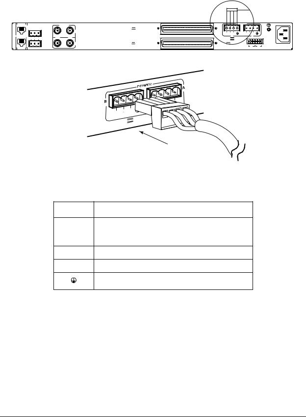
MX2800 M13 Multiplexer User Manual |
Installation and Operation, Section 2 |
||
|
|
|
|
|
|
|
|
|
|
|
|
L |
NONCRITICAL |
A |
|
N |
|
M |
NO COM NC |
O |
|
D |
|
E |
|
M |
|
|
CRITICAL |
DS3/STS-1 |
DSX-1/E1 |
|
(OUT) |
A |
OUT IN
B |
DSX-1/E1 (IN)
|
|
DC POWER |
|
USE COPPER CONDUCTORSONLY! |
PWR – |
B |
PWR – |
A |
|
+ |
+ |
|
||
FAIL |
|
FAIL |
|
|
-48V |
0.7A |
|
|
|
|
|
+24V |
1.5A |
|
|
|
|
|
|
T |
R |
S |
T |
R |
S |
|
|
CLK |
|
|
CLK |
|
|
|
A |
|
|
B |
|
115 AC 50/60Hz
0.8A
PWR |
+ |
|
|
FAIL |
|
-48V |
0.7A |
1.5A |
|
+24V |
|
Figure 2-1. DC Power Connector
Table 2-1. DC Connector Symbol Definitions
Symbol Definition
PWR FAIL Battery backup connector. If the AC fails, a trap is sent to alert user when connected to the 4175043L2 battery backup or equivalent system.
–Negative side of DC power source (usually –48 VDC)
RET Positive side of DC power source (usually ground)
Frame Ground
The following UL requirements must be met during installation of the MX2800 DC version:
1.Disconnect all power sources prior to servicing. Unit may use multiple power sources.
2.Input: Minimum 48 VDC, 0.8 amps
3.Input: Minimum 120 VAC, 0.32 amps
4.Connect to a reliably grounded –48 VDC source which is electrically isolated from the AC source. Use 24 VDC source for 1202289L3.
5.The branch circuit overcurrent protection must be a fuse or circuit breaker rated minimum 48 VDC, maximum 20 amps.
61200290L1-1G |
2-3 |

Section 2, Installation and Operation |
MX2800 M13 Multiplexer User Manual |
|
|
6.A readily accessible disconnect device that is suitably approved and rated must be incorporated in the field wiring.
7.The chassis should be connected to an earth ground using the ground stud located between the AC and DC power sources on the rear panel.
8.The unit must be installed in accordance with the requirements of NEC NFPA 70.
9.The unit must be installed in accordance with Articles 400 and 364.8 of the National Electrical Code NFPA 70 when installed outside of a Restricted Access Location (i.e., Central Office, behind a locked door, service personnel area only).
10. Care should be taken not to upset the stability of the equipment rack after installation is complete.
CAUTION
Use copper conductors only for DC power and ground connection.
5.RACKMOUNT INSTALLATION
The MX2800 can be mounted into a standard 19-inch or 23-inch equipment rack. Follow these steps to mount the unit into a rack:
1. Install the mounting flanges on each side of the MX2800 at one of the three available positions.
CAUTION
Be sure to install the flanges with the screws provided.
2.After the flanges have been installed, position the MX2800 at the correct location within the rack and secure the mounting flanges to the mounting rails of the rack.
3.Make all network, DTE, and power connections to the rear of the unit. Refer to Power Up on page 2-2 for more information on making the DC power connection.
4.Using the 8-position modular to DB-9 female connector and the 8-pin to 8-pin modular cable, connect a VT100 terminal device to the CRAFT port on the front panel of the unit.
NOTE
Two MX2800s can be stacked with out any spacing between the units. ADTRAN recommends 1U (1.75”) of separation above and below the two stacked units. This spacing allows the units to dissipate heat. The design of the MX2800 uses the chassis to distribute heat generated by the unit’s internal cards. This design allows the units to operate without a cooling fan, thus increasing overall reliability of the units.
2-4 |
61200290L1-1G |
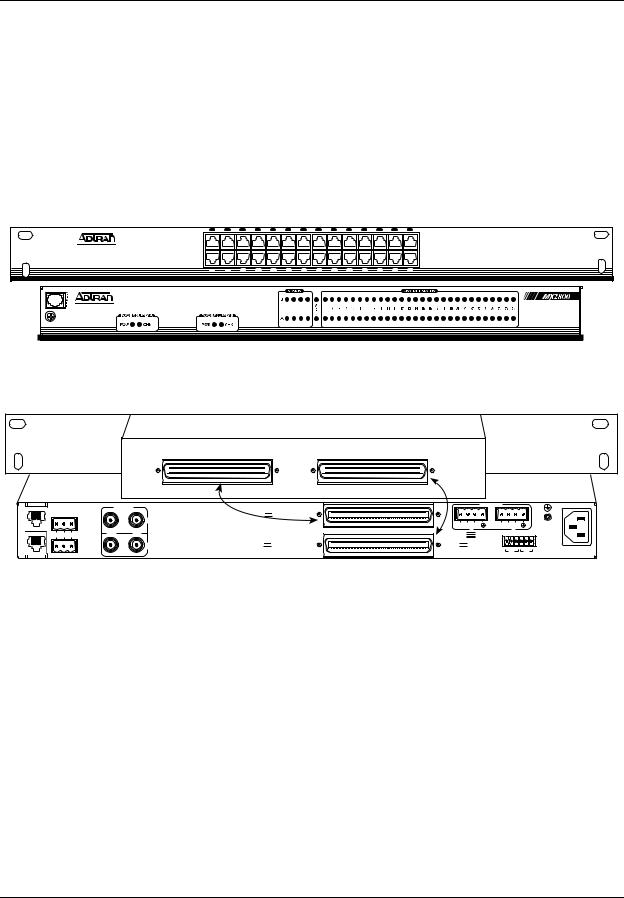
MX2800 M13 Multiplexer User Manual |
Installation and Operation, Section 2 |
Connecting the Breakout Panel
The optional breakout panel (P/N 1200291L1) connects to the MX2800 via the IN and OUT amphenol connectors located on the back of the unit and provides 28 RJ connectors for the individual T1s/E1s. Shipment includes two six-foot, 64-pin to 64-pin amphenol cables for direct cabling to the MX2800. Connect the breakout panel’s IN amphenol connector to the MX2800’s IN amphenol connector and the breakout panel’s OUT amphenol connector to the MX2800’s OUT amphenol connector. See Figure 2-2.
FRONT VIEW
2 |
4 |
6 |
8 |
10 |
12 |
14 |
16 |
18 |
20 |
22 |
24 |
26 |
28 |
1 |
3 |
5 |
7 |
9 |
11 |
13 |
15 |
17 |
19 |
21 |
23 |
25 |
27 |
|
|
|
|
|
|
|
|
|
|
|
|
REAR VIEW
OUT |
|
IN |
|
|
|
Cable 2
L |
|
DS3/STS-1 |
|
|
DSX-1/E1 |
NONCRITICAL |
|
|
|
(OUT) |
|
A |
|
|
|
|
|
N |
|
|
A |
|
|
M |
NO COM NC |
OUT |
IN |
Cable 1 |
|
|
|
|
|||
O |
|
|
|
DSX-1/E1 |
|
M |
|
|
|
||
D |
|
|
|
|
|
E |
|
|
B |
|
|
|
CRITICAL |
|
|
|
(IN) |
Figure 2-2. The Breakout Panel
|
|
DC POWER |
|
USE COPPER CONDUCTORSONLY! |
PWR – |
B |
PWR – |
A |
|
+ |
+ |
|
||
FAIL |
|
FAIL |
|
|
-48V |
0.7A |
|
|
|
|
|
+24V |
1.5A |
|
|
|
|
|
|
T |
R |
S |
T |
R |
S |
|
|
CLK |
|
|
CLK |
|
|
|
A |
|
|
B |
|
115 AC 50/60Hz
0.8A
Connecting the E1 Patch Panel
The optional E1 patch panel (P/N 1200291L5) connects to the MX2800 via the TX and RX amphenol connectors located on the back of the unit and provides 28 pairs of BNC connectors for the individual T1/E1s. Shipment includes two 6-foot, 64-pin to 64-pin amphenol cables for direct cabling to the MX2800. Connect the E1 patch panel’s TX amphenol connector to the MX2800’s IN amphenol connector and the E1 patch panel’s RX amphenol connector to the MX2800's OUT amphenol connector.
61200290L1-1G |
2-5 |
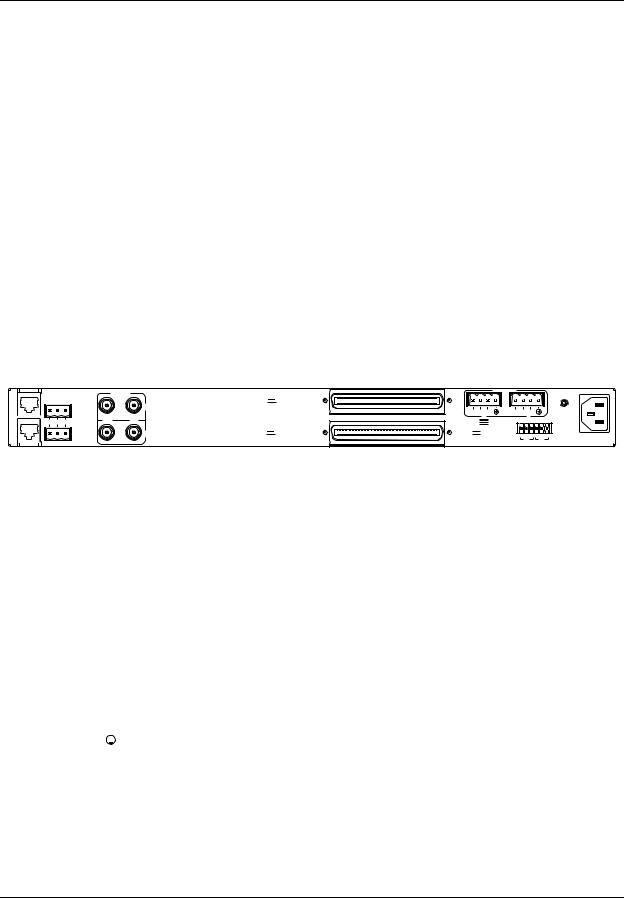
Section 2, Installation and Operation |
MX2800 M13 Multiplexer User Manual |
6.REAR PANEL
The MX2800 rear panel is equipped as follows:
•Ethernet local area network (LAN) port
•Modem port
•Two alarm output terminal blocks
•Two sets of DS-3 in/out jacks
•Two amphenol connectors
•DC/AC power connection
•Ground stud
•Three-prong AC connection
•Wire-wrap pins for external connection of BITS clock (STS-1)
Descriptions for the items shown in Figure 2-3 are explained in Table 2-2. Pin assignments are given in the tables in Appendix B, Pinouts.
N |
1 |
|
3 |
L |
|
NONCRITICAL |
|
A |
|
|
|
M |
2 |
NO COM NC |
|
O |
|
|
|
ME |
|
|
|
D |
|
|
|
|
|
CRITICAL |
|
DS3/STS-1 |
DSX-1/E1 |
|
(OUT) |
A |
OUT IN |
4 |
5 |
B |
DSX-1/E1 (IN)
Figure 2-3. MX2800 Rear View
|
|
|
DC POWER |
|
|
|
|
|
|
CONDUCTORSONLY! |
|
PWR |
– |
B |
6 |
PWR |
– |
A |
|
|
|
USE COPPER |
|
+ |
|
+ |
|
|
|
|
|||||
FAIL |
|
|
|
FAIL |
|
|
|
|
|
|
|
-48V |
|
|
0.7A |
|
|
|
|
|
|
|
|
+24V |
|
|
1.5A |
|
|
|
|
|
|
|
|
|
|
|
|
|
T |
R |
S |
T |
R |
S |
|
|
|
|
|
|
|
CLK |
|
|
CLK |
|
|
|
|
|
|
|
|
A |
|
|
B |
|
|
 7 8
7 8
9
115 AC 50/60Hz
0.8A
Table 2-2. MX2800 Review View Identifiers
# |
Item |
Function |
|||
|
|
|
|
|
|
1 |
Ethernet LAN |
10Base-T Ethernet connection |
|||
|
|
|
|
|
|
2 |
Modem |
Telephone line connection for internal V.34 |
|||
|
|
|
|
|
|
3 |
Noncritical/Critical |
Connections for external audible/visual alarms |
|||
|
|
|
|
|
|
4 |
DS3/STS-1 |
T3 service connection for controller cards A and B |
|||
|
|
|
|
|
|
5 |
DSX-1/E1 |
64-pin female amphenol connectors for T1/E1s |
|||
|
|
|
|
|
|
6 |
Power |
DC power connection |
|||
|
|
|
|
|
|
7 |
|
|
|
|
Ground stud |
|
|
|
|
||
|
|
|
|
||
|
|
|
|
|
|
8 |
115 VAC 50/60 Hz |
AC power connection |
|||
|
|
|
|
|
|
9 |
BITS Clock |
Wire-wrap pins for external connection of BITS clocks |
|||
|
|
|
|
|
|
2-6 |
61200290L1-1G |

MX2800 M13 Multiplexer User Manual |
Installation and Operation, Section 2 |
LAN Port
The LAN port is an 8-pin modular connector that provides a 10Base-T Ethernet LAN interface. This LAN interface is used for SNMP and Telnet control.
NOTE
Connect the LAN port to intra-building wiring only.
Modem Port
The modem port is an 8-pin modular jack that provides a telephone line (POTS) connection for the internal V.34 modem.
NOTE
Information regarding the built-in modem applies to the part numbers 4202290L1, 4202290L2, 4202290L3, and 4202290L4.
The MX2800 can be configured as a dial-in host and also as a dial-out-on-trap device (the unit dials out to a specified host to report error conditions).
Noncritical and Critical Alarm Connectors
The alarm connectors connect to the three contacts of a Form C type relay on the main board of the MX2800. This relay is activated any time the MX2800 detects an alarm condition on the T3 network interface. Both NC (normally closed) and NO (normally open) contacts are provided.
Connect alarms to one of the three-position modular terminal lug connectors. These connectors simplify the initial wiring and connection or disconnection of the alarms when replacing rackmount units. Once a modular connector is wired, push it firmly into the rear panel NONCRITICAL or CRITICAL connector.
The alarm functions can be enabled or disabled through the Alarm Relays section of the Configuration menu. For more information, refer to Alarm Relay Configuration on page 3-33.
DSX-3 Interfaces
The DSX-3 network interfaces are full-duplex circuits provided by four BNC coaxial cable connections (two for each controller card). The receive data from the network is connected to the Rx (IN) connectors, while the transmit data from the MX2800 is connected to the Tx (OUT) connectors. Refer to Section 7, Circuit and Network Redundancy for more specific information about connecting the DS3 interface in redundant and nonredundant systems.
61200290L1-1G |
2-7 |
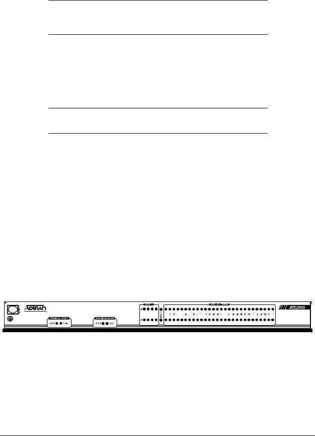
Section 2, Installation and Operation |
MX2800 M13 Multiplexer User Manual |
|
|
NOTE
DSX-3 interfaces must be connected using coaxial cables that have the shields grounded at both ends.
DSX-1/E1 Interfaces
The DSX-1/E1 interfaces are 64-pin amphenol connectors. These interfaces provide Tx and Rx connections between the unit and equipment such as wire-wrap patch panels, punch-down panels, or breakout panels.
NOTE
Connect the DSX-1/E1 interfaces to intra-building wiring only.
Power Connection
The DC power connections are described in Power Up on page 2-2.
7.FRONT PANEL
The MX2800 front panel is shown in Figure 2-4. Descriptions of each part of the front panel follow:
•Craft Port on page 2-8
•ACO Buttons on page 2-15
•Power Supply A/B Status LEDs on page 2-15
•Controller Cards Status LEDs on page 2-15
•T1/E1 Status LEDs on page 2-17
A |
N |
A |
P |
C |
E |
L |
R |
T |
T |
M |
F |
Figure 2-4. MX2800 Front Panel
Craft Port
The craft port, an 8-pin modular jack, provides connection to a VT100 EIA-232 compatible interface (using the supplied 8-pin modular to DB-9 female connector and the 8-pin to 8-pin modular cable).
2-8 |
61200290L1-1G |
Loading...