


 Loading...
ADCP-80-570
Issue 2
March 2006
PowerWorx® Power Distribution Products
Circuit Breaker Panel With Reset Switch
User Manual
20629-A
1361499 Rev A

ADCP-80-570 • Issue 2 • March 2006 • Preface
COPYRIGHT
© 2006, ADC Telecommunications, Inc.
All Rights Reserved
Printed in the U.S.A.
REVISION HISTORY
ISSUE |
DATE |
REASON FOR CHANGE |
1 |
8/2005 |
Original. |
|
|
|
2 |
3/2006 |
Wire colors corrected on Page 28. |
|
|
|
TRADEMARK INFORMATION
ADC and PowerWorx are registered trademarks of ADC Telecommunications, Inc.
DISCLAIMER OF LIABILITY
Contents herein are current as of the date of publication. ADC reserves the right to change the contents without prior notice. In no event shall ADC be liable for any damages resulting from loss of data, loss of use, or loss of profits and ADC further disclaims any and all liability for indirect, incidental, special, consequential or other similar damages. This disclaimer of liability applies to all products, publications and services during and after the warranty period.
This publication may be verified at any time by contacting ADC’s Technical Assistance Center at 1-800-366-3891, extension 73475 (in U.S.A. or Canada) or 952-917-3475 (outside U.S.A. and Canada), or by e-mail to connectivity_tac@adc.com.
ADC Telecommunications, Inc.
P.O. Box 1101, Minneapolis, Minnesota 55440-1101
In U.S.A. and Canada: 1-800-366-3891
Outside U.S.A. and Canada: (952) 938-8080
Fax: (952) 917-1717
Page ii

ADCP-80-570 • Issue 2 • March 2006 • Preface
TABLE OF CONTENTS
Content |
Page |
About This Manual . . . . . . . . . . . . . . . . . . . . . . . . . . . . . . . . . . . . . . . . . . . . . . . . . . . . . . . . . . . . . . . . . . . . . . . . . . . v
Standard Certification . . . . . . . . . . . . . . . . . . . . . . . . . . . . . . . . . . . . . . . . . . . . . . . . . . . . . . . . . . . . . . . . . . . . . . . . . v
Admonishments . . . . . . . . . . . . . . . . . . . . . . . . . . . . . . . . . . . . . . . . . . . . . . . . . . . . . . . . . . . . . . . . . . . . . . . . . . . . . v
General Safety Precautions . . . . . . . . . . . . . . . . . . . . . . . . . . . . . . . . . . . . . . . . . . . . . . . . . . . . . . . . . . . . . . . . . . . . . v
List of Acronyms . . . . . . . . . . . . . . . . . . . . . . . . . . . . . . . . . . . . . . . . . . . . . . . . . . . . . . . . . . . . . . . . . . . . . . . . . . . . .vi
1 PRODUCT DESCRIPTION . . . . . . . . . . . . . . . . . . . . . . . . . . . . . . . . . . . . . . . . . . . . . . . . . . . . . . . . . . . . . . . . . . 1
1.1 Product Functions and Features. . . . . . . . . . . . . . . . . . . . . . . . . . . . . . . . . . . . . . . . . . . . . . . . . . . . . . . . 1
1.2 Panel Components. . . . . . . . . . . . . . . . . . . . . . . . . . . . . . . . . . . . . . . . . . . . . . . . . . . . . . . . . . . . . . . . . 1
1.3 Packaged Hardware . . . . . . . . . . . . . . . . . . . . . . . . . . . . . . . . . . . . . . . . . . . . . . . . . . . . . . . . . . . . . . . . 3
1.4 Power Buses. . . . . . . . . . . . . . . . . . . . . . . . . . . . . . . . . . . . . . . . . . . . . . . . . . . . . . . . . . . . . . . . . . . . . 4
1.5 Input Voltage . . . . . . . . . . . . . . . . . . . . . . . . . . . . . . . . . . . . . . . . . . . . . . . . . . . . . . . . . . . . . . . . . . . . 5
1.6 Input Connectors . . . . . . . . . . . . . . . . . . . . . . . . . . . . . . . . . . . . . . . . . . . . . . . . . . . . . . . . . . . . . . . . . . 5
1.7 Output Voltage . . . . . . . . . . . . . . . . . . . . . . . . . . . . . . . . . . . . . . . . . . . . . . . . . . . . . . . . . . . . . . . . . . . 5
1.8 Output Connectors . . . . . . . . . . . . . . . . . . . . . . . . . . . . . . . . . . . . . . . . . . . . . . . . . . . . . . . . . . . . . . . . . 5
1.9 Chassis Ground Connections . . . . . . . . . . . . . . . . . . . . . . . . . . . . . . . . . . . . . . . . . . . . . . . . . . . . . . . . . . 6
1.10 Circuit Breakers . . . . . . . . . . . . . . . . . . . . . . . . . . . . . . . . . . . . . . . . . . . . . . . . . . . . . . . . . . . . . . . . . . 6
1.11 Power-on Indicators. . . . . . . . . . . . . . . . . . . . . . . . . . . . . . . . . . . . . . . . . . . . . . . . . . . . . . . . . . . . . . . . 6
1.12 Breaker Alarm Indicators . . . . . . . . . . . . . . . . . . . . . . . . . . . . . . . . . . . . . . . . . . . . . . . . . . . . . . . . . . . . 7
1.13 Alarm Operation . . . . . . . . . . . . . . . . . . . . . . . . . . . . . . . . . . . . . . . . . . . . . . . . . . . . . . . . . . . . . . . . . . 7
1.14 Alarm Connections . . . . . . . . . . . . . . . . . . . . . . . . . . . . . . . . . . . . . . . . . . . . . . . . . . . . . . . . . . . . . . . . 7
1.15 Reset Switch. . . . . . . . . . . . . . . . . . . . . . . . . . . . . . . . . . . . . . . . . . . . . . . . . . . . . . . . . . . . . . . . . . . . . 7
1.16 Circuit Breaker Designation Card and Holder. . . . . . . . . . . . . . . . . . . . . . . . . . . . . . . . . . . . . . . . . . . . . . . 7
1.17 Voltage Designation Label . . . . . . . . . . . . . . . . . . . . . . . . . . . . . . . . . . . . . . . . . . . . . . . . . . . . . . . . . . . 8
1.18 Material and Finish . . . . . . . . . . . . . . . . . . . . . . . . . . . . . . . . . . . . . . . . . . . . . . . . . . . . . . . . . . . . . . . . 8
1.19 Cooling . . . . . . . . . . . . . . . . . . . . . . . . . . . . . . . . . . . . . . . . . . . . . . . . . . . . . . . . . . . . . . . . . . . . . . . . 8
1.20 Protective Covers . . . . . . . . . . . . . . . . . . . . . . . . . . . . . . . . . . . . . . . . . . . . . . . . . . . . . . . . . . . . . . . . . 9
1.21 Mounting . . . . . . . . . . . . . . . . . . . . . . . . . . . . . . . . . . . . . . . . . . . . . . . . . . . . . . . . . . . . . . . . . . . . . . . 9
1.22 Specifications . . . . . . . . . . . . . . . . . . . . . . . . . . . . . . . . . . . . . . . . . . . . . . . . . . . . . . . . . . . . . . . . . . . 10
1.23 Dimensions . . . . . . . . . . . . . . . . . . . . . . . . . . . . . . . . . . . . . . . . . . . . . . . . . . . . . . . . . . . . . . . . . . . . 11
2 ACCESSORIES . . . . . . . . . . . . . . . . . . . . . . . . . . . . . . . . . . . . . . . . . . . . . . . . . . . . . . . . . . . . . . . . . . . . . . . . 12 3 UNPACKING AND INSPECTION . . . . . . . . . . . . . . . . . . . . . . . . . . . . . . . . . . . . . . . . . . . . . . . . . . . . . . . . . . . . . 12 4 INSTALLATION . . . . . . . . . . . . . . . . . . . . . . . . . . . . . . . . . . . . . . . . . . . . . . . . . . . . . . . . . . . . . . . . . . . . . . . . 12 4.1 Installation Tools Required . . . . . . . . . . . . . . . . . . . . . . . . . . . . . . . . . . . . . . . . . . . . . . . . . . . . . . . . . . 13 4.2 Materials Required . . . . . . . . . . . . . . . . . . . . . . . . . . . . . . . . . . . . . . . . . . . . . . . . . . . . . . . . . . . . . . . 13 4.3 Pre-Installation Testing . . . . . . . . . . . . . . . . . . . . . . . . . . . . . . . . . . . . . . . . . . . . . . . . . . . . . . . . . . . . 13 4.4 Cable Management Bar (Optional Accessory) . . . . . . . . . . . . . . . . . . . . . . . . . . . . . . . . . . . . . . . . . . . . . 16 4.5 Mounting Panel on Rack. . . . . . . . . . . . . . . . . . . . . . . . . . . . . . . . . . . . . . . . . . . . . . . . . . . . . . . . . . . . 16 4.6 Installing Designation Cards . . . . . . . . . . . . . . . . . . . . . . . . . . . . . . . . . . . . . . . . . . . . . . . . . . . . . . . . . 18 4.7 Installing Voltage Designation Label . . . . . . . . . . . . . . . . . . . . . . . . . . . . . . . . . . . . . . . . . . . . . . . . . . . 18 4.8 Installing Ground Wires . . . . . . . . . . . . . . . . . . . . . . . . . . . . . . . . . . . . . . . . . . . . . . . . . . . . . . . . . . . . 18 4.9 Connecting Alarms . . . . . . . . . . . . . . . . . . . . . . . . . . . . . . . . . . . . . . . . . . . . . . . . . . . . . . . . . . . . . . . 19
Page iii
© 2006, ADC Telecommunications, Inc.

ADCP-80-570 • Issue 2 • March 2006 • Preface
TABLE OF CONTENTS
Content |
Page |
4.10 Connecting Output. . . . . . . . . . . . . . . . . . . . . . . . . . . . . . . . . . . . . . . . . . . . . . . . . . . . . . . . . . . . . . . . 20
4.11 Connecting Input. . . . . . . . . . . . . . . . . . . . . . . . . . . . . . . . . . . . . . . . . . . . . . . . . . . . . . . . . . . . . . . . . 21
4.12 Installing Protective Covers . . . . . . . . . . . . . . . . . . . . . . . . . . . . . . . . . . . . . . . . . . . . . . . . . . . . . . . . . 23
5 TESTING . . . . . . . . . . . . . . . . . . . . . . . . . . . . . . . . . . . . . . . . . . . . . . . . . . . . . . . . . . . . . . . . . . . . . . . . . . . . 24 5.1 Testing Power Indicators and Connection Polarity . . . . . . . . . . . . . . . . . . . . . . . . . . . . . . . . . . . . . . . . . . 24 5.2 Testing Alarm Contacts Normal State . . . . . . . . . . . . . . . . . . . . . . . . . . . . . . . . . . . . . . . . . . . . . . . . . . . 24
6 OPERATION . . . . . . . . . . . . . . . . . . . . . . . . . . . . . . . . . . . . . . . . . . . . . . . . . . . . . . . . . . . . . . . . . . . . . . . . . . 25
6.1 Connecting New Equipment . . . . . . . . . . . . . . . . . . . . . . . . . . . . . . . . . . . . . . . . . . . . . . . . . . . . . . . . . 25
6.2 Using the Reset Switch . . . . . . . . . . . . . . . . . . . . . . . . . . . . . . . . . . . . . . . . . . . . . . . . . . . . . . . . . . . . 26
7 MAINTENANCE . . . . . . . . . . . . . . . . . . . . . . . . . . . . . . . . . . . . . . . . . . . . . . . . . . . . . . . . . . . . . . . . . . . . . . . . 26
7.1 Performing a Routine Inspection . . . . . . . . . . . . . . . . . . . . . . . . . . . . . . . . . . . . . . . . . . . . . . . . . . . . . . 26
7.2 Replacing a Circuit Breaker . . . . . . . . . . . . . . . . . . . . . . . . . . . . . . . . . . . . . . . . . . . . . . . . . . . . . . . . . 26
8 CUSTOMER INFORMATION AND ASSISTANCE. . . . . . . . . . . . . . . . . . . . . . . . . . . . . . . . . . . . . . . . . . . . . . . . . . . 29 A ALLOWABLE AMPACITIES OF INSULATED CONDUCTORS . . . . . . . . . . . . . . . . . . . . . . . . . . . . . . . . . . . . . . . . . . . 31
Page iv
© 2006, ADC Telecommunications, Inc.

ADCP-80-570 • Issue 2 • March 2006 • Preface
ABOUT THIS MANUAL
This manual describes the PowerWorx Circuit Breaker Panel With Reset Switch, and provides all information required to install, test, and operate this product.
STANDARD CERTIFICATION
The panel conforms to the applicable requirements of the following: UL/CSA/EN 60950, FCC Part 15, CISPR 22, and CISPR 24.
ADMONISHMENTS
Important safety admonishments are used throughout this manual to warn of possible hazards to persons or equipment. An admonishment identifies a possible hazard and then explains what may happen if the hazard is not avoided. The admonishments — in the form of Dangers, Warnings, and Cautions — must be followed at all times. These warnings are flagged by use of the triangular alert icon (seen below), and are listed in descending order of severity of injury or damage and likelihood of occurrence.
Danger: Danger is used to indicate the presence of a hazard that will cause severe personal injury, death, or substantial property damage if the hazard is not avoided.
Warning: Warning is used to indicate the presence of a hazard that can cause severe personal injury, death, or substantial property damage if the hazard is not avoided.
Caution: Caution is used to indicate the presence of a hazard that will or can cause minor personal injury or property damage if the hazard is not avoided.
GENERAL SAFETY PRECAUTIONS
-
Warning: The circuit breaker panel uses electrical voltage and current levels that may be considered an energy hazard. Only qualified personnel should be allowed to install, operate, maintain, or otherwise come into contact with this equipment when energized. Only insulated tools should be used on energized elements of the panel.
Warning: Disconnect or turn off the power before connecting the input or output wires on the circuit breaker panel. This may require turning off the system office battery input at the battery distribution fuse bay or turning off the circuit breakers at the panel.
Warning: Wet conditions increase the potential for receiving an electrical shock when installing or using electrically-powered equipment. To prevent electrical shock, never install or use electrical equipment in a wet location or during a lightning storm.
Page v
© 2006, ADC Telecommunications, Inc.

ADCP-80-570 • Issue 2 • March 2006 • Preface
Warning: To prevent the system from overheating, do not operate it in an area that exceeds the maximum recommended ambient temperature of 55º C.
Warning: Stability hazard. The rack stabilizing mechanism must be in place, or the rack must be bolted to the floor before you slide the unit out for servicing. Failure to stabilize the rack can cause the rack to tip over.
Warning: Suitable for mounting on concrete or other non-combustible surface only.
Warning: Take care when connecting units to the supply circuit so that wiring is not overloaded.
LIST OF ACRONYMS
LED -- Light-Emitting Diode
Page vi
© 2006, ADC Telecommunications, Inc.

ADCP-80-570 • Issue 2 • March 2006
1 PRODUCT DESCRIPTION
This section describes the PowerWorx Circuit Breaker Panel With Reset Switch. Topics include product functions and features, panel components, packaged hardware, power buses, input voltage, input connectors, output voltage, output connectors, chassis ground connections, circuit breakers, power on indicators, breaker alarm indicators, alarm operation, alarm connections, reset switch, circuit breaker designation card and holder, voltage designation label, material and finish, cooling, protective covers, mounting, specifications, and dimensions.
1.1Product Functions and Features
The Circuit Breaker Panel With Reset Switch supplies low-voltage, protected dc power to –24 Vdc or –48 Vdc powered equipment installed in a central office, multimedia headend, remote site, or other restricted access location. The panel provides the following functions and features:
•Two side-by-side power buses, designated A and B, each with seven power outputs.
•Fourteen circuit breakers (seven per bus). Each bus has two 10 Amp circuit breakers and five 5 Amp circuit breakers.
•Maximum input rating of 45 Amps per bus. This corresponds to a maximum input rating of 90 Amps for the total panel.
•One Power On LED (green) and one Breaker Alarm LED (red) for each bus.
•One Reset switch for the total panel. The Reset switch allows the operator to reset the panel to a non-alarming state if a breaker has been turned off or tripped due to an overcurrent condition.
•Alarm contacts (screw-down barrier terminal strips) for remote reporting of an alarm condition. The alarm contacts can be used to open or close a loop connected to an external alarm system.
•Mounting brackets providing the ability to mount the panel in a 19-inch (482.6 mm) or 23inch (584.2 mm) WECO or EIA equipment rack. The panel occupies one rack space (1.75 inches, 44.4 mm).
Note: The panel requires one open rack space above the chassis and one open rack space below the chassis for heat dissipation.
•Two-hole compression-lug style terminals for input power connections.
•Screw-down barrier terminal strips for output power connections.
•Two chassis ground studs.
•Easy to remove rear protective covers. These covers mount over the input and output power connections to prevent inadvertent contact.
1.2Panel Components
Figure 1 shows the components of the circuit breaker panel.
Page 1
© 2006, ADC Telecommunications, Inc.

ADCP-80-570 • Issue 2 • March 2006
BUS A |
RESET |
|
|
|
1 TO 7 CIRCUIT BREAKERS |
|
|
||
SWITCH |
|
|
||
|
|
|
||
|
|
|
BUS B |
|
BUS A |
|
|
POWER-ON |
|
|
|
INDICATOR |
||
POWER-ON |
BUS A ALARM |
|||
(GREEN LED) |
||||
INDICATOR |
||||
INDICATOR (RED LED) |
||||
|
||||
(GREEN LED) |
|
|||
|
|
BUS B |
||
|
|
|
||
FRONT VIEW |
|
1 TO 7 CIRCUIT BREAKERS |
||
BUS B ALARM |
||||
|
|
INDICATOR (RED LED) |
||
DESIGNATION CARD
AND CARD HOLDER
BUS B INPUT |
|
|
|
|
POWER TERMINALS |
ALARM |
|
|
|
|
|
|
||
|
TERMINALS |
|
|
|
BUS B OUTPUT |
|
|
BUS A OUTPUT |
|
|
POWER TERMINALS |
|||
POWER TERMINALS |
CHASSIS |
|
|
|
|
|
|
|
|
|
|
GROUNDING |
BUS A INPUT |
|
|
|
STUDS |
|
POWER TERMINALS |
COVER FOR
INPUT POWER
TERMINALS
COVER FOR
OUTPUT POWER
TERMINALS
REAR VIEW COVER FOR 20631-A
INPUT POWER
TERMINALS
Figure 1. Circuit Breaker Panel Components
Page 2
© 2006, ADC Telecommunications, Inc.
ADCP-80-570 • Issue 2 • March 2006
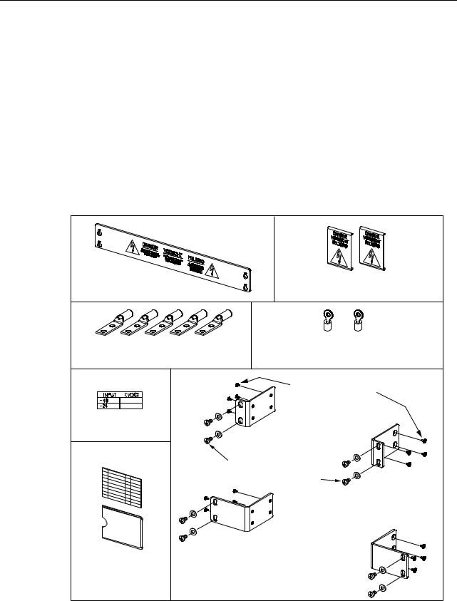
1.3Packaged Hardware
The shipped product includes hardware components that are packaged separately and shipped in the carton with the basic panel. Figure 2 shows the shipped items:
•5/16-inch long, Phillips drive, 8-32 flat-head screws (8)—Used to secure the mounting brackets to the panel.
•3/8-inch long, combination drive, 12-24 pan-head screws (4) and #12 flat washers (4)— Used to secure the panel mounting brackets to the equipment rack.
•#10 ring terminals (2) for #12–#10 AWG wire—Can be used to connect the grounding cables to the grounding studs.
•2-Hole Lugs for #6 AWG wire (4)—Used to connect input power cable to input power terminal blocks.
REAR COVER FOR OUTPUT |
REAR COVERS FOR INPUT |
|
POWER TERMINAL BLOCK |
||
POWER/ALARM TERMINAL BLOCK |
||
|
||
2-HOLE LUGS FOR |
#10 RING TERMINALS FOR |
|
6 AWG WIRE |
12-10 AWG WIRE |
|
|
5/16-INCH (7.936 MM) 8-32 |
|
|
FLAT-HEAD SCREWS |
|
VOLTAGE |
|
|
LABEL |
ORIENTATION FOR |
|
|
19-INCH RACK INSTALLATION |
|
|
3/8-INCH (9.525 MM) 12-24 |
|
|
SCREWS AND #12 WASHERS |
|
|
ORIENTATION FOR |
|
|
23-INCH RACK INSTALLATION |
|
DESIGNATION CARD |
UNIVERSAL MOUNTING BRACKETS |
|
AND CARD HOLDER |
||
|
AND SCREWS |
|
|
20633-A |
Figure 2. Packaged Hardware
Page 3
© 2006, ADC Telecommunications, Inc.
ADCP-80-570 • Issue 2 • March 2006
•Rear protective input terminal covers (2) and output/alarm terminal cover (1)—Used to prevent accidental contact with the alarm and power terminals.
•#6-32 Screws (4)—Used to fasten output/alarm terminal cover to rear of panel chassis.
•Designation card and card holder (1)—Used to record information about the protected equipment. Cards and clear cover insert into the card holder.
•Voltage label (1)—Used to indicate whether the input voltage is –48 or –24 Vdc.
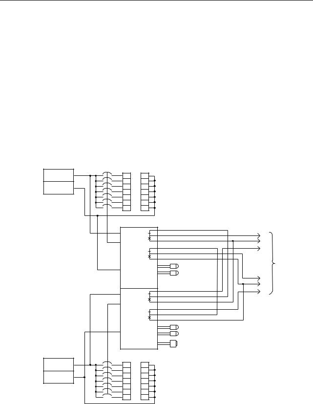
1.4Power Buses
Each circuit breaker panel has two isolated power buses. Each bus distributes the input power to the output power circuits. In each bus circuit, current flows from the input power bus, through the circuit breaker, to the output power circuit. The current capacity of each bus is 45 Amps maximum. Figure 3 is a block diagram of the power buses.
–24V/–48V
BATTERY A
RETURN A
–24V/–48V
BATTERY B
RETURN B
BATTERY RETURN
1
2
3
4
5
6
7
BUS A |
|
C |
|
|
|
FA |
|
NO |
|
|
|
|
|
NC |
|
|
SYSTEM ALARM |
RETURN A |
POWER A LED |
CONNECTIONS |
BREAKER |
|
|
|
|
|
|
ALARM A LED |
C |
|
|
NO |
BUS B |
|
NC |
|
|
|
FB |
|
|
RETURN B |
POWER B LED |
|
BREAKER ALARM B LED |
|
|
|
|
|
|
ALARM RESET PUSHBUTTON |
|
BATTERY RETURN
1
2
3
4
5
6
7
20691-A
Figure 3. Circuit Breaker Panel Block Diagram
Page 4
© 2006, ADC Telecommunications, Inc.
ADCP-80-570 • Issue 2 • March 2006
Each of the power buses supports seven circuit breaker positions including two 10 Amp circuit breaker positions and five 5 Amp circuit breaker positions giving a total capacity per bus of 45 Amps.
When a circuit breaker trips, the input power bus is disconnected from the corresponding output circuit.
1.5Input Voltage
The dual bus circuit breaker panel can accommodate either –24 Vdc on both buses or –48 Vdc on both buses.
Warning: Use of one bus only on a dual bus panel will result in false alarms for the unused bus. Power is required on both buses on a dual bus panel for normal operation.
The voltage level is sensed by the circuit breaker panel circuitry. The input voltages used with the circuit breaker panel can fall within the following ranges:
•–24 Vdc nominal, within range of –21 Vdc to –30 Vdc
•–48 Vdc nominal, within range of –42 Vdc to –56 Vdc
1.6Input Connectors
Each power bus has two input connectors on the rear of the circuit breaker panel through which input power is provided. The two input power connectors are labeled “BATT” (battery) and “RTN” (return). Each input connector consists of a pair of 0.25-inch (0.635 cm) studs (with nuts) mounted on a plastic terminal block. Each pair of studs can accept different size 2-hole compression lugs used with a range of wire sizes up to #6 AWG copper wire. Two 2-hole lugs per bus for use with #6 AWG wire (four total) are provided with the circuit breaker panel. Additional lugs are available as accessory items. Maximum lug width is 0.62 inches (1.6 cm). In selecting the copper wire size to be used for power input, consider the allowable ampacity as defined by local practice and the National Electrical Code (refer to Appendix A).
1.7Output Voltage
The output voltage will be the same as the applied input voltage.
1.8Output Connectors
Each bus has two screw-down terminal strips with seven 8-32 screws each on the back of the panel. The upper terminal strip contains the BATT (power feed) connectors. The lower terminal strip contains the RTN (return) connectors. When a piece of equipment is connected to the circuit breaker panel, it is connected to one BATT connector and one RTN connector located vertically above and below one another.
Page 5
© 2006, ADC Telecommunications, Inc.

ADCP-80-570 • Issue 2 • March 2006
The individual terminals are on 0.375 inch (9.525 mm) centers with a distance between barriers of 0.32 inch (81.3 mm). The terminals can accept a variety of wire sizes up to #12 AWG with crimp-on spade lug connectors or wires in sizes from #12 AWG to #22 AWG with the insulation stripped back. The connectors or wires are inserted under the screws in the terminal strip, and the screws are tightened down.
In selecting the copper wire size to be used for power output, consider the allowable ampacity as defined by local practice and the National Electrical Code (refer to Appendix A).
1.9Chassis Ground Connections
Two #10 studs (with nuts) are provided for grounding the circuit breaker panel chassis. The studs are mounted on 0.625 inch (15.875 mm) centers, and can accommodate a 2-hole compression lug. Two crimp ring lug terminals for use with two #10 AWG wires are provided with the circuit breaker panel.
1.10 Circuit Breakers
The circuit breakers are magnetic actuation, manual reset, single pole, replaceable, 60 Vdc rated circuit breakers, with finger guard and amperage markings. Each power bus has two 10 Amp breakers and five 5 Amp breakers. The maximum capacity per bus is 45 Amps.
The circuit breakers are of the type called “short delay.” The trip times of short delay circuit breakers are a function of the percent of rated current, as indicated in Table 1. The circuit breaker will trip (open) and the switch will move to the off position (bottom pushed in) when the circuit current exceeds the capacity of the circuit breaker. To reset a circuit breaker, push the switch to the on position (top pushed in).
Circuit breakers are field-replaceable. Please contact ADC Technical Support if replacement is required (refer to Section 8, Customer Information and Assistance, on page 29).
Table 1. Short Delay Trip Times in Seconds
PERCENT OF RATED CURRENT
100% |
135% |
150% |
200% |
400% |
600% |
800% |
1000% |
1200% |
NO |
.300- |
.200- |
.100- |
.030- |
.008- |
.006- |
.005- |
.005- |
TRIP |
7.00 |
5.00 |
2.00 |
.500 |
.300 |
.150 |
.100 |
.100 |
|
|
|
|
|
|
|
|
|
1.11 Power-on Indicators
A green LED Power On indicator for each power bus is mounted on the front panel of the circuit breaker panel. If the LED indicator is on, power is being applied to the bus input connectors. If the green LED indicator is off, power is not being applied to the bus input connectors.
Page 6
© 2006, ADC Telecommunications, Inc.
Loading...