


AD-200 Phase 7
Non-Tilt
Service Manual
American Dryer Corporation
88 Currant Road
Fall River, MA 02720-4781
Telephone: (508) 678-9000 / Fax: (508) 678-9447
E-mail: techsupport@amdry.com
www.amdry.com
050801DMG/calbert |
ADC Part No. 450034 |

Retain This Manual In A Safe Place For Future Reference
American Dryer Corporation products embody advanced concepts in engineering, design, and safety. If this product is properly maintained, it will provide many years of safe, efficient, and trouble-free operation.
ONLY qualified technicians should service this equipment.
OBSERVE ALL SAFETY PRECAUTIONS displayed on the equipment or specified in the installation manual included with the dryer.
The following “FOR YOUR SAFETY” caution must be posted near the dryer in a prominent location.
FOR YOUR SAFETY |
POUR VOTRE SÉCURITÉ |
Do not store or use gasoline or other flammable vapors or liquids in the vicinity of this or any other appliance.
Ne pas entreposer ni utiliser d’essence ni d’autres vapeurs ou liquides inflammables dans le voisinage de cet appareil ou de yout autre appareil.
We have tried to make this manual as complete as possible and hope you will find it useful. ADC reserves the right to make changes from time to time, without notice or obligation, in prices, specifications, colors, and material, and to change or discontinue models.
|
Important |
|
For your convenience, log the following information: |
|
AD-200 Phase 7 Non-Tilt |
DATE OF PURCHASE ____________________________ MODEL NO. __________________________________________ |
|
RESELLER’S NAME |
_______________________________________________________________________________________ |
Serial Number(s) |
________________________________________________________________________________________ |
|
________________________________________________________________________________________ |
|
________________________________________________________________________________________ |
Replacement parts can be obtained from your reseller or the ADC factory. When ordering replacement parts from the factory, you can FAX your order to ADC at (508) 678-9447 or telephone your order directly to the ADC Parts Department at (508) 678-9000. Please specify the dryer model number and serial number in addition to the description and part number, so that your order is processed accurately and promptly.
The illustrations on the following pages may not depict your particular dryer exactly. The illustrations are a composite of the various dryer models. Be sure to check the descriptions of the parts thoroughly before ordering.
“IMPORTANT NOTE TO PURCHASER”
Information must be obtained from your local gas supplier on the instructions to be followed if the user smells gas. These instructions must be posted in a prominent location near the dryer.

IMPORTANT
YOU MUST DISCONNECT AND LOCKOUT THE ELECTRIC SUPPLY AND THE GAS SUPPLY OR THE STEAM SUPPLY BEFORE ANY COVERS OR GUARDS ARE REMOVED FROM THE MACHINE TO ALLOW ACCESS FOR CLEANING, ADJUSTING, INSTALLATION, OR TESTING OF ANY EQUIPMENT PER OSHA (Occupational Safety and Health Administration) STANDARDS.
FOR YOUR SAFETY
DO NOT STORE OR USE GASOLINE OR OTHER FLAMMABLE VAPOR AND LIQUIDS IN THE VICINITY OF THIS OR ANY OTHER APPLIANCE.
DO NOT DRY MOP HEADS IN THE DRYER.
DO NOT USE DRYER IN THE PRESENCE OF DRY CLEANING FUMES.
CAUTION
DRYERS SHOULD NEVER BE LEFT UNATTENDED WHILE IN OPERATION.
WARNING
CHILDREN SHOULD NOT BE ALLOWED TO PLAY ON OR NEAR THE DRYERS.
CHILDREN SHOULD BE SUPERVISED IF NEAR DRYER(S) IN OPERATION.
WARNING
The dryer must never be operated with any of the back guards, outer tops, or service panels removed. PERSONAL INJURY OR FIRE COULD RESULT.

WARNING
DRYER MUST NEVER BE OPERATED WITHOUT THE LINT FILTER OR SCREEN IN PLACE, EVEN IF AN EXTERNAL LINT COLLECTION SYSTEM IS USED.
IMPORTANT
PLEASE OBSERVE ALL SAFETY PRECAUTIONS displayed on the equipment and specified in the installation manual included with the dryer.
The wiring diagram for the dryer is located in the front electrical control box area.
Table of Contents
AD-200 REFERENCE GUIDE (Basket [Tumbler] Section) |
.............................. 3 |
|
AD-200 REFERENCE GUIDE (Base Section) ................................................... |
4 |
|
SECTION I |
|
|
SAFETY PRECAUTIONS ................................................................................... |
5 |
|
SECTION II |
|
|
ROUTINE MAINTENANCE .............................................................................. |
7 |
|
A. Cleaning ..................................................................................................................................... |
7 |
|
B. |
Lubrication ................................................................................................................................. |
9 |
C. Adjustments ............................................................................................................................. |
10 |
|
SECTION III |
|
|
SPECIFICATIONS AND DIMENSIONS ......................................................... |
11 |
|
A. Specifications (Gas and Steam Models) ..................................................................................... |
11 |
|
B. Dimensions ............................................................................................................................... |
12 |
|
SECTION IV |
|
|
INSTALLATION REQUIREMENTS ............................................................... |
13 |
|
A. Enclosure/Air Supply/Exhaust Requirements .............................................................................. |
13 |
|
B. Electrical and Gas Requirements ............................................................................................... |
14 |
|
C. Operational Service Check Procedure ...................................................................................... |
14 |
|
SECTION V |
|
|
COMPONENT DESCRIPTION/REPLACEMENT ........................................ |
15 |
|
A. Heat Section............................................................................................................................. |
15 |
|
B. Troubleshooting The Direct Spark Ignition (DSI) System ........................................................... |
21 |
|
C. Natural Gas and Liquid Propane (L.P.) Gas Conversion Instructions .......................................... |
38 |
|
D. Steam Coil System Operation ................................................................................................... |
39 |
|
E. |
Sprinkler System Description .................................................................................................... |
44 |
F. |
Air Jet Assembly....................................................................................................................... |
50 |
G. Blower (Squirrel Cage Fan) Motor Assembly ............................................................................ |
52 |
|
H. Filter/Regulator Assembly ......................................................................................................... |
59 |
|
I. |
Door Systems ........................................................................................................................... |
60 |
J. Control and Electrical System ................................................................................................... |
65 |
|
K. Basket (Tumbler) System .......................................................................................................... |
76 |
|
SECTION VI |
|
PROCEDURE FOR FUNCTIONAL CHECK |
|
OF REPLACEMENT COMPONENTS ........................................................... |
86 |
SECTION VII |
|
PHASE 7 OPL SYSTEM DIAGNOSTICS ....................................................... |
88 |
A. Diagnostic (L.E.D. Display) Fault Messages ............................................................................... |
88 |
B. I/O Board Input and Output L.E.D. Indicators .......................................................................... |
90 |
SECTION VIII |
|
TROUBLESHOOTING ..................................................................................... |
95 |

AD-200 Reference Guide
(Basket [Tumbler] Section)
3
AD-200 Reference Guide
(Base Section)
4

SECTION I
SAFETY PRECAUTIONS
CAUTION: The dryer should never be left unattended while in operation.
WARNING: For your safety, the information in this manual must be followed to minimize the risk of fire or explosion or to prevent property damage, personal injury, or loss of life.
WARNING: The dryer must never be operated with any of the back guards, outer tops, or service panels removed. PERSONAL INJURY OR FIRE COULD RESULT.
1.DO NOT store or use gasoline or other flammable vapors and liquids in the vicinity of this or any other appliance.
2.Purchaser/user should consult the local gas supplier for proper instructions to be followed in the event the user smells gas. The instructions should be posted in a prominent location.
3.WHAT TO DO IF YOU SMELL GAS...
a.DO NOT try to light any appliance.
b.DO NOT touch any electrical switch.
c.DO NOT use any phone in your building.
d.Clear the room, building, or area of ALL occupants.
e.Immediately call your gas supplier from a neighbor’s phone. Follow the gas supplier’s instructions.
f.If you cannot reach your gas supplier, call the fire department.
4.Installation and service must be performed by a qualified installer, service agency, or gas supplier.
5.Dryer(s) must be exhausted to the outdoors.
6.Although ADC produces a very versatile dryer, there are some articles that, due to fabric composition or cleaning method, should not be dried in it.
WARNING: Dry only water washed fabrics. DO NOT dry articles spotted or washed in dry cleaning solvents, a combustible detergent, or “all purpose” cleaner.
EXPLOSION COULD RESULT.
WARNING: DO NOT dry rags or articles coated or contaminated with gasoline, kerosene, oil, paint, or wax.
EXPLOSION COULD RESULT.
5

WARNING: DO NOT dry mop heads. Contamination by wax or flammable solvents will create a fire hazard.
WARNING: DO NOT use heat for drying articles that contain plastic, foam, sponge rubber, or similarly textured rubber materials. Drying in a heated basket (tumbler) may damage plastics or rubber and may be a fire hazard.
7.A program should be established for the inspection and cleaning of lint in the burner area, exhaust ductwork, and area around the back of the dryer. The frequency of inspection and cleaning can best be determined from experience at each location.
WARNING: The collection of lint in the burner area and exhaust ductwork can create a potential fire hazard.
8.For personal safety, the dryer must be electrically grounded in accordance with local codes and/or the National Electrical Code ANSI/NFPA NO. 70-LATEST EDITION or in Canada, the Canadian Electrical Codes Parts 1 & 2 CSA C22.1-1990 or LATEST EDITION.
NOTE: Failure to do so will VOID THE WARRANTY.
9.UNDER NO CIRCUMSTANCES should the dryer door switches, lint drawer switch, or heat safety circuit ever be disabled.
WARNING: PERSONAL INJURY OR FIRE COULD RESULT.
10.This dryer is not to be used in the presence of dry cleaning solvents or fumes.
11.Remove articles from the dryer as soon as the drying cycle has been completed.
WARNING: Articles left in the dryer after the drying and cooling cycles have been completed can create a fire hazard.
12.READ AND FOLLOW ALL CAUTION AND DIRECTION LABELS ATTACHED TO THE DRYER.
WARNING: YOU MUST DISCONNECT AND LOCKOUT THE ELECTRIC SUPPLY AND THE GAS SUPPLY OR THE STEAM SUPPLY BEFORE ANY COVERS OR GUARDS ARE REMOVED FROM THE MACHINE TO ALLOW ACCESS FOR CLEANING, ADJUSTING, INSTALLATION, OR TESTING OF ANY EQUIPMENT PER OSHA (Occupational Safety and Health Administration)
STANDARDS.
IMPORTANT: Label ALL wires prior to disconnection when servicing the microprocessor controller (computer) and the ignition module. WIRING ERRORS CAN CAUSE
IMPROPER AND DANGEROUS OPERATION.
6
SECTION II
ROUTINE MAINTENANCE
A. CLEANING
A schedule should be established for periodic inspection, cleaning, and removal of lint from various areas of the dryer, as well as throughout the ductwork system. The frequency of cleaning can best be determined from experience at each location. Maximum operating efficiency is dependent upon proper air circulation. The accumulation of lint can restrict this airflow. If the guidelines in this section are met, an ADC dryer will provide many years of efficient, trouble free, and most importantly safe operation.
WARNING: LINT FROM MOST FABRICS IS HIGHLY COMBUSTIBLE. THE ACCUMULATION OF LINT CAN CREATE A POTENTIAL FIRE HAZARD.
WARNING: KEEP DRYER AREA CLEAR AND FREE FROM COMBUSTIBLE MATERIALS, GASOLINE, AND OTHER FLAMMABLE VAPORS AND LIQUIDS.
NOTE: REMOVE POWER FROM THE DRYER BEFORE PERFORMING ANY MAINTENANCE IN THE DRYER.
NOTE: Suggested time intervals shown are for average usage, which is considered six (6) to eight (8) operational (running) hours per day.
SUGGESTED CLEANING SCHEDULE
EVERY THIRD OR FOURTH LOAD
Clean the lint screen. A clogged lint screen will cause poor dryer performance. The lint screen is located in the lint drawer in the base of the dryer. Pull out the lint drawer, brush the lint off the lint screen, and remove the lint. Inspect the lint screen and replace if torn.
NOTE: The frequency of cleaning the lint screens can best be determined from experience at each location.
WEEKLY
Open the hinged panels on each side of the basket (tumbler) section and remove any lint accumulation from the basket (tumbler) drive motor, drive shafts, gear (speed) reducer, drive belts, drive wheels, and drive shaft bearings.
Slide the lint basket ALL the way out of the dryer and clean any lint accumulation off the temperature sensor bracket, which is located above the lint basket.
7
WARNING: TO AVOID THE HAZARD OF ELECTRICAL SHOCK, DISCONTINUE ELECTRICAL SUPPLY TO THE DRYER.
MONTHLY
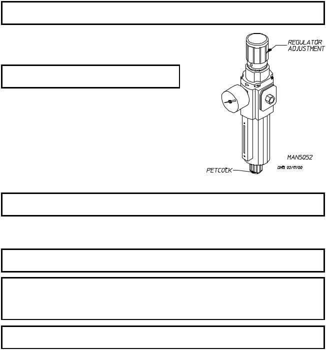
Empty the compressed air filter bowl.
NOTE: REGULATOR PRESSURE IS TO BE SET
AT 80 PSI (5.51 BARS).
Clean any lint accumulation from the gas valve and burner area at the top of the dryer, the fan (squirrel cage fan) motor, and the fan (squirrel cage fan) bearings located in the dryer base.
EVERY 6 MONTHS
STEAM MODELS - Clean the steam coil fins. We suggest using compressed air and a vacuum cleaner with brush attachment.
NOTE: When cleaning steam coil fins, be careful not to bend the fins. If fins are bent, straighten by using a fin comb, which is available from any local air conditioning supply house.
Inspect and remove any lint accumulation in customer furnished exhaust ductwork system and from the dryer’s internal exhaust ducting.
NOTE: THE ACCUMULATION OF LINT IN THE EXHAUST DUCTWORK CAN CREATE A POTENTIAL FIRE HAZARD.
NOTE: DO NOT OBSTRUCT THE FLOW OF COMBUSTION AND VENTILATION AIR. CHECK CUSTOMER FURNISHED BACK DRAFT DAMPERS IN THE EXHAUST DUCTWORK. INSPECT AND REMOVE ANY LINT ACCUMULATION, WHICH CAN CAUSE THE DAMPER TO BIND OR STICK.
NOTE: When cleaning the dryer cabinets, avoid using harsh abrasives. A product intended for the cleaning of appliances is recommended.
Clean off any lint accumulation on top of the temperature probe and the hi-limit switch located above the lint basket.
8
B. LUBRICATION
MONTHLY
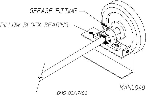
The two (2) bearings that support the squirrel cage fan shaft must be lubricated. Use Shell Alvania #2 grease or its equivalent. Generically, this grease would be described as an NLGI Grade 2 multipurpose industrial grease with a lithium thickener and mineral base oil.
EVERY 3 MONTHS
The four (4) bearings that support the drive and idler shafts must be lubricated. Use Shell Alvania #2 grease or its equivalent. Generically, this grease would be described as an NLGI Grade 2 multipurpose industrial grease with a lithium thickener and mineral base oil.
9
EVERY 6 MONTHS
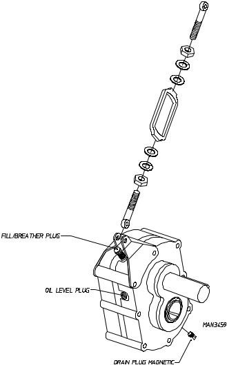
Change gear oil in basket (tumbler) shaft gear (speed) reducer.
1.Remove the drain plug (located at the bottom rear of the reducer).
2.After oil is completely drained, replace the drain plug.
3.Remove the vent plug and pour in 1.4 liters of Mobil Oil DTE HH5G (I.S.O. viscosity grade 460), SAE 90, or its equivalent.
C. ADJUSTMENTS
7 DAYS AFTER INSTALLATION AND EVERY 6 MONTHS THEREAFTER
Inspect bolts, nuts, screws, (bearing setscrews), grounding connecitons, and nonpermanent gas connections (unions, shutoff valves, and orifices). Fan (squirrel cage fan) V-belts, along with the motor and drive belts should be examined and replaced if necessary. Tighten loose V-belts when necessary. Complete operational check of controls and valves. Complete operational check of ALL safety devices (i.e., door switches, lint drawer switch, sail switch, burner, and hi-limit thermostats).
10

SECTION III
SPECIFICATIONS AND DIMENSIONS
A. SPECIFICATIONS (GAS AND STEAM MODELS)
MAXIMUM CAPACITY (DRY WEIGHT) |
200 lbs |
|
90.9 kg |
|||
BASKET (TUMBLER) DIAMETER |
62-1/2” |
|
158.75 cm |
|||
BASKET (TUMBLER) DEPTH |
42” |
|
106.7 cm |
|||
BASKET (TUMBLER) VOLUME |
74.5 cu.ft. |
|
2.11 cu.m. |
|||
DRIVE MOTOR |
|
3 HP |
|
2.24 kw |
||
BLOWER MOTOR (GAS/STEAM) |
7-1/2 HP/15 HP |
|
5.6 kw/11.2 kw |
|||
DOOR OPENING |
|
36-3/4” WIDE x 43” HIGH |
|
93.3 cm x 109.2 cm |
||
DOOR SILL HEIGHT - LEVEL |
37-1/4” |
|
94.6 cm |
|||
|
|
|
|
|
|
|
COMPRESSED AIR |
|
80 PSI |
|
5.51 bars |
||
COMPRESSED AIR CONNECTION |
3/8” F.P.T. |
|||||
|
|
|
|
|
||
Gas* |
VOLTAGE AVAILABLE |
208-460v 3ø 3, 4w 50/60 Hz |
||||
|
|
|
|
|
|
|
AIRFLOW |
|
5,300 cfm |
|
150 cmm |
||
|
HEAT INPUT |
|
750,000 btu/hr |
|
189,000 kcal/hr |
|
|
APPROX. WEIGHT (UNCRATED) |
3,369 lbs |
|
1,528 kg |
||
|
|
|
|
|
|
|
|
INLET PIPE SIZE |
|
1-1/4” |
|
||
|
|
|
|
|
||
|
VOLTAGE AVAILABLE |
208-460v 3ø 3, 4w 50/60 Hz |
||||
|
|
|
|
|
|
|
Steam* |
APPROX. WEIGHT (UNCRATED) |
3,719 lbs |
|
1,687 kg |
||
890 lbs/hr |
404.5 kg/hr |
27 |
|
184 cmm |
||
|
AIRFLOW |
|
6,500 cfm |
|
||
|
STEAM CONSUMPTION |
BOILER HP |
|
|
||
|
NORMAL LOAD |
|
|
|||
|
|
|
|
|
|
|
|
|
|
|
|
|
|
|
|
|
|
|
|
|
|
OPERATING STEAM PRESSURE |
STEAM SUPPLY |
|
STEAM RETURN |
||
|
|
|
|
|
|
|
|
125 PSI max |
|
8.61 bars |
1-1/2” |
|
3/4” |
|
|
|
|
|
|
|
Shaded areas are stated in metric equivalents
*Dryer must be provided with a clean, dry, regulated 80 PSI +/- 10 PSI (5.51 bars +/- 0.68 bars) air supply (equivalent volume = 9 cfh [0.26 cmh]).
NOTE: ADC reserves the right to make changes in specifications at any time without notice or obligation.
11

B. DIMENSIONS
NOTE: ADC reserves the right to make changes in specifications at any time without notice or obligation.
12

SECTION IV
INSTALLATION REQUIREMENTS
Installation should be performed by competent technicians in accordance with local and state codes. In the absence of these codes, the installation must conform to applicable American National Standards: ANSI Z223.1- LATEST EDITION (National Fuel Gas Code) or ANSI/NFPA NO. 70-LATEST EDITION (National Electrical Code) or in Canada, the installation must conform to applicable Canadian Standards: CAN/CGA-B149.1-M91 (Natural Gas) or CAN/CGA-B149.2-M91 (Liquid Propane [L.P.] Gas) or LATEST EDITION (for General Installation and Gas Plumbing) or Canadian Electrical Codes Parts 1 & 2 CSA C22.1-1990 or LATEST EDITION (for Electrical Connections).
A. ENCLOSURE/AIR SUPPLY/EXHAUST REQUIREMENTS
NOTE: The following information is very brief and general. For detailed description, refer to the AD-200 Phase 7 Non-Tilting Installation/Operator’s Manual (ADC Part No. 112142) included with the dryer.
Bulkheads and partitions around the dryer should be made of noncombustible materials. Allowances should be made for the opening and closing of the control door and lint door. Also, allowances should be made in the rear for ease of maintenance. (Refer to the AD-200 Phase 7 Non-Tilting Installation/Operator’s Manual [ADC Part No. 112142] for recommended distances and minimum allowances required.)
When the dryer is operating, it draws in room air, heats it, passes this air through the basket (tumbler), and exhausts it out of the building. Therefore, the room air must be continually replenished from the outdoors. If the make-up air is inadequate, drying time and drying efficiency will be adversely affected. Ignition problems and sail switch “fluttering” problems on gas dryers may result, and you could have premature motor failure from overheating. The air supply must be given careful consideration to insure proper performance of each dryer.
IMPORTANT: Make-up air must be provided from a source free of dry cleaning fumes. Make-up air that is contaminated by dry cleaning fumes will result in irreparable damage to motors and other dryer components.
Exhaust ductwork should be designed and installed by a competent technician. Improperly sized ductwork will create excessive back pressure which will result in slow drying, increased use of energy, and shutdown of the burner by the airflow (sail) switch, burner hi-limit or lint chamber hi-heat protector thermostat. (Refer to the AD-200 Phase 7 Non-Tilting Installation/Operator’s Manual [ADC Part No. 112142] for more details.)
CAUTION: IMPROPERLY SIZED OR INSTALLED EXHAUST DUCTWORK CAN CREATE A POTENTIAL FIRE HAZARD.
13

B. ELECTRICAL AND GAS REQUIREMENTS
It is your responsibility to have ALL electrical connections made by a properly licensed and competent electrician to assure that the electrical installation is adequate and conforms to local and state regulations or codes. In the absence of such codes, ALL electrical connections, materials, and workmanship must conform to the applicable requirements of the National Electrical Code ANSI/NFPA NO. 70-LATEST EDITION or in Canada, the Canadian Electrical Codes Parts 1 & 2 CSA C22.1-1990 or LATEST EDITION.
IMPORTANT: Failure to comply with these codes or ordinances and/or the requirements stipulated in this manual can result in personal injury or component failure.
The gas dryer installation must meet the American National Standard...National Fuel Gas Code ANSI Z223.1- LATEST EDITION, or in Canada, the Canadian Installation Codes CAN/CGA-B149.1 M91 (Natural Gas) or CAN/CGA-B149.2-M91 (Liquid Propane [L.P.] Gas) or LATEST EDITION, as well as local codes and ordinances and must be done by a qualified professional.
NOTE: Undersized gas piping will result in ignition problems and slow drying and can create a safety hazard.
The dryer must be connected to the type of gas (natural or L.P.) indicated on the dryer data label. If this information does not agree with the type of gas available, contact the reseller who sold the dryer or contact the factory.
The gas input ratings shown on the dryer data label are for elevations up to 2,000 feet (609.6 meters), unless elevation requirements of over 2,000 feet (609.6 meters) were specified at the time the dryer order was placed with the factory. The adjustment for dryers in the field for elevations over 2,000 feet (609.9 meters) is made by changing the burner orifices. If this adjustment is necessary, contact the reseller who sold the dryer or contact the factory.
NOTE: Any burner changes must be made by a qualified technician.
C. OPERATIONAL SERVICE CHECK PROCEDURE
After performing any service or maintenance function, an operational check should be performed to insure that ALL components are performing properly.
1.Make a complete operational check of ALL the operating controls to insure that the timing is correct, temperature selection switches are functioning properly.
2.Make a complete operational check of ALL safety related circuits, door switches, hi-limit thermostat, sail switch, cycling thermostats, etc.
14
SECTION V
COMPONENT DESCRIPTION/REPLACEMENT
A. HEAT SECTION
The dryer uses three (3) types of heat sources: natural gas, liquid propane (L.P.) gas, and steam. Natural gas and L.P. gas are not directly replaceable. The gas valves need to be modified to use other than the type of heat specified on the nameplate.
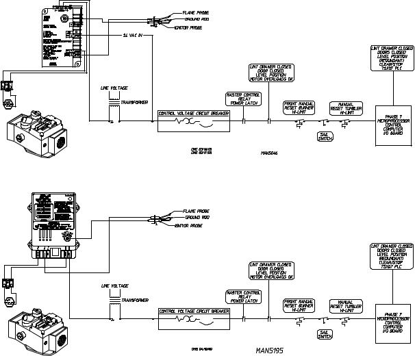
1.Gas dryers utilize a Direct Spark Ignition (DSI) module to monitor that a flame is established. If for some reason the flame signal is lost, the DSI module will shut off the gas valve and not retry ignition (no try to restart the flame). A spark of approximately 14,000 volts is used to establish a flame. The DSI module will turn the gas valve on and ignitor/flame-probe will spark for 8-seconds attempting a flame. Each time the dryer calls for heat the microprocessor controller (computer) will send a 24 VAC signal through the exhaust hi-limit, sail switch, and oven hi-limit. At that point, the DSI module will try for ignition.
DSI SYSTEM COMPONENTS/FUNCTIONS
Johnson (DSI) Control Module P/N 128935
ADC (DSI) Control Module P/N 128973
15
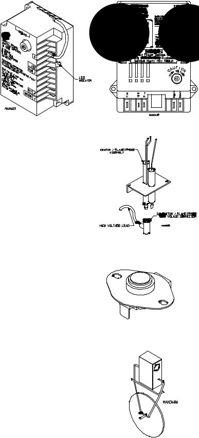
Johnson (DSI) Control Module
P/N 128935
a. The Direct Spark Ignition (DSI) Module is a 24 VAC
device designed to be the “controller” of the DSI system. When activated by the dryer controls, this module constantly monitors and controls the functions of the DSI system (i.e., spark activation, gas valve
off and on, flame verification, etc.). Additionally, the DSI
Module has self-diagnostic capabilities.
ADC (DSI) Control Module
P/N 128973
24 VAC Direct Spark Ignition (DSI) Module
b.The Ignitor/Flame-Probe Assembly is located in the burner flame area and is used to ignite the gas by use of a high voltage (HV) spark (approximately 14,000 volts) and to provide feedback information to the DSI Module as to whether the burner flame is evident (on).
c.The Manual Reset Burner Hi-Limit Switch is a thermostat type switch located in the burner. Its function is to discontinue heat (flame) in the event of an over temperature situation (above 330º F [166º C]). The hi-limit must be manually reset once the device tripped.
d.The Sail Switch Assembly is located on the Burner Assembly, downstream of the flame tubes. Its function is to detect whether or not there is sufficient airflow through the dryer.
Ignitor/Flame-ProbeAssembly
MAN3484
330º F (166º C) Thermostat
Sail Switch Assembly
16
e.The Manual Reset Basket (Tumbler) Hi-Limit Switch is a thermostat type switch located above the Lint Basket. Its function is to discontinue heat (flame) in the event of an over temperature situation (above 225º F [107º C]).
f.The gas valve used in the ADG-200 is of the redundant type which means that the gas valve is actually two (2) gas valves in one (1); one (1) in series with the other. This is a safety feature, which provides protection against gas flow in the event that one (1) of the valves does not seat properly. The valve also regulates the incoming gas pressure.
NOTE: THE DSI GAS VALVES ARE NOT FIELD REPAIRABLE.
MAN3484
225º F (107º C) Thermostat
Redundant Gas Valve
g.Normal Operation of the Direct Spark Ignition (DSI) System (refer to the illustration on page 15).
1)The DSI System consists of a microprocessor-based control module, along with an Ignitor/FlameProbe Assembly. This control utilizes a high voltage (HV) synchronous spark ignitor and a rectified flame sensor probe signal to locally control ALL basic functions in the gas burner.
On a call for heat by the dryers’ controls, 24 VAC is applied to the DSI module at which time the modules’ light emitting diode (L.E.D.) indicator will light “red” indicating that power has been established to the module. Almost immediately (up to approximately 1.5-seconds [prepurge]) the indicator will light “green,” the gas valve opens and the spark burst will be evident (on) for approximately 8-seconds. The burner flame should now be established/confirmed.
If at this time the flame has not been established and confirmed, the DSI module will “LOCKOUT” and the modules’ L.E.D. indicator will light “red” and stay on continuously. “Burner Ignition Control Fault” will display. To clear this fault press the “CLEAR/STOP” key.
Once the burner flame is established and confirmed, the DSI module indicator will light “green,” and the burner system will continue through a normal heating cycle, where the DSI system will cycle on and off as required by the dryer’s controls.
During the normal heating cycle, should a “FLAMEOUT” occur (i.e., severe air turbulence forces the flame away from the Ignitor/Flame-Probe Assembly), the DSI module will shut the gas valve off and immediately try to reestablish the burner flame. The DSI module will attempt to light the burner ONLY ONCE. If flame is not established, the DSI module will “LOCKOUT” and “Burner Ignition Control Fault” will display. To clear this fault press the “CLEAR/STOP” key.
17
h. Troubleshooting Flowchart - Quick Reference...
First Visual Check
No Spark And System Does Not Work
|
|
|
|
|
|
|
|
|
Is 24 VAC available |
|
|
|
|
|
|
|
|
|
|
|
|
|
|
|
|
||||||
|
|
|
|
|
|
|
|
|
at transformer? |
|
|
|
|
|
|
|
|
|
|
|
|
|
|
|
|
||||||
|
|
|
|
|
|
|
|
|
|
|
|
|
|
|
Is 24 VAC present from terminal |
||||||||||||||||
|
|
|
|
|
|
|
|
|
|
|
|
|
|
|
|
|
|
|
|
|
|
||||||||||
|
|
|
|
|
|
|
|
|
No |
|
|
Yes |
|
|
|
||||||||||||||||
|
|
|
|
|
|
|
|
|
|
|
|
|
|
|
|
|
|
|
THS2 to ground? |
||||||||||||
|
|
|
|
|
|
|
|
|
|
|
|
|
|
|
|
|
|
|
|
|
|
|
|
||||||||
|
|
|
|
|
|
|
|
|
|
|
|
|
|
|
|
|
|
|
|
|
|
|
No |
|
|
|
Yes |
||||
|
Is power available |
|
|
|
|
|
|
|
|
|
|
|
|
|
|
|
|||||||||||||||
|
|
to primary? |
|
|
|
|
|
|
|
|
|
|
|
|
|
|
|
|
|
|
|
|
|
|
|
|
|
|
|
||
|
No |
|
|
Yes |
|
|
|
Replace |
|
|
|
|
|
|
|
|
|
Are thermostat contacts and |
|
|
|||||||||||
|
|
|
|
|
Transformer. |
|
|
|
|
|
|
|
|
|
|
|
|||||||||||||||
|
|
|
|
|
|
|
|
|
|
|
|
|
|
|
|
|
limit control contacts closed? |
|
|
||||||||||||
|
|
|
|
|
|
|
|
|
|
|
|
Close |
|
|
|
|
|
|
|||||||||||||
|
|
|
|
|
|
|
|
|
|
|
|
|
|
|
|
|
|
|
|
|
|
|
|
|
|
|
|
||||
Determine why |
|
|
|
|
|
|
|
|
Contacts. |
|
|
|
|
|
No |
|
Yes |
|
|
||||||||||||
|
|
|
|
|
|
|
|
|
|
|
|
|
|
|
|
|
|
||||||||||||||
voltage is not |
|
|
|
|
|
|
|
|
|
|
|
|
|
|
|
|
|
|
|
|
|
|
|
|
|
|
|
|
|||
|
|
|
|
|
|
|
|
|
|
|
|
|
|
|
|
|
|
|
|
|
|
|
|
|
|
|
|||||
|
present. |
|
|
|
|
|
|
|
|
|
|
|
|
|
|
|
|
|
|
|
|
|
|
|
|
|
|
|
|
||
|
|
|
|
|
|
|
|
|
|
|
|
|
Check continuity of wiring to |
|
|
|
|
|
|
|
|||||||||||
|
|
|
|
|
|
|
|
|
|
|
|
|
|
|
|
|
|
|
|
||||||||||||
|
|
|
|
|
|
|
|
|
|
|
|
|
determine why voltage does |
|
|
|
|
|
|
|
|||||||||||
|
|
|
|
|
|
|
|
|
|
|
|
|
|
|
|
|
|
|
|
||||||||||||
|
|
|
|
|
|
|
|
|
|
|
|
|
|
not exist at THS2. |
|
|
|
|
|
|
|
||||||||||
|
|
|
|
|
|
|
|
|
|
|
|
|
|
|
|
|
|
|
|
|
|
|
|
|
|
|
|
|
|
||
|
|
|
|
|
|
|
|
|
|
|
|
|
|
|
|
|
|
|
|
|
|
|
|
|
|
|
|
|
|
|
|
|
|
|
|
|
|
|
|
|
|
|
|
|
|
|
|
|
|
|
|
|
|
|
|
Is jumper installed |
|||||||
|
|
|
|
|
|
|
|
|
|
|
|
|
|
|
|
|
|
|
|
|
|
|
|
|
from terminal 5 to |
||||||
|
|
|
|
|
|
|
|
|
|
|
|
|
|
|
|
|
|
|
|
|
|
|
|
|
|
|
ground? |
||||
|
|
|
|
|
|
|
|
|
|
|
|
|
|
Install |
|
|
|
|
|
|
|
||||||||||
|
|
|
|
|
|
|
|
|
|
|
|
|
|
|
|
|
|
|
|
|
|
|
|
|
|
|
|||||
|
|
|
|
|
|
|
|
|
|
|
|
|
|
|
|
|
|
No |
|
|
|
|
|
Yes |
|||||||
|
|
|
|
|
|
|
|
|
|
|
|
|
|
Jumper. |
|
|
|
|
|
|
|
|
|
|
|||||||
|
|
|
|
|
|
|
|
|
|
|
|
|
|
|
|
|
|
|
|
|
|
|
|
|
|
|
|||||
|
|
|
|
|
|
|
|
|
|
|
|
|
|
|
|
|
|
|
|
|
|
|
|
|
|
|
|
|
|
|
|
|
|
|
|
|
|
|
|
|
|
|
|
|
|
|
|
|
|
|
|
|
|
|
|
|
|
|
|
|
|
|
|
|
|
|
|
|
|
|
|
|
|
|
|
|
|
|
|
|
|
|
|
|
|
|
|
|
|
|
|
|
|
|
|
Open thermostat contacts for 30 seconds. Close contacts and wait for prepurge (if applicable)
period. Is spark present now?
|
|
|
|
|
|
|
|
|
|
|
|
No |
|
|
|
|
|
|
|
|
Yes |
|
|
||||
|
|
|
|
|
|
|
|
|
|
|
|
|
|
|
|
|
|
|
|
||||||||
|
|
|
|
|
|
|
|
|
|
|
|
|
|
|
|
|
|
|
|
|
|
|
|
|
|
|
|
|
|
|
|
|
|
|
|
|
|
|
|
|
|
|
|
|
|
|
|
|
|
|
|
|
|
|
|
|
Turn off supply voltage. |
|
|
|
|
|
|
|
|
|
|
|
|
|
|
|
|
|
|
|
|
||||||
|
Check high voltage cable. |
|
|
|
|
|
|
|
|
|
|
|
|
|
|
|
|
|
|
|
|
||||||
|
Is it securely attached to |
|
|
|
|
|
|
|
|
|
|
|
|
|
|
|
|
|
|
|
|
||||||
|
spark transformer? |
|
|
|
|
|
|
|
|
|
|
|
|
|
|
|
|
|
|
|
|
||||||
|
|
|
|
|
Is condition of high voltage |
|
|
|
|
||||||||||||||||||
|
|
|
|
|
|
|
|
|
|
|
|
|
|
|
|
||||||||||||
|
|
|
|
|
|
|
|
|
|
|
|
|
|
cable good (not brittle, |
|
|
|
|
|||||||||
|
No |
|
|
Yes |
|
|
|
|
|
|
|||||||||||||||||
|
|
|
|
|
|
|
|
|
|
|
|
||||||||||||||||
|
|
|
|
|
|
|
|
|
|
|
|
|
|
burnt, or cracked)? |
|
|
|
|
|||||||||
|
|
|
|
|
|
|
|
|
|
|
|
|
|
|
|
|
|||||||||||
|
|
|
|
|
|
|
|
|
|
|
|
|
|
|
|
|
|
|
|
|
|
|
|
|
|
|
|
|
Correct |
|
|
|
|
|
|
|
|
|
|
No |
|
|
Yes |
|
|
|
|
||||||||
|
|
|
|
|
|
|
|
|
|
|
|
|
|
|
|
|
|
|
|
|
|
|
|
|
|
|
|
|
|
|
|
|
|
|
|
|
|
|
|
|
|
|
|
|
|
|
|
|
|
|
|
|
|
|
|
|
|
|
|
|
|
|
|
|
|
|
|
Replace |
|
|
|
|
|
|
|
|
|
||||||
|
|
|
|
|
|
|
|
|
|
|
|
|
|
|
|
|
|
|
|
|
|
|
|
|
|||
|
|
|
|
|
|
|
|
|
|
|
|
|
|
|
|
|
|
|
|
|
|
|
|
|
|
|
|
|
|
|
|
|
|
|
|
|
|
|
|
|
|
|
|
|
Is spark electrode |
|
|
|
|||||||
|
|
|
|
|
|
|
|
|
|
|
|
|
|
|
|
|
|
ceramic cracked |
|
|
|
||||||
|
|
|
|
|
|
|
|
|
|
|
|
|
|
|
|
|
|
|
or is electrode |
|
|
|
|||||
|
|
|
|
|
Replace |
|
|
|
|
|
|
|
grounded out? |
|
|
|
|||||||||||
|
|
|
|
|
Johnson Control |
|
|
|
|
No |
|
|
Yes |
|
|
|
|||||||||||
|
|
|
|
|
|
|
|
|
|
|
|
|
|
||||||||||||||
|
|
|
|
|
module G760/761 |
|
|
|
|
|
|
|
|
|
|
|
|
|
|
|
|||||||
|
|
|
|
|
|
|
|
|
|
|
|
|
|
|
|
|
|
|
|
|
|
|
|
|
|
||
|
|
|
|
|
|
|
|
|
|
|
|
|
|
|
|
|
|
|
|
Replace electrode |
|
||||||
|
|
|
|
|
|
|
|
|
|
|
|
|
|
|
|
|
|
|
|
|
assembly. |
|
|||||
|
|
|
|
|
|
|
|
|
|
|
|
|
|
|
|
|
|
|
|
|
|
|
|
|
|
|
|
|
|
|
|
|
|
|
|
|
|
|
|
|
|
|
|
|
|
|
|
|
|
|
|
|
|
|
|
System was in lockout. Observe a complete operating cycle to determine why control locked out.
18
i. Troubleshooting Flowchart - Quick Reference...
Second Visual Check
Spark Present But Main Burner Does Not Come On
|
Is main valve wiring securely |
|
|
|
|
|
|
|
|
|
|
|
|
|
|
|||||
|
attached to terminal M.V.3 |
|
|
|
|
|
|
|
|
|
|
|
|
|
|
|||||
|
|
|
and ground? |
|
|
|
|
|
|
|
Is 24 VAC present |
|
|
|||||||
|
|
|
|
|
|
|
|
|
|
|
|
|
between terminals M.V.3 |
|
|
|||||
|
No |
|
|
|
Yes |
|
|
|
|
|||||||||||
|
|
|
|
|
|
|
|
|
|
|
|
and ground ? |
|
|
||||||
|
|
|
|
|
|
|
|
|
|
|
|
|
|
|
|
|
||||
|
|
|
|
|
|
|
|
|
|
|
|
|
|
|
|
|
|
|
|
|
|
Correct |
|
|
|
|
|
|
|
No |
|
Yes |
|
|
|||||||
|
|
|
|
|
|
|
|
|
|
|
|
|
|
|
||||||
|
|
|
|
|
|
|
|
|
|
|
|
|
|
|
|
|
|
|
|
|
|
|
|
|
|
|
|
|
|
|
|
|
|
|
|
|
|
|
|
||
|
|
|
|
|
|
Replace |
|
|
|
|
|
|
|
|
|
|
|
|
|
|
|
|
|
|
Johnson Control |
|
|
|
|
|
|
|
|
|
|
|
|
|
|||
|
|
|
|
|
|
|
|
|
|
|
|
|
|
|
|
|
||||
|
|
|
|
module G760/761 |
|
|
|
|
|
|
|
|
|
|
|
|
|
|||
|
|
|
|
|
|
|
|
|
|
|
|
|
|
|
|
|
||||
|
|
|
|
|
|
|
|
|
|
|
|
|
|
|
Check for continuity in |
|||||
|
|
|
|
|
|
|
|
|
|
|
|
|
|
|
wiring from M.V.3 to gas |
|||||
|
|
|
|
|
|
Determine |
|
|
|
|
valve, and gas valve to GR. |
|||||||||
|
|
|
|
|
|
why continuity |
|
|
|
|
No |
|
Yes |
|||||||
|
|
|
|
|
|
|
|
|
|
|
||||||||||
|
|
|
|
|
|
does not exist. |
|
|
|
|
|
|
|
|
|
|
||||
|
|
|
|
|
|
|
|
|
|
|
|
|
|
|
|
|
|
|
|
|
Is inlet gas pressure per manufacturer's specifications?
Correct |
|
|
|
|
|
|
|
|
|
No |
Yes |
||
|
|
|
||||
|
|
|
|
|
|
|
Is Spark gap .125 in. and in gas stream?
Correct |
|
|
|
|
|
|
|
|
|
No |
Yes |
||
|
|
|
||||
|
|
|
|
|
|
|
Replace gas valve.
19

j. Troubleshooting Flowchart - Quick Reference...
Third Visual Check
Main Burner Lights But Will Not Stay On
|
Is flame sensor cable |
|
|
|
|
|
|
|
|
|
|
|
|
|
|
|
|
|
|
|
|
|
|
|
|
|
|
|
||||||||||
|
securely attached |
|
|
|
|
|
|
|
|
|
|
|
|
|
|
|
|
|
|
|
|
|
|
|
|
|
|
|
||||||||||
|
|
|
to terminal 4? |
|
|
|
|
|
|
|
|
Does continuity exist |
|
|
|
|
|
|
|
|
||||||||||||||||||
|
|
|
|
|
|
|
|
|
|
|
|
|
|
|
|
|
|
|
|
|
|
|
|
from control |
|
|
|
|
|
|
|
|
||||||
|
No |
|
|
|
|
|
|
Yes |
|
|
|
|
|
|
|
|
|
|
|
|
|
|
|
|
|
|
|
|||||||||||
|
|
|
|
|
|
|
|
|
|
|
|
|
|
|
|
|
to flame sensor? |
|
|
|
|
|
|
|
|
|||||||||||||
|
|
|
|
|
|
|
|
|
|
|
|
|
|
|
|
|
|
|
|
|
|
|
|
|
|
|
|
|
|
|||||||||
|
|
|
|
|
|
|
|
|
|
|
|
|
|
|
|
|
|
|
|
|
|
|
|
|
|
|
|
|
|
|
|
|
|
|
|
|
|
|
|
Correct |
|
|
|
|
|
|
|
|
|
|
|
|
No |
|
|
|
|
|
Yes |
|
|
|
|
|
|
|
|
||||||||||
|
|
|
|
|
|
|
|
|
|
|
|
|
|
|
|
|
|
|
|
|
|
|
|
|
|
|
|
|
|
|
|
|
|
|
|
|
|
|
|
|
|
|
|
|
|
|
|
|
|
|
|
|
|
|
|
|
|
|
|
|
|
|
|
|
|
|
|
|
|
|
|
|
|
|
|
|
|
|
|
|
|
|
|
|
|
Replace |
|
|
|
|
|
|
|
|
|
|
|
|
|
|
|
|
|
|
|
|
|
|
|
|
|
|
|
|||
|
|
|
|
|
|
|
|
sensor |
|
|
|
|
|
|
|
|
|
|
|
|
|
|
|
|
|
|
|
|
|
|
|
|
|
|
|
|||
|
|
|
|
|
|
|
|
|
|
|
|
|
|
|
|
|
|
|
|
|
|
|
|
|
|
|
|
|
|
|
|
|
|
|
||||
|
|
|
|
|
|
|
|
cable. |
|
|
|
|
|
|
|
|
|
|
|
|
|
|
|
|
|
|
|
|
|
|
|
|
|
|
|
|||
|
|
|
|
|
|
|
|
|
|
|
|
|
|
|
|
|
|
|
|
|
|
|
|
|
|
|
|
|
|
|
|
|
|
|
||||
|
|
|
|
|
|
|
|
|
|
|
|
|
|
|
|
|
|
|
|
|
|
|
|
|
Is flame sensor corroded |
|
|
|
|
|||||||||
|
|
|
|
|
|
|
|
|
|
|
|
|
|
|
|
|
|
|
|
|
|
|
|
|
|
or is ceramic cracked? |
|
|
|
|
||||||||
|
|
|
|
|
|
|
|
|
Correct or |
|
|
|
|
|
|
|
|
|
|
|
|
|||||||||||||||||
|
|
|
|
|
|
|
|
|
|
|
|
|
|
|
|
|
|
|
|
|
|
|
|
|
|
|
|
|
||||||||||
|
|
|
|
|
|
|
|
|
replace |
|
|
|
|
|
|
|
|
|
|
|
|
|
|
No |
|
|
Yes |
|
|
|
|
|||||||
|
|
|
|
|
|
|
|
|
|
|
|
|
|
|
|
|
|
|
|
|
|
|
|
|
|
|
|
|
||||||||||
|
|
|
|
|
|
|
|
|
sensor. |
|
|
|
|
|
|
|
|
|
|
|
|
|
|
|
|
|
|
|
|
|
|
|
|
|
|
|
||
|
|
|
|
|
|
|
|
|
|
|
|
|
|
|
|
|
|
|
|
|
|
|
|
|
|
|
|
|
|
|
|
|
|
|||||
|
|
|
|
|
|
|
|
|
|
|
|
|
|
|
|
|
|
|
|
|
|
|
|
|
|
|
|
|
|
|
|
|
|
|
|
|
|
|
|
|
|
|
|
|
|
|
|
|
|
|
|
|
|
|
|
|
|
|
|
|
|
|
|
|
|
|
|
|
|
|
|
|
|
|
|
|
|
|
|
|
|
|
|
|
|
|
|
|
|
|
|
|
|
|
|
|
|
|
|
|
|
|
|
|
Does continuity exist in |
|
|
|||||||||
|
|
|
|
|
|
|
|
|
|
|
|
|
|
|
|
|
|
|
|
|
|
|
|
|
|
|
ground path from burner |
|
|
|||||||||
|
|
|
|
|
|
|
|
|
|
|
|
|
|
|
|
|
|
|
|
|
|
|
|
|
|
|
|
|
to control? |
|
|
|||||||
|
|
|
|
|
|
|
|
|
Correct |
|
|
|
|
|
|
|
|
|
|
|
|
|
|
|
|
|
|
|
||||||||||
|
|
|
|
|
|
|
|
|
|
|
|
No |
|
|
|
Yes |
|
|
||||||||||||||||||||
|
|
|
|
|
|
|
|
|
|
|
|
|
|
|
|
|
|
|
|
|
|
|||||||||||||||||
|
|
|
|
|
|
|
|
|
|
|
|
|
|
|
|
|
|
|
|
|
|
|
|
|
|
|
|
|
|
|
|
|
|
|
||||
|
|
|
|
|
|
|
|
|
|
|
|
|
|
|
|
|
|
|
|
|
|
|
|
|
|
|
|
|
|
|
|
|
|
|
|
|
|
|
|
|
|
|
|
|
|
|
|
|
|
|
|
|
|
|
|
|
|
|
|
|
|
|
|
|
|
|
|
Check flame sensing current |
|
||||||||
|
|
|
|
|
|
|
|
|
Is flame sensor |
|
|
|
|
|
|
during trial. Is current |
|
|||||||||||||||||||||
|
|
|
|
|
|
|
|
|
|
|
|
|
|
|
greater than 0.3μ A DC? |
|
||||||||||||||||||||||
|
|
|
|
|
|
|
|
|
positioned per |
|
|
|
|
|
|
|
||||||||||||||||||||||
|
|
|
|
|
|
|
|
|
|
|
|
|
|
|
|
|
|
|
|
|
|
|
|
|
||||||||||||||
|
|
|
|
|
|
|
manufacturer's specifications? |
|
|
|
|
|
|
No |
|
|
|
|
Yes |
|
||||||||||||||||||
|
|
|
|
|
|
|
|
|
|
|
|
|
|
|
|
|
|
|||||||||||||||||||||
|
|
|
|
|
|
|
|
|
|
|
|
|
|
|
|
|
|
|
|
|
|
|
|
|
|
|
|
|
|
|
|
|
|
|
|
|
|
|
|
|
|
|
|
|
|
|
No |
|
|
|
|
|
Yes |
|
|
|
|
|
|
|
|
|
|
|
|
|
|
|
|
||||||||
|
|
|
|
|
|
|
|
|
|
|
|
|
|
|
|
|
|
|
|
|
|
|
|
|
|
|
|
|
|
|
|
|
|
|
|
|
|
|
|
|
|
|
|
|
|
|
|
|
|
|
|
|
|
|
|
|
|
|
|
|
|
|
|
|
|
|
|
|
|
|
|
|
|
|
|
|
|
|
|
|
|
|
|
|
|
Correct |
|
|
|
|
|
|
|
|
|
|
|
|
|
|
|
|
|
|
|
|
|
|
|
|
|
|
|
|||
|
|
|
|
|
|
|
|
|
|
|
|
|
|
|
|
|
|
|
|
|
|
|
|
|
|
|
|
|
|
|
|
|
|
|
||||
|
|
|
|
|
|
|
|
|
|
|
|
|
|
|
|
|
|
|
|
|
|
|
|
|
|
|
|
|
|
|
|
|
|
|
Replace |
|
||
|
|
|
|
|
|
|
|
|
|
|
|
|
|
|
|
|
|
|
|
|
|
|
|
|
|
|
|
|
|
|
|
|
|
|
|
|||
|
|
|
|
|
|
|
|
|
|
|
|
|
|
|
|
|
|
|
|
|
|
|
|
|
|
|
|
|
|
|
|
|
|
Johnson Control |
|
|||
|
|
|
|
|
|
|
|
|
|
|
|
|
Replace |
|
|
|
|
|
|
|
|
|
|
|
|
|||||||||||||
|
|
|
|
|
|
|
|
|
|
|
|
|
|
|
|
|
|
|
|
|
|
|
|
|
module |
|
||||||||||||
|
|
|
|
|
|
|
|
|
|
|
|
Johnson Control |
|
|
|
|
|
|
|
|
|
|
|
|
|
|||||||||||||
|
|
|
|
|
|
|
|
|
|
|
|
|
|
|
|
|
|
|
|
|
|
|
|
G760/761 |
|
|||||||||||||
|
|
|
|
|
|
|
|
|
|
|
|
|
|
module |
|
|
|
|
|
|
|
|
|
|
|
|
|
|||||||||||
|
|
|
|
|
|
|
|
|
|
|
|
|
|
|
|
|
|
|
|
|
|
|
|
|
|
|
|
|
|
|||||||||
|
|
|
|
|
|
|
|
|
|
|
|
|
G760/761 |
|
|
|
|
|
|
|
|
|
|
|
|
|
|
|
|
|||||||||
|
|
|
|
|
|
|
|
|
|
|
|
|
|
|
|
|
|
|
|
|
|
|
|
|
|
|
|
|
|
|
|
|
|
|
|
|
|
|
20
B. TROUBLESHOOTING THE DIRECT SPARK IGNITION (DSI) SYSTEM
NOTE: The troubleshooting information provided in this manual is intended for use by qualified service technicians only. OBSERVE ALL SAFETY PRECAUTIONS displayed on the equipment or specified in the AD-200 Phase 7 Non-Tilting Installation/Operator’s Manual (ADC Part No. 112142) included with the dryer.
IMPORTANT: UNDER NO CIRCUMSTANCES SHOULD ANY SAFETY OR HEAT CIRCUIT DEVICES EVER BE DISABLED.
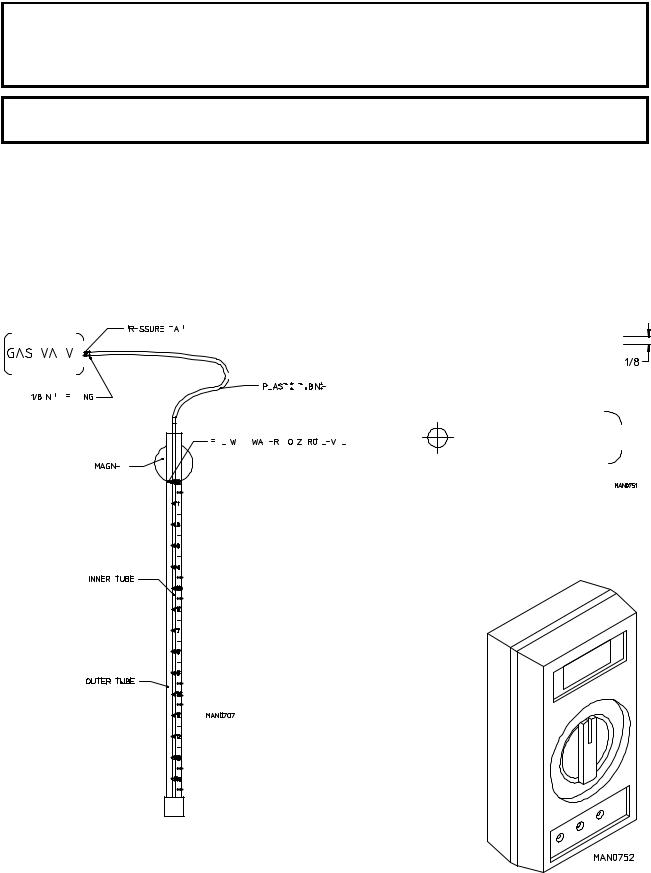
THE FOLLOWING PIECES OF TEST EQUIPMENT WILL BE REQUIRED TO TROUBLESHOOT THIS SYSTEM WITH MINIMAL TIME AND EFFORT
|
|
|
|
|
|
|
|
|
|
|
|
|
|
|
|
|
|
|
|
|
|
|
MANOMETER |
|
|
|
|
|
|
|
|
|
|
|
|
|
|
|
|
|
|
|
|
|
|
|
|
|
|
DSI IGNITOR GAP FEELER GAUGE |
||||||||||||||||||||||||||||||||
|
|
|
|
|
|
|
|
|
|
|
|
|
|
|
|
|
|
|
|
|
|
|
|
|
|
|
|
|
|
|
|
|
|
|
|
|
|
|
|
|
|
|
|
|
|
|
|
|
(1/8” [3.175 mm]) |
|||||||||||||||||||||||||||||||||
|
|
|
|
|
|
|
|
|
|
|
|
|
Used To Measure Gas Pressure In Inches |
|
|
|
|
|
|
|
|
|
|
|
|
|
|
|
|
|
|
|
|
|
|
|
|
|
|
|||||||||||||||||||||||||||||||||||||||||||
|
|
|
|
|
|
|
|
|
|
|
|
|
|
|
|
|
|
|
|
|
|
|
|
|
|
|
|
|
|
|
|
|
|
|
|
|
|
|
Used For Checking Gap Between Ignitor/ |
|||||||||||||||||||||||||||||||||||||||||||
|
|
|
|
|
|
|
|
|
|
|
|
|
|
|
|
|
Of Water Column (W.C.) |
|
|
|
|
|
|
|
|
|
|
|
|
|
|
|
|
|
|
|
|
|
|
|
|
|
|
|||||||||||||||||||||||||||||||||||||||
|
|
|
|
|
|
|
|
|
|
|
|
|
|
|
|
|
|
|
|
|
|
|
|
|
|
|
|
|
|
|
|
|
|
|
|
|
|
|
|
|
|
Flame-Probe Assembly and Spark Electrode |
||||||||||||||||||||||||||||||||||||||||
|
|
|
|
|
|
|
|
|
|
|
|
|
|
|
|
|
|
|
|
|
|
|
|
|
|
|
|
|
|
|
|
|
|
|
|
|
|
|
|
|
|
|
|
|
|
|
|
|
|
|
|
|
|
|
|
|
|
|
|
|
|
|
|
|
|
|
|
|
|
|
|
|
|
|
|
|
|
|
||||
|
|
|
|
|
|
|
|
|
|
|
|
|
|
|
|
|
|
|
|
|
|
|
|
|
|
|
|
|
|
|
|
|
|
|
|
|
|
|
|
|
|
|
|
|
|
|
|
|
|
|
|
|
|
|
|
|
|
|
|
|
|
|
|
|
|
|
|
|
|
|
|
|
|
|
|
|
|
|
|
|
|
|
|
|
|
|
|
|
|
|
|
|
|
|
|
|
|
|
|
|
|
|
|
|
|
|
|
|
|
|
|
|
|
|
|
|
|
|
|
|
|
|
|
|
|
|
|
|
|
|
|
|
|
|
|
|
|
|
|
|
|
|
|
|
|
|
|
|
|
|
|
|
|
|
|
|
|
|
|
|
|
|
|
|
|
|
|
|
|
|
|
|
|
|
|
|
|
|
|
|
|
|
|
|
|
|
|
|
|
|
|
|
|
|
|
|
|
|
|
|
|
|
|
|
|
|
|
|
|
|
|
|
|
|
|
|
|
|
|
|
|
|
|
|
|
|
|
|
|
|
|
|
|
|
|
|
|
|
|
|
|
|
|
|
|
|
|
|
|
|
|
|
|
|
|
|
|
|
|
|
|
|
|
|
|
|
|
|
|
|
|
|
|
|
|
|
|
|
|
|
|
|
|
|
|
|
|
|
|
|
|
|
|
|
|
|
|
|
|
|
|
|
|
|
|
|
|
|
|
|
|
|
|
|
|
|
|
|
|
|
|
|
|
|
|
|
|
|
|
|
|
|
|
|
|
|
|
|
|
|
|
|
|
|
|
|
|
|
|
|
|
|
|
|
|
|
|
|
|
|
|
|
|
|
|
|
|
|
|
|
|
|
|
|
|
|
|
|
|
|
|
|
|
|
|
|
|
|
|
|
|
|
|
|
|
|
|
|
|
|
|
|
|
|
|
|
|
|
|
|
|
|
|
|
|
|
|
|
|
|
|
|
|
|
|
|
|
|
|
|
|
|
|
|
|
|
|
|
|
|
|
|
|
|
|
|
|
|
|
|
|
|
|
|
|
|
|
|
|
|
|
|
|
|
|
|
|
|
|
|
|
|
|
|
|
|
|
|
|
|
|
|
|
|
|
|
|
|
|
|
|
|
|
|
|
|
|
|
|
|
|
|
|
|
|
|
|
|
|
|
|
|
|
|
|
|
|
|
|
|
|
|
|
|
|
|
|
|
|
|
|
|
|
|
|
|
|
|
|
|
|
|
|
|
|
|
|
|
|
|
|
|
|
|
|
|
|
|
|
|
|
|
|
|
|
|
|
|
|
|
|
|
|
|
|
|
|
|
|
|
|
|
|
|
|
|
|
|
|
|
|
|
|
|
|
|
|
|
|
|
|
|
|
|
|
|
|
|
|
|
|
|
|
|
|
|
|
|
|
|
|
|
|
|
|
|
|
|
|
|
|
|
|
|
|
|
|
|
|
|
|
|
|
|
|
|
|
|
|
|
|
|
|
|
|
|
|
|
|
|
|
|
|
|
|
|
|
|
|
|
|
|
|
|
|
|
|
|
|
|
|
|
|
|
|
|
|
|
|
|
|
|
|
|
|
|
|
|
|
|
|
|
|
|
|
|
|
|
|
|
|
|
|
|
|
|
|
|
|
|
|
|
|
|
|
|
|
|
|
|
|
|
|
|
|
|
|
|
|
|
|
|
|
|
|
|
|
|
|
|
|
|
|
|
|
|
|
|
|
|
|
|
|
|
|
|
|
|
|
|
|
|
|
|
|
|
|
|
|
|
|
|
|
|
|
|
|
|
|
|
|
|
|
|
|
|
|
|
|
|
|
|
|
|
|
|
|
|
|
|
|
|
|
|
|
|
|
|
|
|
|
|
|
|
|
|
|
|
|
|
|
|
|
|
|
|
|
|
|
|
|
|
|
|
|
|
|
|
|
|
|
|
|
|
|
|
|
|
|
|
|
|
|
|
|
|
|
|
|
|
|
|
|
|
|
|
|
|
|
|
|
|
|
|
|
|
|
|
|
|
|
|
|
|
|
|
|
|
|
|
|
|
|
|
|
|
|
|
|
|
|
|
Available From ADC
MULTIMETER/VOLTMETER
For Measuring Voltage
Available From ADC
21
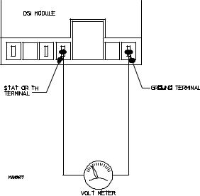
1.Direct Spark Ignition (DSI) Troubleshooting Terms (definitions) ADC (DSI) Control Module P/N 128973 a. DSI MODULE “RED” L.E.D. INDICATOR LIGHT - This “red” light emitting diode (L.E.D.) light is
located in the upper right corner of the DSI module (refer to the top illustration on page 16). This is a diagnostic indicator that simplifies the operational and troubleshooting procedures of the DSI system.
b. LOCKOUT MODE - DSI module “red” L.E.D. indicator light stays on continuously. This indicates there is a system fault and most likely, the fault is the DSI module itself.
c. FLAMEOUT - Burner flame shutdown by the DSI module due to lack of flame verification. This condition occurs only after ignition is evident but is lost. The DSI system will immediately attempt to relight the burner.
d.RECYCLE - Flame has been sensed but lost. Initiate a new sequence (THERE ARE NO RETRIES).
2.Troubleshooting and System Basic Diagnosis ADC (DSI) Control Module P/N 128973 a. Preliminary Steps
The following steps must be performed to minimize the time required to isolate cause of fault.
1) DSI module L.E.D. indicator light is off (no “red” or “green” light).
a) Check for voltage (approximately 24 VAC) across the DSI model terminals “TH” and “GND”...
If voltage (approximately 24 VAC) is evident, then, there is a malfunction within the DSI module itself, and it must be replaced.
If there is no voltage present, then problem is not the DSI module or the ignition system, the problem is elsewhere in the dryer (i.e., dryer’s heat circuit [sail switch, hi-limit circuits, etc.]).
2)DSI module L.E.D. indicator lights “red” for approximately 1.5-seconds (prepurge). This indicates that ALL the controls (including ALL the safety circuits) are functioning and power is being supplied to the DSI module.
3)DSI module L.E.D. indicator lights “green.” This indicates a normal heating cycle. This also indicates that the preliminary diagnostics of the module has confirmed that the DSI module is functional.
4)DSI module L.E.D. indicator lights “red” continuously...“LOCKOUT” mode. This indicates that there is a system fault and most likely the fault is internal to the DSI module. To make sure, open and close the main door. Restart the dryer...if the module LOCKS OUT (“red” L.E.D. indicator light stays on continuously) again, replace the DSI module.
22

If the dryer repeatedly has Direct Spark Ignition (DSI) module “LOCKOUT” failures, the cause may be due to high voltage (HV) not getting into the DSI module ignitor probe assembly.
5)Check to insure that the red high voltage wire (between the ignitor spark electrode and the DSI module) is not wrapped around the sensor probe wire (the wire between the DSI module FP terminal and the Ignitor/Flame-Probe Assembly). If the wires are touching one another, separate and secure in place AWAY FROM ONE ANOTHER.
6)Check to insure that the dryer is properly grounded and that the ground connections (GND) to the DSI module are secure.
7)If the problem persists, it is most likely to be in the external components (not the DSI module), or wiring, due to a “FLAMEOUT”...proceed as follows:
NOTE: Preliminary steps - DO NOT omit - to minimize the time required to troubleshoot this system.
a)Disconnect the electrical power to the dryer.
b)Visually, check the DSI module components for visual damage.
c)Check wiring for loose connections, nicks, cracking at the ceramic insulator, or shorting of the sensor to the burner.
d)Inspect the DSI Ignitor/Flame-Probe Assembly...
...Check electrode for visible cracking at the ceramic insulator or shorting of sensor to burner
...Check to insure that the flame sensor rod is positioned over the flame area
...Check for carbon deposits on the flame sensor rod
...Check to insure that there is a 1/8” +/- 1/32” (3.175 mm +/- 0.79248 mm) gap between the ground rod and the ignitor spark electrode
b.After performing these inspections and making corrections - if any - restore power to the dryer...start the dryer and operate through one (1) complete cycle to insure that ALL components are functioning properly. If a no heat condition persists, refer to the Troubleshooting Flowcharts on page 25, page 26, and page 27.
1)To effectively use this information or the flowcharts, each step must be completed in sequence, performing whatever tests are suggested. After the completion of each test, the guide will direct the Service Technician to the next logical step in the troubleshoot sequence based on the outcome of the previous check.
2)Components should be replaced only after each step has been completed and replacements after each step has been completed and replacement is suggested in the flowchart. However, the experienced technician realizes that a loose connection or broken or shorted wire may be at fault where electrical components are concerned...and not necessarily the suspected component itself.
23
c.Three (3) Visual Checks
1)Does the Direct Spark Ignition (DSI) Ignitor/Flame-Probe Assembly start sparking? If not, refer to the FIRST VISUAL CHECK on page 25.
2)Does the main burner ignite?
If not, refer to the SECOND VISUAL CHECK on page 26.
3)Does the main burner remain lit after ignition has been established (“FLAMEOUT”)? If not, refer to the THIRD VISUAL CHECK on page 27.
24
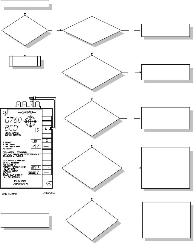
d. Troubleshooting Flowchart - Quick Reference...
Computer/Timer Calls For Heat
Is spark evident (on)
No
at Ignitor Assembly?
Yes
Go To Chart 2
Replace the DSI Module.
Energize system and check  Yes for proper operation.
First Visual Check
(Does Ignitor Spark?)
Is 24 Volts present across DSI Module
terminals TH and COM?
Yes
Check
High Voltage (HV) Lead for nicks or cracking, where sparking to ground may occur. Is this wire
damaged?
No
Visually inspect Spark Electrode Assembly. Is
ceramic cracked or Spark Electrode incorrectly gapped?
No
Visually inspect High Voltage (HV) Wire
connections at both DSI Module and Ignitor Assembly.
Are connections secure?
Yes
Remove
High Voltage (HV) Wire from
DSI Module and visually inspect. Is conductor visible at end of
HV Wire?
No
Yes
Yes
No
No
Open circuit to DSI System.  Check the 24 VAC power source Sail Switch and Hi-Limit.
Repair or replace HV Lead Assembly.
Energize system and check for proper operation.
If cracked, replace Electrode Assembly. Correct gap size
 is 1/8" (+/- 1/32").
Energize system and check for proper operation.
1.At DSI Ignitor Assembly be sure HV Wire is secure in the boot as well as the connection to the Ignitor Probe Assembly.
2.At DSI Module, center the end of the HV Wire with a Spike Terminal. Energize system and check for proper operation.
Cut the end off of the HV Wire 1/4" at a time until conductor becomes visible and is flush with the insulation.
 Reconnect the HV Wire to the Spike Terminal on the DSI Module.
Energize system and check for proper operation.
25
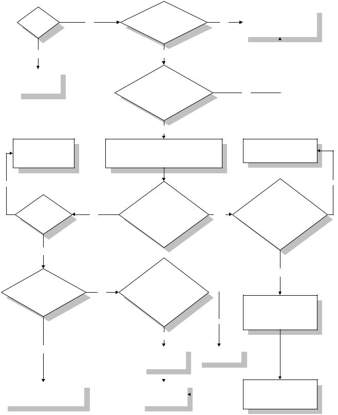
e. Troubleshooting Flowchart - Quick Reference...
Second Visual Check
(Does Main Burner Ignite?)
|
|
Does |
|
Is manual |
|
|
|
Turn knob to “ON/OPEN” |
|||
|
|
|
knob on the Gas Valve |
|
|
|
position. |
||||
|
main burner |
|
No |
|
No |
|
|||||
|
|
in the “ON” |
|
|
Energize system and |
||||||
|
|
light? |
|
|
|
|
|||||
|
|
|
position? |
|
|
|
check for proper operation. |
||||
|
|
|
|
|
|
|
|
|
|||
|
|
Yes |
|
Yes |
|
|
|
|
|
||
|
|
|
|
|
|
|
|
||||
|
|
|
|
|
|
|
|
||||
|
|
|
|
|
|
|
|
|
|
|
|
|
|
Go To |
|
|
|
Is |
|
|
|
|
|
|
|
|
|
|
|
|
|
||||
|
|
Third Visual |
|
|
|
dryer Internal Gas |
|
|
|
|
|
|
|
Check |
|
|
|
Shut-Off Valve and |
|
|
|
No |
|
|
|
|
|
|
|
ALL External Gas Shut-Off |
|
|
|
|
|
|
|
|
|
|
|
Valves in the open |
|
|
|
|
|
|
|
|
|
|
|
position? |
|
|
|
|
|
|
|
|
|
|
|
Yes |
|
|
|
|
|
Restore gas supply. |
|
Turn manual knob on the Gas Valve to the |
|
|
Energize system and |
|
“OFF” position. |
|
|
check for proper |
|
Connect a manometer to the Gas Valve |
|
|
operation. |
|
outlet pressure tap. |
|
|
No |
|
|
|
|
|
|
Turn |
|
|
Is |
|
manual knob on |
|
|
|
the Gas Valve to the |
|
||
gas available |
|
|
||
No |
“ON” position. |
Yes |
||
at the |
||||
|
Energize the system. |
|
||
source? |
|
|
||
|
Is outlet pressure |
|
||
|
|
|
||
|
|
detected? |
|
Correct supply pressure. Energize system and check for proper operation.
No
Is outlet
Water Column (W.C.) pressure correct?
Natural 3.5” - 4.0” W.C. (8.7 mb - 9.9 mb)
L.P. 10.5” - 11.0” W.C. (26.1 mb - 27.4 mb)
Yes
Energize |
|
|
|
|
With |
|
|
|
||||
|
|
|
|
system energized, |
|
|
|
|||||
system. Is 24 VAC |
|
|
|
|
|
|
|
|||||
|
|
|
|
is 24 VAC present |
|
|
|
|||||
present across leads |
|
No |
|
|
|
|
|
|||||
|
across the “MV” and “GND” |
|
|
|
||||||||
at the Gas |
|
|
|
|
|
|||||||
|
|
|
|
terminals of the DSI |
|
|
|
|||||
Valve? |
|
|
|
|
|
|
|
|||||
|
|
|
|
Module? |
|
|
|
|||||
|
|
|
|
|
|
|
|
|||||
|
|
|
|
|
|
|
|
|
|
|
No |
|
|
|
|
|
|
Yes |
|
|
|
||||
Yes |
|
|
|
|
|
|
|
|
|
|
|
|
|
|
|
|
Replace High |
|
|
|
|
Replace |
|||
|
|
|
|
|
|
|
|
|
||||
|
|
|
|
|
Voltage (HV) |
|
|
|
DSI Module |
|||
|
|
|
|
|
leads |
|
|
|
|
|
|
|
|
|
|
|
|
|
|
|
|
|
|
||
|
|
|
|
|
|
|
|
|
|
|
|
|
|
|
|
|
|
|
|
|
|
|
|
|
|
|
|
|
|
|
|
|
|
|
|
|
|
|
Replace the Gas Valve. |
|
|
|
|
Energize system |
|
|
|
|
|
||
Energize the system and |
|
|
|
|
and check for |
|
|
|
|
|
||
|
|
|
|
|
|
|
|
|
||||
check for proper operation. |
|
|
|
|
proper operation. |
|
|
|
|
|
||
|
|
|
|
|
|
|
|
|
|
|
|
|
Yes
Check Spark Electrode for proper gap and insure that the spark is in the path of the gas flow...
Refer To Service Section.
Make the necessary corrections. Energize system and
check for proper operation.
26
 Loading...