


 Loading...
Intel Pentium 4 System Board
Socket 775
User’s Manual
For more information:
www.abit.com.tw
4200-0433-01 Rev. 1.00

Copyright and Warranty Notice
The information in this document is subject to change without notice and does not represent a commitment on part of the vendor, who assumes no liability or responsibility for any errors that may appear in this manual.
No warranty or representation, either expressed or implied, is made with respect to the quality, accuracy or fitness for any particular part of this document. In no event shall the manufacturer be liable for direct, indirect, special, incidental or consequential damages arising from any defect or error in this manual or product.
Product names appearing in this manual are for identification purpose only and trademarks and product names or brand names appearing in this document are the property of their respective owners.
This document contains materials protected under International Copyright Laws. All rights reserved. No part of this manual may be reproduced, transmitted or transcribed without the expressed written permission of the manufacturer and authors of this manual.
If you do not properly set the motherboard settings, causing the motherboard to malfunction or fail, we cannot guarantee any responsibility.
The Fatal1ty name, Fatal1ty logos and the Fatal1ty likeness are trademarks of Fatal1ty, Inc. All rights reserved. Built to Kill is a trademark of PWX, LLC.
© 2004 ABIT Computer Corporation.
All other trademarks are the property of their respective owners.
Fatal1ty AA8XE

Table of Contents
Chapter 1. Introduction .......................................................................... |
1-1 |
|
1-1. |
Fatal1ty..................................................................................................... |
1-1 |
1-2. |
Features & Specifications ........................................................................ |
1-3 |
1-3. |
Layout Diagram ....................................................................................... |
1-5 |
Chapter 2. Hardware Setup.................................................................... |
2-1 |
||
2-1. |
Install The Motherboard........................................................................... |
2-1 |
|
2-2. Install CPU, Heatsink and Fan Assembly................................................ |
2-3 |
||
2-3. |
Install System Memory ............................................................................ |
2-5 |
|
2-4. Connectors, Headers and Switches .......................................................... |
2-7 |
||
|
(1). |
ATX Power Input Connectors........................................................ |
2-7 |
|
(2). |
FAN Power Connectors ................................................................. |
2-8 |
|
(3). |
CMOS Memory Clearing Header .................................................. |
2-9 |
|
(4). |
Wake-up Header........................................................................... |
2-10 |
|
(5). |
Front Panel Audio Connection Header ........................................ |
2-11 |
|
(6). |
Back Panel Audio Connection Slot.............................................. |
2-12 |
|
(7). |
Front Panel COM1 Connection Header....................................... |
2-14 |
|
(8). |
Front Panel Switches & Indicators Headers ................................ |
2-15 |
|
(9). |
Additional IEEE1394 Port Headers ............................................. |
2-16 |
|
(10). |
Additional USB Port Headers...................................................... |
2-17 |
|
(11). |
GURU Clock Connection Header................................................ |
2-18 |
|
(12). |
Internal Audio Connectors ........................................................... |
2-18 |
|
(13). |
Floppy and IDE Disk Drive Connectors...................................... |
2-19 |
|
(14). |
POST Code Display ..................................................................... |
2-20 |
|
(15). |
Serial ATA Connectors ................................................................. |
2-21 |
|
(16). |
PCI Express x16 Slot ................................................................... |
2-22 |
|
(17). |
PCI Express x1 Slots.................................................................... |
2-22 |
|
(18). |
Onboard Switches ........................................................................ |
2-23 |
|
(19). |
Status Indicator ............................................................................ |
2-24 |
|
(20). |
Back Panel Connectors ................................................................ |
2-25 |
Chapter 3. BIOS Setup............................................................................ |
3-1 |
|
3-1. |
µGuru™ Utility ......................................................................................... |
3-2 |
3-2. |
Standard CMOS Features......................................................................... |
3-9 |
3-3. |
Advanced BIOS Features....................................................................... |
3-12 |
3-4. |
Advanced Chipset Features.................................................................... |
3-15 |
3-5. |
Integrated Peripherals ............................................................................ |
3-17 |
3-6. |
Power Management Setup ..................................................................... |
3-22 |
User’s Manual

3-7. |
PnP/PCI Configurations......................................................................... |
3-25 |
3-8. |
Load Fail-Safe Defaults ......................................................................... |
3-26 |
3-9. |
Load Optimized Defaults ....................................................................... |
3-26 |
3-10. |
Set Password .......................................................................................... |
3-26 |
3-11. |
Save & Exit Setup .................................................................................. |
3-26 |
3-12. |
Exit Without Saving............................................................................... |
3-26 |
Appendix A. |
Install Intel Chipset Software Utility............................................... |
A-1 |
Appendix B. |
Install Intel Application Accelerator RAID.................................... |
B-1 |
Appendix C. |
Install Audio Driver ......................................................................... |
C-1 |
Appendix D. |
Install LAN Driver ........................................................................... |
D-1 |
Appendix E. |
Install USB 2.0 Driver ..................................................................... |
E-1 |
Appendix F. |
Install ABIT µGuru Utility .............................................................. |
F-1 |
Appendix G. |
POST Code Definition ..................................................................... |
G-1 |
Appendix H. |
Troubleshooting (Need Assistance?)............................................... |
H-1 |
Appendix I. |
How to Get Technical Support ......................................................... |
I-1 |
For more information:
www.abit.com.tw
Fatal1ty AA8XE

Introduction |
1-1 |
|
|
Chapter 1. Introduction
1-1. Fatal1ty
FATAL1TY STORY
Who knew that at age 19, I would be a World Champion PC gamer. When I was 13, I actually played competitive billiards in professional tournaments and won four or five games off guys who played at the highest level. I actually thought of making a career of it, but at that young age situations change rapidly. Because I’ve been blessed with great hand-eye coordination and a grasp of mathematics (an important element in video gaming) I gravitated to that activity.
GOING PRO
I started professional gaming in 1999 when I entered the CPL (Cyberathlete Professional League) tournament in Dallas and won $4,000 for coming in third place. Emerging as one of the top players in the United States, a company interested in sponsoring me flew me to Sweden to compete against the top 12 players in the world. I won 18 straight games, lost none, and took first place, becoming the number one ranked Quake III player in the world in the process. Two months later I followed that success by traveling to Dallas and defending my title as the world’s best Quake III player, winning the $40,000 grand prize. My earned frags allowed at this tournament were 2.5. From there I entered competitions all over the world, including Singapore, Korea, Germany, Australia, Holland and Brazil in addition to Los Angeles, New York and St. Louis.
WINNING STREAK
I was excited to showcase my true gaming skills when defending my title as CPL Champion of the year at the CPL Winter 2001 because I would be competing in a totally different first person shooter (fps) game, Alien vs. Predator II. I won that competition and walked away with a new car. The next year I won the same title playing Unreal Tournament 2003, becoming the only three-time CPL champion. And I did it playing a different game each year, something no one else has ever done and a feat of which I am extremely proud.
At QuakeCon 2002, I faced off against my rival ZeRo4 in one of the most highly anticipated matches of the year, winning in a 14 to (-1) killer victory. Competing at Quakecon 2004, I became the World’s 1st Doom3 Champion by defeating Daler in a series of very challenging matches and earning $25,000 for the victory.
User’s Manual

1-2 |
Chapter 1 |
|
|
LIVIN’ LARGE
Since my first big tournament wins, I have been a “Professional Cyberathlete”, traveling the world and livin’ large with lots of International media coverage on outlets such as MTV, ESPN and G4TV to name only a few. It's unreal - it's crazy. I’m living a dream by playing video games for a living. I’ve always been athletic and took sports like hockey and football very seriously, working out and training hard. This discipline helps me become a better gamer and my drive to be the best has opened the doors necessary to become a professional.
A DREAM
Now, another dream is being realized – building the ultimate gaming computer, made up of the best parts under my own brand. Quality hardware makes a huge difference in competitions…a couple more frames per second and everything gets really nice. It's all about getting the computer processing faster and allowing more fluid movement around the maps.
My vision for Fatal1ty hardware is to allow gamers to focus on the game without worrying about their equipment, something I’ve preached since I began competing. I don’t want to worry about my equipment. I want it to be there – over and done with - so I can focus on the game. I want it to be the fastest and most stable computer equipment on the face of the planet, so quality is what Fatal1ty brand products will represent.
FATAL1TY BRAIN TRUST
This is just the beginning. We’re already in development for several new products, including high-level Fatal1ty – PWX systems for next year, and I’m really grateful to all my Fatal1ty Brain Trust partners for helping make my dreams a reality.
I know there is a business side to all of this, but for me the true reward is making products that are so good I can win with them – and making them available to fellow gamers. Gaming is my life, and many fellow gamers around the world are also some of my best friends, so giving back to the gaming community is really important to me.
Johnathan “Fatal1ty” Wendel
Fatal1ty AA8XE

Introduction |
1-3 |
|
|
1-2. Features & Specifications
1.CPU
•Designed for Intel® 90nm Pentium 4 LGA775 processors with 1066/800 MHz FSB
•Supports Intel® Hyper-Threading Technology
2.Chipset
•Intel® 925XE / Intel® ICH6R Express Chipset
3.Memory
•Four 240-pin DIMM slots
•Supports Dual channel DDR2-533/400 non-ECC un-buffered memory
•Supports maximum memory capacity up to 4GB
4.ABIT Engineered
•ABIT uGuru™ Technology (ABIT OC Guru/ABIT EQ/ABIT Flash Menu/ABIT Black Box)
•ABIT ThermalGuard™ Technology
•ABIT TweakGuard™ Technology
•ABIT OTES™ cooling Technology (Enhanced Version)
•ABIT OC strip Technology
•ABIT PWM cooling Technology
•ABIT Aero OTES Technology
•ABIT Audio Purification Technology for Dolby Digital Live
•ABIT MB LED back-light
•ABIT MB color management system for easy installation
•ABIT Guru peripheral product link
-Guru Clock: Refer to Guru Clock SPEC
-Guru Game Panel: CMOS Reset Button/USB 2.0/1394/SATA/Audio IO/Large LCD at front side
5.SATA RAID
•Intel® Matrix Storage Technology supports 4 ports SATA 150 RAID 0/1
6.Dual LAN
•Intel® Gigabit LAN
•Intel® 10/100Mbps LAN
7.IEEE 1394
•Supports 3 Ports IEEE 1394 at 100/200/400 Mb/s transfer rate
8.Audio
•7.1 channels Intel HD Audio with Dolby Digital Live
•Supports auto jack sensing and optical S/PDIF In/Out
User’s Manual

1-4 |
Chapter 1 |
|
|
9.Internal I/O Connectors
•1x PCI-E X16 slot
•2x PCI-E X1 slots
•2x PCI slots
•1x Audio daughter card port
•1x Floppy port
•1x UDMA 100/66/33 connector
•4x SATA 150 connectors
•2x USB 2.0 headers
•2x IEEE1394 headers
10.Back Panel I/O
•ABIT Dual OTES™
•1x PS/2 keyboard, 1 x PS/2 mouse
•1x IEEE1394
•4x USB 2.0
•1x RJ-45 LAN (Gigabit), 1 x RJ-45 LAN (10/100)
11.Miscellaneous
•ATX form factor (305mm x 245mm)
Specifications and information contained herein are subject to change without notice.
For more information:
www.abit.com.tw
Fatal1ty AA8XE

Introduction |
1-5 |
|
|
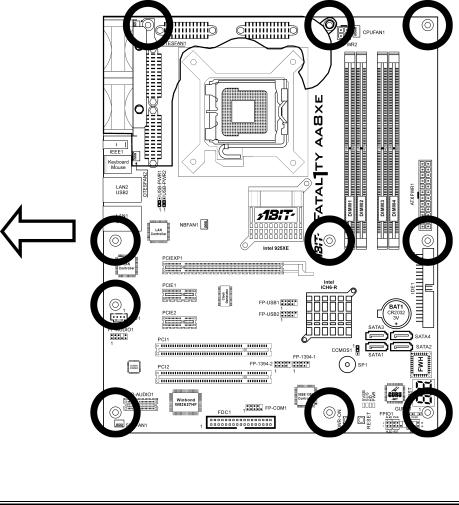
1-3. Layout Diagram
User’s Manual

1-6 |
Chapter 1 |
|
|
For more information:
www.abit.com.tw
Fatal1ty AA8XE
Hardware Setup |
2-1 |
|
|
Chapter 2. Hardware Setup
Before installation: Turn off the power supply switch (fully turn off the +5V standby power), or disconnect the power cord before installing or unplugging any connectors or add-on cards. Failing to do so may cause the motherboard components or add-on cards to malfunction or become damaged.
2-1. Install The Motherboard
Most computer chassis have a base with many mounting holes to allow the motherboard to be securely attached, and at the same time, prevent the system from short circuits. There are two ways to attach the motherboard to the chassis base:
1.use studs, or
2.use spacers
In principle, the best way to attach the board is to use studs. Only if you are unable to do this should you attach the board with spacers. Line up the holes on the board with the mounting holes on the chassis. If the holes line up and there are screw holes, you can attach the board with studs. If the holes line up and there are only slots, you can only attach with spacers. Take the tip of the spacers and insert them into the slots. After doing this to all the slots, you can slide the board into position aligned with slots. After the board has been positioned, check to make sure everything is OK before putting the chassis back on.
ATTENTION: To prevent shorting the PCB circuit, please REMOVE the metal studs or spacers if they are already fastened on the chassis base and are without mounting-holes on the motherboard to align with.
User’s Manual
2-2 |
Chapter 2 |
|
|
Before installing this motherboard, exam your chassis to ensure this motherboard fits into it.
1.Face the side of the I/O ports toward the rear part of the chassis.
2.Locate the screw holes on the motherboard and the chassis base.
3.Place all the studs or spacers needed on the chassis base, and then have them tightened.
4.Line up all the screw holes on the motherboard with those studs or spacers on the chassis.
5.Tighten all the screws.
As the Dual OTES Fan Duct takes up two screw-hole positions that are traditionally used for motherboard installation, please refer to the “ABIT Dual OTES” quick installation guide for details.
Fatal1ty AA8XE
Hardware Setup |
2-3 |
|
|
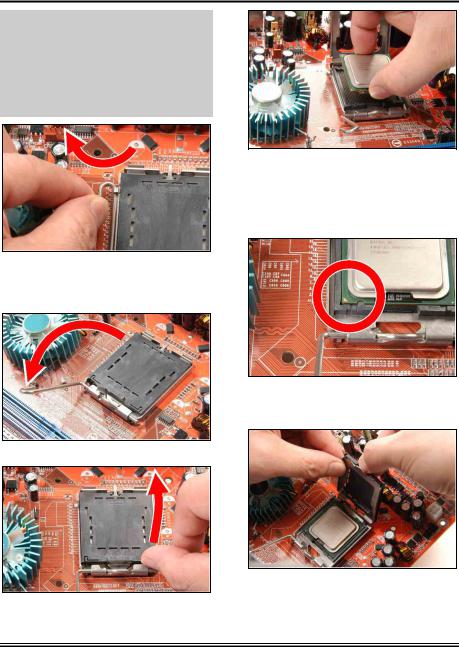
2-2. Install CPU, Heatsink and Fan Assembly
In order to protect the contact pins, please pay attention to these notices:
1.A maximum 20 cycles of CPU installation is recommended.
2.Never touch the contact pins with fingers or any object.
3.Always put on the cap when the CPU is not in use.
1. Place the board so as to let the lever hook of the socket is on your left side. Use your left thumb and forefinger to hold the lever hook, pull it away from the retention tab.
4. Use your right thumb and forefinger to grasp the CPU package. Be sure to grasp on the edge of the substrate, and face the Pin-1 indicator toward the bottom-left side. Aim at the socket and place the CPU package vertical down into the socket.
5. Visually inspect if the CPU is seated well into the socket. The alignment key must be located in the notch of package.
2.Rotate the lever to fully open position.
3. Use your right thumb on the bottom-right side of the load plate and lift it up to fully open position.
6. Use your left hand to hold the load plate, and use your right thumb to peel the cap off.
User’s Manual
2-4 |
Chapter 2 |
|
|
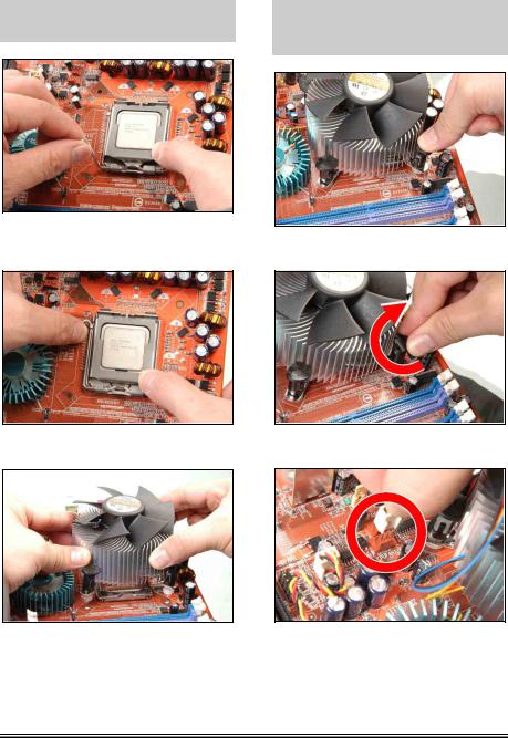
The cap plays an important role in protecting contact pins. In order to prevent bent pin, PUT ON the cap after operation or testing.
7. Lower the plate onto the CPU package. Engage the load lever while gently pressing down the load plate.
8. Secure the lever with the hook under retention tab.
9. Place the heatsink and fan assembly onto the socket. Align the four fasteners toward the four mounting holes on the motherboard.
For detailed information on how to install your heatsink and fan assembly, please refer to the instruction manual came packed with the heatsink and fan assembly you bought.
10. Press each of the four fasteners down into the mounting holes.
11. Rotate the fastener clock-wise to lock the heatsink and fan assembly into position.
12. Attach the four-pin power plug from the heatsink and fan assembly to the CPU FAN connector.
Fatal1ty AA8XE
Hardware Setup |
2-5 |
|
|
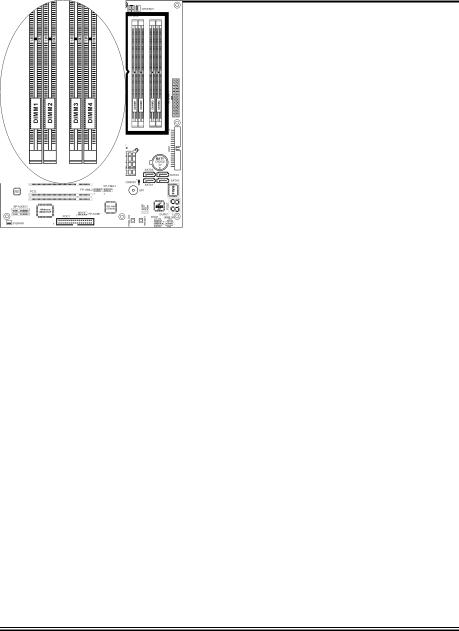
2-3. Install System Memory
The Intel 925XE Express Chipset MCH memory interface is designed with Flex Memory Technology supporting single-channel or dual-channel DDR2 memory configurations.
•To reach the optimum performance in dual-channel configurations, install identical DDR2 DIMM pairs for each channel.
•Install DIMMs with the same CAS latency. To reach the optimum compatibility, obtain memory modules from the same vendor.
•Due to chipset resource allocation, the system may detect less than 4GB of system memory in the installation of four 1GB DDR2 memory modules.
•Due to chipset limitation, 128MB DIMM modules or double-sided x16 memory chips are not supported.
There are several methods of different DDR2 configurations depending on how the DIMMs are populated on each system memory channel:
•[Single Channel]: only one channel is populated.
Method |
|
Channel A |
|
Channel B |
||
DIMM1 |
|
DIMM2 |
DIMM3 |
|
DIMM4 |
|
|
|
|
||||
1 |
512MB |
|
- |
- |
|
- |
2 |
- |
|
512MB |
- |
|
- |
3 |
- |
|
- |
512MB |
|
- |
4 |
- |
|
- |
- |
|
512MB |
5 |
512MB |
|
512MB |
- |
|
- |
6 |
- |
|
- |
512MB |
|
512MB |
User’s Manual
2-6 |
Chapter 2 |
|
|
•[Dual Channel Asymmetric]: both channels are populated, but each channel has a different amount of total memory. (Channel A≠Channel B)
Method |
|
Channel A |
|
Channel B |
||
DIMM1 |
|
DIMM2 |
DIMM3 |
|
DIMM4 |
|
|
|
|
||||
1 |
512MB |
|
- |
256MB |
|
- |
2 |
- |
|
256MB |
- |
|
512MB |
3 |
512MB |
|
- |
- |
|
256MB |
4 |
- |
|
256MB |
512MB |
|
- |
5 |
256MB |
|
256MB |
256MB |
|
- |
6 |
256MB |
|
256MB |
- |
|
256MB |
7 |
256MB |
|
- |
256MB |
|
256MB |
8 |
- |
|
256MB |
256MB |
|
256MB |
9 |
256MB |
|
256MB |
512MB |
|
512MB |
10 |
256MB |
|
256MB |
256MB |
|
512MB |
•[Dual Channel Symmetric]: both channels are populated where each channel has the same amount of total memory. (Channel A Channel B)
Method |
|
Channel A |
|
Channel B |
||
DIMM1 |
|
DIMM2 |
DIMM3 |
|
DIMM4 |
|
|
|
|
||||
1 |
512MB |
|
- |
512MB |
|
- |
2 |
- |
|
512MB |
- |
|
512MB |
3 |
512MB |
|
- |
- |
|
512MB |
4 |
- |
|
512MB |
512MB |
|
- |
5 |
256MB |
|
256MB |
512MB |
|
- |
6 |
256MB |
|
256MB |
- |
|
512MB |
7 |
512MB |
|
- |
256MB |
|
256MB |
8 |
- |
|
512MB |
256MB |
|
256MB |
9 |
512MB |
|
256MB |
512MB |
|
256MB |
10 |
256MB |
|
512MB |
256MB |
|
512MB |
Power off the computer and unplug the AC power cord before installing or removing memory modules.
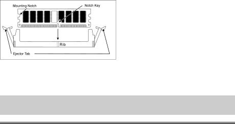
1.Locate the DIMM slot on the board.
2.Hold two edges of the DIMM module carefully, keep away of touching its connectors.
3.Align the notch key on the module with the rib on the slot.
4.Firmly press the module into the slots until the ejector tabs at both sides of the slot
automatically snaps into the mounting notch. Do not force the DIMM module in with extra force as the DIMM module only fit in one direction.
5.To remove the DIMM modules, push the two ejector tabs on the slot outward simultaneously, and then pull out the DIMM module.
ATTENTION: Static electricity can damage the electronic components of the computer or optional boards. Before starting these procedures, ensure that you are discharged of static electricity by touching a grounded metal object briefly.
Fatal1ty AA8XE
Hardware Setup |
2-7 |
|
|
2-4. Connectors, Headers and Switches
Here we will show you all of the connectors, headers and switches, and how to connect them. Please read the entire section for necessary information before attempting to finish all the hardware installation inside the computer chassis. A complete enlarged layout diagram is shown in Chapter 1 for all the position of connectors and headers on the board that you may refer to.
WARNING: Always power off the computer and unplug the AC power cord before adding or removing any peripheral or component. Failing to so may cause severe damage to your motherboard and/or peripherals. Plug in the AC power cord only after you have carefully checked everything.
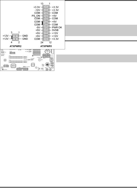
(1). ATX Power Input Connectors
This motherboard provides two power connectors to connect ATX12V power supplier.
NOTE: This 24-pin power connector “ATXPWR1” is compliant to the former 20-pin type. Pay attention to the orientation when doing so (Pin-11, 12, 23, and 24 should be left un-connected).
User’s Manual
2-8 |
Chapter 2 |
|
|
|
|
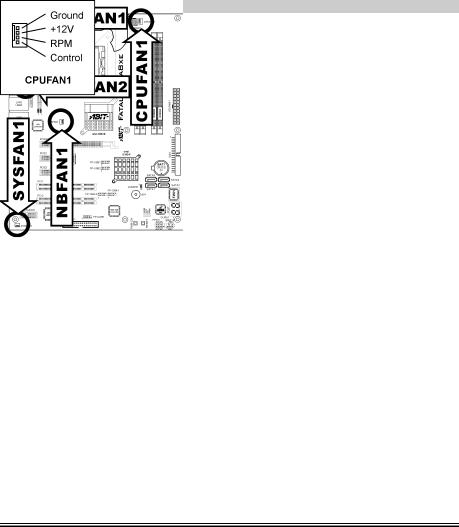
(2). FAN Power Connectors |
|
These connectors each provide power to the cooling fans installed in your system. |
|
• CPUFAN1: CPU Fan Power Connector |
|
• NBFAN1: Chipset Fan Power Connector |
|
• SYSFAN1: System Fan Power Connector |
|
• OTESFAN1, OTESFAN2: OTES Fan Power Connector |
|
WARNING: These fan connectors are not jumpers. DO NOT place jumper caps on these connectors.
Fatal1ty AA8XE
Hardware Setup |
2-9 |
|
|
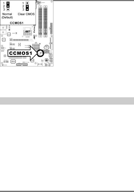
(3). CMOS Memory Clearing Header
This header uses a jumper cap to clear the CMOS memory.
•Pin 1-2 shorted (default): Normal operation.
•Pin 2-3 shorted: Clear CMOS memory.
WARNING: Turn the power off first (including the +5V standby power) before clearing the CMOS memory. Failing to do so may cause your system to work abnormally or malfunction.
User’s Manual
2-10 |
Chapter 2 |
|
|
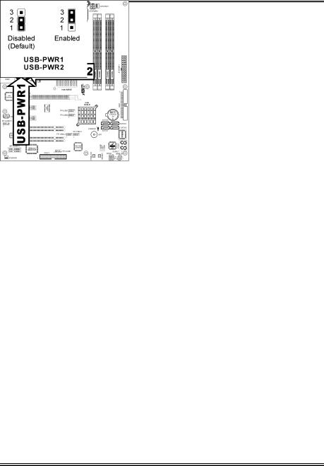
(4). Wake-up Header
These headers use a jumper cap to enable/disable the wake-up function.
•USB-PWR1:
Pin 1-2 shorted (default): Disable wake-up function support at USB1 port. Pin 2-3 shorted: Enable wake-up function support at USB1 port.
•USB-PWR2:
Pin 1-2 shorted (default): Disable wake-up function support at USB2 port. Pin 2-3 shorted: Enable wake-up function support at USB2 port
Fatal1ty AA8XE
Hardware Setup |
2-11 |
|
|
(5). Front Panel Audio Connection Header
This header provides the connection to audio connector at front panel.
|
Pin |
Pin Assignment |
Pin |
Pin Assignment |
|
|
|
|
|
|
1 |
MIC2 L (Microphone 2 Left) |
2 |
AGND (Analog Ground) |
|
|
|
|
|
|
3 |
MIC2 R (Microphone 2 Right) |
4 |
AVCC (Analog VCC Power) |
|
|
|
|
|
|
5 |
FRO-R (Front Right) |
6 |
MIC2_JD (Microphone 2 Jack |
|
Detect) |
|||
|
|
|
|
|
|
|
|
|
|
|
7 |
F_IO_SEN (Front I/O Sensor) |
|
|
|
|
|
|
|
|
9 |
FRO-L (Front Left) |
10 |
LINE2_JD (Line 2 Jack |
|
Detect) |
|||
|
|
|
|
|
|
|
|
|
|
User’s Manual
2-12 Chapter 2
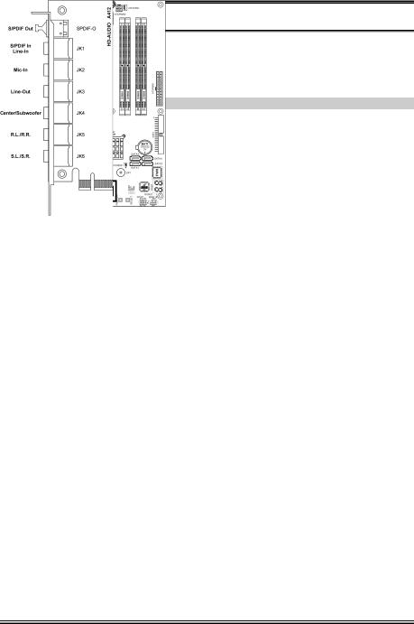
(6). Back Panel Audio Connection Slot
The slot “BP-AUDIO1” provides the audio input/output connection at back panel through an audio daughter-card.
NOTE: Install this daughter-card at slot “BP-AUDIO1”.
•S/PDIF Out: This connector provides an S/PDIF-Out connection through optical fiber to digital multimedia devices.
•S/PDIF In: This connector provides an S/PDIF-In connection through optical fiber to digital multimedia devices.
Line-In: Connects to the line out from external audio sources.
•Mic-In: Connects to the plug from external microphone.
•Line-Out: Connects to the front left and front right channel in the 7.1-channel or regular 2-channel audio system.
•Center/Subwoofer: Connects to the center and subwoofer channel in the 7.1 channel audio system.
•R.L./R.R. (Rear Left / Rear Right): Connects to the rear left and rear right channel in the 7.1 channel audio system.
•S.L./S.R. (Surround Left / Surround Right): Connects to the surround left and surround right channel in the 7.1 channel audio system.
Fatal1ty AA8XE
Hardware Setup |
2-13 |
|
|
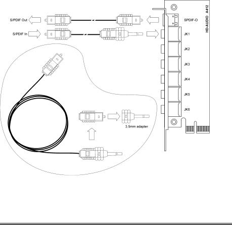
S/PDIF Connection:
Along with the motherboard package you can find an audio daughter-card and a roll of optical fiber cable for S/PDIF connection.
•S/PDIF Input Connection:
1.Plug the end with 3.5mm adapter into the [JK1] jack on this daughter-card. (This jack is used for either optical or line input.)
2.Remove the rubber protection-cap at the other end. Plug it into the [Digital-Out] (SPDIF-Out) jack on your digital multimedia device.
•S/PDIF Output Connection:
1.Pull out the 3.5mm adapter at one end. Keep this adapter with its protection-cap covered in save place. Plug the rest of this end into the [SPDIF-O] jack on this daughter-card.
2.Remove the rubber protection-cap at the other end. Plug it into the [Digital-In] (SPDIF-In) jack on your digital multimedia device.
User’s Manual
2-14 Chapter 2
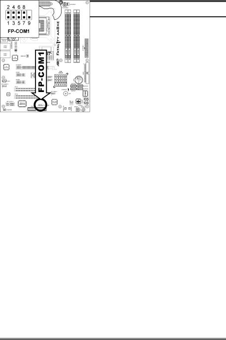
(7). Front Panel COM1 Connection Header
This header provides one additional COM1 port connection through an extension cable and bracket.
|
Pin |
Pin Assignment |
Pin |
Pin Assignment |
|
|
|
|
|
|
1 |
DCD (Data Carrier Detect) |
2 |
RXD (Receive-Data) |
|
|
|
|
|
|
3 |
TXD (Transfer-Data) |
4 |
DTR (Data-Terminal-Ready) |
|
|
|
|
|
|
5 |
GND |
6 |
DSR (Data-Set-Ready) |
|
|
|
|
|
|
7 |
RTS (Request-to-Send) |
8 |
CTS (Clear-to-Send) |
|
|
|
|
|
|
9 |
RI (Ring-Indicator) |
10 |
NC (No Connected) |
|
|
|
|
|
Fatal1ty AA8XE
Hardware Setup |
2-15 |
|
|
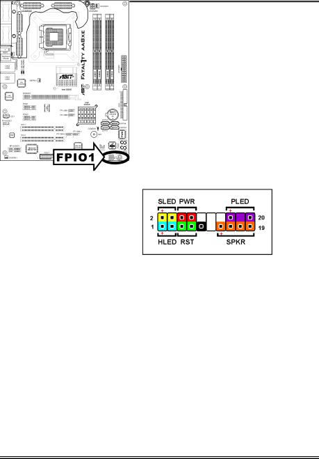
(8). Front Panel Switches & Indicators Headers
This header is used for connecting switches and LED indicators on the chassis front panel.
Watch the power LED pin position and orientation. The mark “+” align to the pin in the figure below stands for positive polarity for the LED connection. Please pay attention to connect these headers. A wrong orientation will only cause the LED not lighting, but a wrong connection of the switches could cause system malfunction.
•HLED (Pin 1, 3):
Connects to the HDD LED cable of chassis front panel.
•RST (Pin 5, 7):
Connects to the Reset Switch cable of chassis front panel.
•SPKR (Pin 13, 15, 17, 19):
Connects to the System Speaker cable of chassis.
•SLED (Pin 2, 4):
Connects to the Suspend LED cable (if there is one) of chassis front panel.
•PWR (Pin 6, 8):
Connects to the Power Switch cable of chassis front panel.
•PLED (Pin 16, 18, 20):
Connects to the Power LED cable of chassis front panel.
User’s Manual
2-16 |
Chapter 2 |
|
|
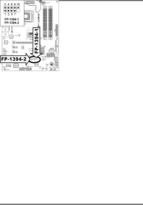
(9). Additional IEEE1394 Port Headers
These headers each provide one additional IEEE1394 port connection through an extension cable and bracket.
|
Pin |
Pin Assignment |
Pin |
Pin Assignment |
|
|
|
|
|
|
1 |
TPA0 + |
2 |
TPA0 - |
|
|
|
|
|
|
3 |
Ground |
4 |
Ground |
|
|
|
|
|
|
5 |
TPB0 + |
6 |
TPB0 - |
|
|
|
|
|
|
7 |
+12V |
8 |
+12V |
|
|
|
|
|
|
9 |
NC |
10 |
Ground |
|
|
|
|
|
Fatal1ty AA8XE
Hardware Setup |
2-17 |
|
|
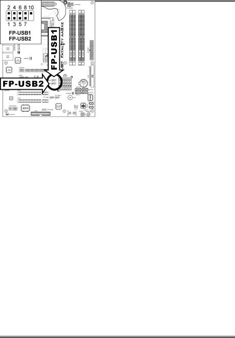
(10). Additional USB Port Headers
These headers each provide 2 additional USB 2.0 ports connection through an USB cable designed for USB 2.0 specifications.
|
Pin |
Pin Assignment |
Pin |
Pin Assignment |
|
|
|
|
|
|
1 |
VCC |
2 |
VCC |
|
|
|
|
|
|
3 |
Data0 - |
4 |
Data1 - |
|
|
|
|
|
|
5 |
Data0 + |
6 |
Data1 + |
|
|
|
|
|
|
7 |
Ground |
8 |
Ground |
|
|
|
|
|
|
9 |
NC |
10 |
NC |
|
|
|
|
|
User’s Manual
Loading...