


AW9D-MAX
Table of contents
 Loading...
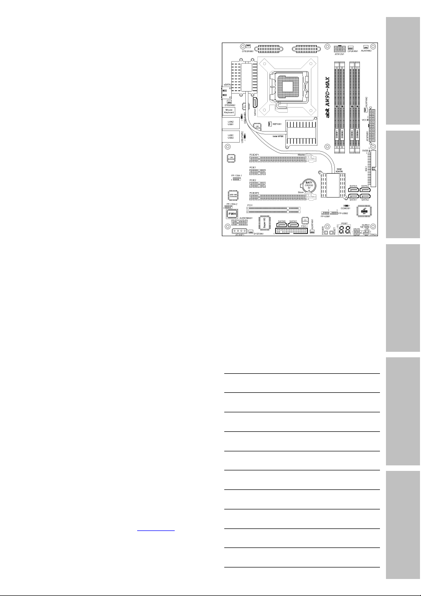
g
AW9D-MAX
Introduction
AW9D
Motherboard
Socket 775
Intel Core 2 Duo (Extreme Edition)
Intel Pentium Extreme Edition
Intel Pentium D
Intel Pentium 4
User’s Manual
Hardware Setup
BIOS Setup Driver & Utility CD Appendix
LGA775 ATX Motherboard
Intel 975X / ICH7R
About this Manual:
This user’s manual contains all the information you may
need for setting up this motherboard. To read the user’s
manual of PDF format (readable by Adobe Reader
the “Driver & Utility CD” into the CD-ROM drive in your
system. The auto-run screen will appear, click the
“Manual” tab to enter its submenu. If not, browse the
root directory of the CD-ROM via the File Mana
double click the “AUTORUN” file.
), place
er, and
1066MHz FSB
Dual DDR2 800
Dual PCI-E X16 Graphics Slots
Dual GbE LAN (AW9D-MAX)
8x SATA 3Gb/s (AW9D-MAX)
IEEE 1394 (AW9D-MAX)
HD 7.1 Audio
Silent OTES™ Technology
uGuru™ Technology

AW9D-MAX, AW9D
User’s Manual
English, 1
August, 2006
st
Edition
Copyright and Warranty Notice
The information in this document is subject to change without notice and does not represent a
commitment on part of the vendor, who assumes no liability or responsibility for any errors that may
appear in this manual.
No warranty or representation, either expressed or implied, is made with respect to the quality,
accuracy or fitness for any particular part of this document. In no event shall the manufacturer be
liable for direct, indirect, special, incidental or consequential damages arising from any defect or
error in this manual or product.
Product names appearing in this manual are for identification purpose only and trademarks and
product names or brand names appearing in this document are the property of their respective
owners.
This document contains materials protected under International Copyright Laws. All rights reserved.
No part of this manual may be reproduced, transmitted or transcribed without the expressed written
permission of the manufacturer and authors of this manual.
If you do not properly set the motherboard settings, causing the motherboard to malfunction or fail,
we cannot guarantee any responsibility.
ii AW9D-MAX, AW9D

Contents
Introduction
1. Introduction..................................................................... 1-1
1.1 Features & Specifications .............................................................1-1
1.2 Motherboard Layout.....................................................................1-3
1.2.1 AW9D-MAX.........................................................................1-3
1.2.2 AW9D ................................................................................1-4
2. Hardware Setup ............................................................... 2-1
2.1 Choosing a Computer Chassis.......................................................2-1
2.2 Installing Motherboard .................................................................2-1
2.3 Checking Jumper Settings ............................................................2-2
2.3.1 CMOS Memory Clearing Header and Backup Battery ..............2-3
2.3.2 Wake-up Header .................................................................2-5
2.4 Connecting Chassis Components...................................................2-6
2.4.1 ATX Power Connectors ........................................................2-6
2.4.2 Front Panel Switches & Indicators Headers............................2-7
2.4.3 FAN Power Connectors ........................................................2-8
2.5 Installing Hardware......................................................................2-9
2.5.1 CPU Socket 775 ..................................................................2-9
2.5.2 DDR2 Memory Slots ..........................................................2-12
2.5.3 PCI Express X16 Add-on Slots (Install Graphics Card) ..........2-14
2.5.4 AudioMAX Connection Slot ................................................. 2-16
2.6 Connecting Peripheral Devices .................................................... 2-19
2.6.1 Floppy and IDE Disk Drive Connectors ................................ 2-19
2.6.2 Serial ATA Connectors .......................................................2-20
2.6.3 Additional USB 2.0 Port Headers......................................... 2-21
2.6.4 Additional IEEE1394 Port Header........................................ 2-21
2.6.5 PCI Express X1 Add-on Slots .............................................. 2-22
2.6.6 PCI Add-on Slot ................................................................2-22
2.6.7 GURU Panel Connection Header ......................................... 2-23
2.7 Onboard Indicators and Buttons .................................................2-24
2.7.1 POST Code Displayer.........................................................2-24
2.7.2 Power Source Indicators .................................................... 2-25
2.7.3 Onboard Buttons...............................................................2-26
2.8 Connecting Rear Panel I/O Devices ............................................. 2-27
Hardware Setup
BIOS Setup Driver & Utility CD Appendix
3. BIOS Setup....................................................................... 3-1
3.1 µGuru™ Utility..............................................................................3-2
3.1.1 OC Guru .............................................................................3-2
AW9D-MAX, AW9D iii

3.1.2 ABIT EQ .............................................................................3-4
3.2 Standard CMOS Features............................................................ 3-11
3.3 Advanced BIOS Features ............................................................3-14
3.4 Advanced Chipset Features......................................................... 3-18
3.5 Integrated Peripherals................................................................ 3-20
3.6 Power Management Setup.......................................................... 3-26
3.7 PnP/PCI Configurations ..............................................................3-29
3.8 Load Fail-Safe Defaults ..............................................................3-31
3.9 Load Optimized Defaults ............................................................3-31
3.10 Set Password........................................................................... 3-31
3.11 Save & Exit Setup ....................................................................3-31
3.12 Exit Without Saving.................................................................. 3-31
4. Driver & Utility CD............................................................ 4-1
4.1 Intel Chipset Software Installation Utility .......................................4-2
4.2 Intel Matrix Storage Technology Driver..........................................4-3
4.3 Realtek Audio Driver ....................................................................4-4
4.4 Realtek LAN Driver.......................................................................4-5
4.5 Silicon Image 3132 SATA Driver....................................................4-6
4.6 Silicon Image 3132 SATA RAID Driver ...........................................4-7
4.7 USB 2.0 Driver.............................................................................4-8
4.8 ABIT µGuru Utility........................................................................4-8
4.9 Intel SATA RAID Driver Disk Maker ...............................................4-9
4.10 Sil3132 SATA RAID Driver Disk Maker........................................ 4-10
5. Appendix .......................................................................... 5-1
5.1 POST Code Definitions .................................................................5-1
5.1.1 AWARD POST Code Definitions.............................................5-1
5.1.2 AC2005 POST Code Definitions.............................................5-4
5.2 Troubleshooting (How to Get Technical Support?)..........................5-5
5.2.1 Q & A.................................................................................5-5
5.2.2 Technical Support Form ......................................................5-8
5.2.3 Universal ABIT Contact Information......................................5-9
iv AW9D-MAX, AW9D

1. Introduction
Introduction
1.1 Features & Specifications
CPU
• Designed for Intel Pentium 4 LGA775 processor with 1066/800 MHz FSB
• Supports Intel Core 2 Duo(Extreme Edition), Pentium Extreme Edition, Pentium D,
& Pentium 4 Processors
• Supports Enhanced Intel Speedstep Technology (EIST)
• Supports Intel Extended Memory 64 Technology (EM64T)
• Supports Intel Virtualization Technology
• Supports Intel Execute Disable Bit capability
• Supports Intel Hyper-Threading Technology
Chipset
• Intel 975X / Intel ICH7R
Memory
• Four 240-pin DIMM slots
• Supports Dual Channel DDR2 800/667 Un-buffered Non-ECC memory
• Supports maximum memory capacity up to 8GB
Graphics
• Supports Dual PCI-Express X16 slots (Dual ATI CrossFire VGA cards)
LAN
• Onboard dual PCI-E Gigabit LAN controllers support 10/100/1000Mb Ethernet (For
model “AW9D-MAX” only)
• Onboard PCI-E Gigabit LAN controller supports 10/100/1000Mb Ethernet (For model
“AW9D” only)
Audio
• ABIT AudioMAX HD 7.1 CH
• Supports auto jack sensing and optical S/PDIF In/Out
• Dolby Master Studio Certificated
Expansion Slots
• 2x PCI-E X16 slots
• 2x PCI-E X1 slots
• 1x PCI slot
• 1x AudioMAX slot
Internal I/O Connectors
• 1x Floppy port
• 1x ATA 100/66/33 IDE connector
AW9D-MAX, AW9D 1-1

• 7x SATA connectors (For model “AW9D-MAX” only)
• 4x SATA connectors (For model “AW9D” only)
• 2x USB 2.0 headers
• 2x IEEE1394 headers
Rear Panel I/O
• 1x PS/2 Keyboard connector
• 1x PS/2 Mouse connector
• 1x eSATA connector (For model “AW9D-MAX” only)
• 4x USB 2.0 connectors
• 2x RJ-45 Gigabit LAN connectors (For model “AW9D-MAX” only)
• 1x RJ-45 Gigabit LAN connector (For model “AW9D” only)
Serial ATA
- Connector “SATA1” ~ “SATA4”:
• 4x SATA 3Gb/s offered by Intel ICH7R supports RAID 0/1/0+1/5.
• Supports SATA AHCI, providing native command queuing and native hot plug.
- Connector “SATA5” and “SATA6”: (For model “AW9D-MAX” only)
• 2x SATA 3Gb/s offered by Silicon Image 3132 supports RAID 0/1
- Connector “SATA7” and “eSATA1”: (For model “AW9D-MAX” only)
• 2x SATA 3Gb/s offered by Silicon Image 3132 supports RAID 0/1
IEEE 1394 (For model “AW9D-MAX” only)
• Supports 2 Ports IEEE 1394 at 400Mb/s transfer rate
ABIT Engineered
• ABIT uGuru™ Technology
• ABIT Silent OTES
• ABIT AudioMAX Technology
™
Technology
Miscellaneous
• ATX form factor (305mm x 245mm)
※ Specifications and information contained herein are subject to change without
notice.
1-2 AW9D-MAX, AW9D
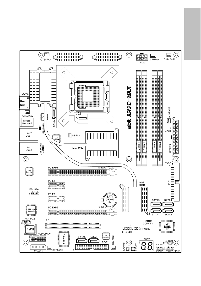
1.2 Motherboard Layout
Introduction
1.2.1 AW9D-MAX
AW9D-MAX, AW9D 1-3
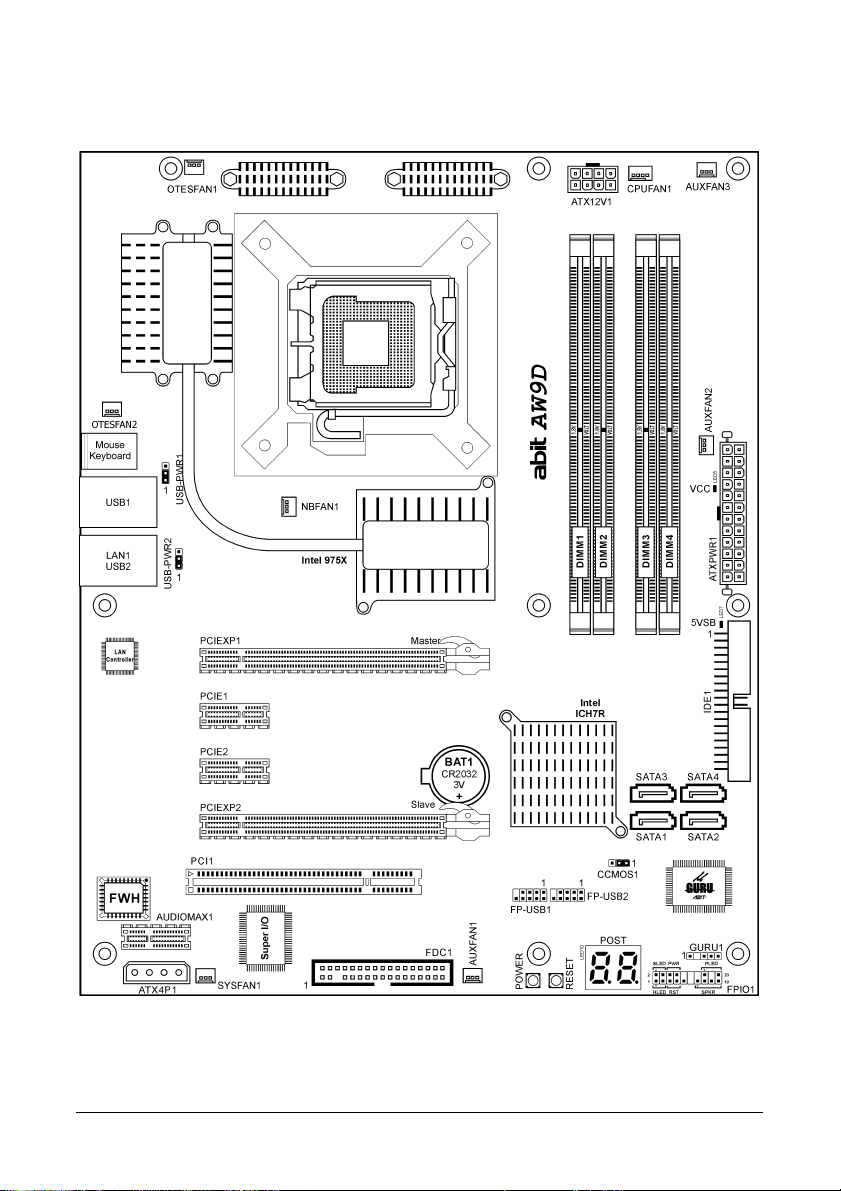
1.2.2 AW9D
1-4 AW9D-MAX, AW9D
2. Hardware Setup
In this chapter we will elaborate all the information you need upon installing this motherboard
to your computer system.
※ Always power off the computer and unplug the AC power cord before adding or
removing any peripheral or component. Failing to so may cause severe damage
to your motherboard and/or peripherals. Plug in the AC power cord only after
you have carefully checked everything.
The motherboard and its component layouts illustrated in this chapter were based
mainly on model “AW9D-MAX”, unless specifically stated.
2.1 Choosing a Computer Chassis
Hardware Setup
• This motherboard carries an ATX form factor of 305 x 245 mm. Choose a chassis big
enough to install this motherboard.
• As some features for this motherboard are implemented by cabling connectors on the
motherboard to indicators and switches or buttons on the chassis, make sure your chassis
supports all the features required.
• If there is possibility of adopting some more hard drives, make sure your chassis has
sufficient power and space for them.
• Most chassis have alternatives for I/O shield located at the rear panel. Make sure the I/O
shield of the chassis matches the I/O port configuration of this motherboard. You can find
an I/O shield specifically designed for this motherboard in its package.
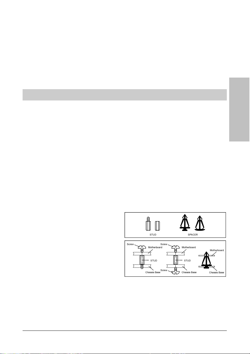
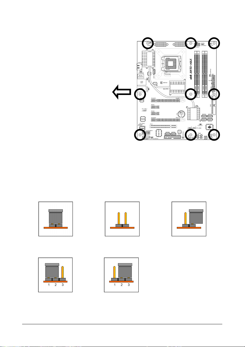
2.2 Installing Motherboard
Most computer chassis have a base with
many mounting holes to allow the
motherboard to be securely attached, and at
the same time, prevent the system from
short circuits. There are two ways to attach
the motherboard to the chassis base:
1. With studs,
2. Or with spacers
In principle, the best way to attach the board
is with use studs. Only if you are unable to
do this should you attach the board with
spacers. Line up the holes on the board with the mounting holes on the chassis. If the holes
line up and there are screw holes, you can attach the board with studs. If the holes line up and
there are only slots, you can only attach with spacers. Take the tip of the spacers and insert
them into the slots. After doing this to all the slots, you can slide the board into position aligned
with slots. After the board has been positioned, check to make sure everything is OK before
putting the chassis back on.
AW9D-MAX, AW9D 2-1
r
To install this motherboard:
1. Locate all the screw holes on
the motherboard and the
chassis base.
2. Place all the studs or spacers
needed on the chassis base
and have them tightened.
3. Face the motherboard’s I/O
ports toward the chassis’s rear
panel.
4. Line up all the motherboard’s
screw holes with those studs o
spacers on the chassis.
5. Install the motherboard with
screws and have them
tightened.
※ To prevent shorting the PCB circuit, please REMOVE the metal studs or spacers if
they are already fastened on the chassis base and are without mounting-holes
on the motherboard to align with.
Face the chassis’s rear panel.
2.3 Checking Jumper Settings
For a 2-pin jumper, plug the jumper cap on both pins will make it CLOSE (SHORT). Remove the
jumper cap, or plug it on either pin (reserved for future use) will leave it at OPEN position.
SHORT OPEN OPEN
For 3-pin jumper, pin 1~2 or pin 2~3 can be shorted by plugging the jumper cap in.
Pin 1~2 SHORT Pin 2~3 SHORT
2-2 AW9D-MAX, AW9D
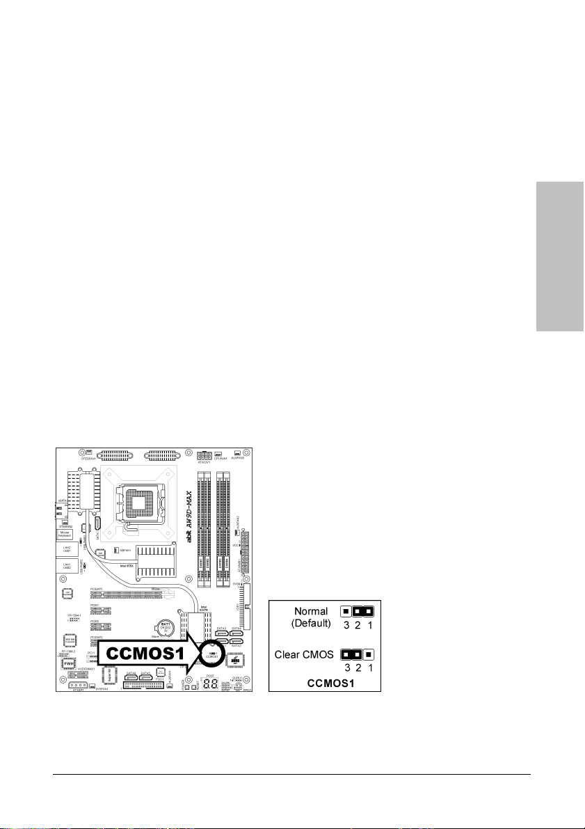
2.3.1 CMOS Memory Clearing Header and Backup Battery
The time to clear the CMOS memory occurs when (a) the CMOS data becomes corrupted, (b)
you forgot the supervisor or user password preset in the BIOS menu, (c) you are unable to
boot-up the system because the CPU ratio/clock was incorrectly set in the BIOS menu, or (d)
whenever there is modification on the CPU or memory modules.
This header uses a jumper cap to clear the CMOS memory and have it reconfigured to the
default values stored in BIOS.
• Pins 1 and 2 shorted (Default): Normal operation.
• Pins 2 and 3 shorted: Clear CMOS memory.
To clear the CMOS memory and load in the default values:
1. Power off the system.
2. Set pin 2 and pin 3 shorted by the jumper cap. Wait for a few seconds. Set the jumper cap
back to its default settings --- pin 1 and pin 2 shorted.
3. Power on the system.
4. For incorrect CPU ratio/clock settings in the BIOS, press <Del> key to enter the BIOS setup
menu right after powering on system.
5. Set the CPU operating speed back to its default or an appropriate value.
6. Save and exit the BIOS setup menu.
Hardware Setup
AW9D-MAX, AW9D 2-3
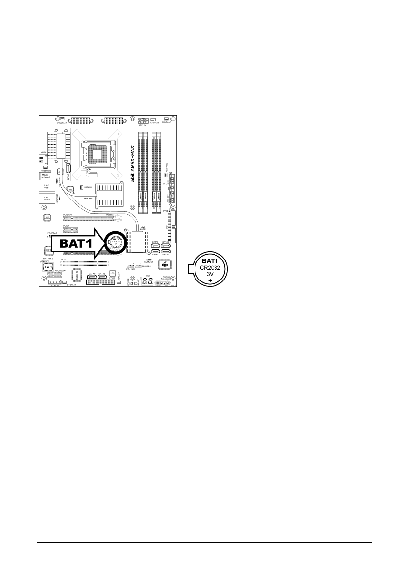
CMOS Backup Battery:
An onboard battery saves the CMOS memory to keep the BIOS information stays on even after
disconnected your system with power source. Nevertheless, this backup battery exhausts after
some five years. Once the error message like “CMOS BATTERY HAS FAILED” or “CMOS
checksum error” displays on monitor, this backup battery is no longer functional and has to
be renewed.
To renew the backup battery:
1. Power off the system and disconnect with AC power source.
2. Remove the exhausted battery.
3. Insert a new CR2032 or equivalent battery. Pay attention to its polarity. The “+” side is its
positive polarity.
4. Connect AC power source and power on the system.
5. Enter the BIOS setup menu. Reconfigure the setup parameters if necessary.
CAUTION:
※ Danger of explosion may arise if the battery is incorrectly renewed.
※ Renew only with the same or equivalent type recommended by the battery
manufacturer.
※ Dispose of used batteries according to the battery manufacturer’s instructions.
2-4 AW9D-MAX, AW9D
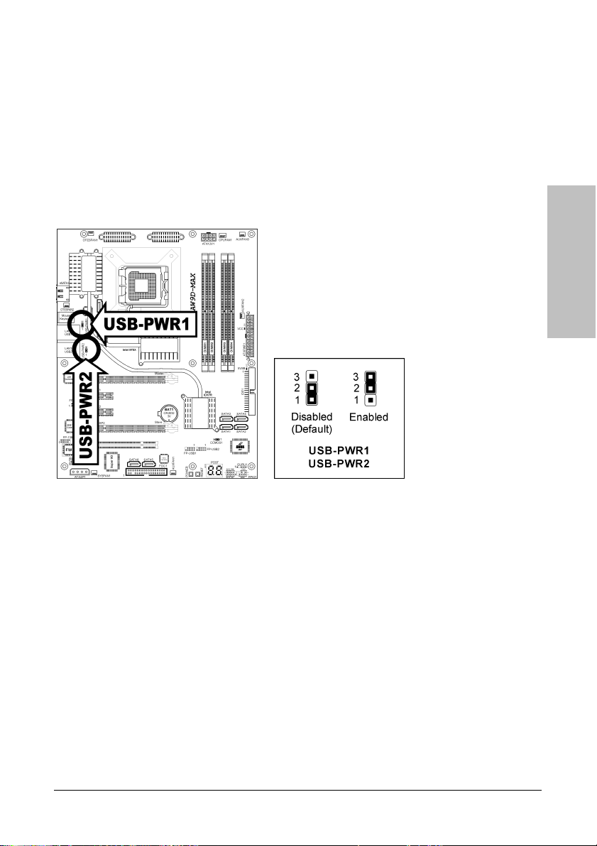
2.3.2 Wake-up Header
These headers use a jumper cap to enable/disable the wake-up function.
• USB-PWR1:
Pin 1-2 shorted (Default): Disable wake-up function support at USB1 port.
Pin 2-3 shorted: Enable wake-up function support at USB1 port.
• USB-PWR2:
Pin 1-2 shorted (Default): Disable wake-up function support at USB2 port.
Pin 2-3 shorted: Enable wake-up function support at USB2 port
Hardware Setup
AW9D-MAX, AW9D 2-5
2.4 Connecting Chassis Components
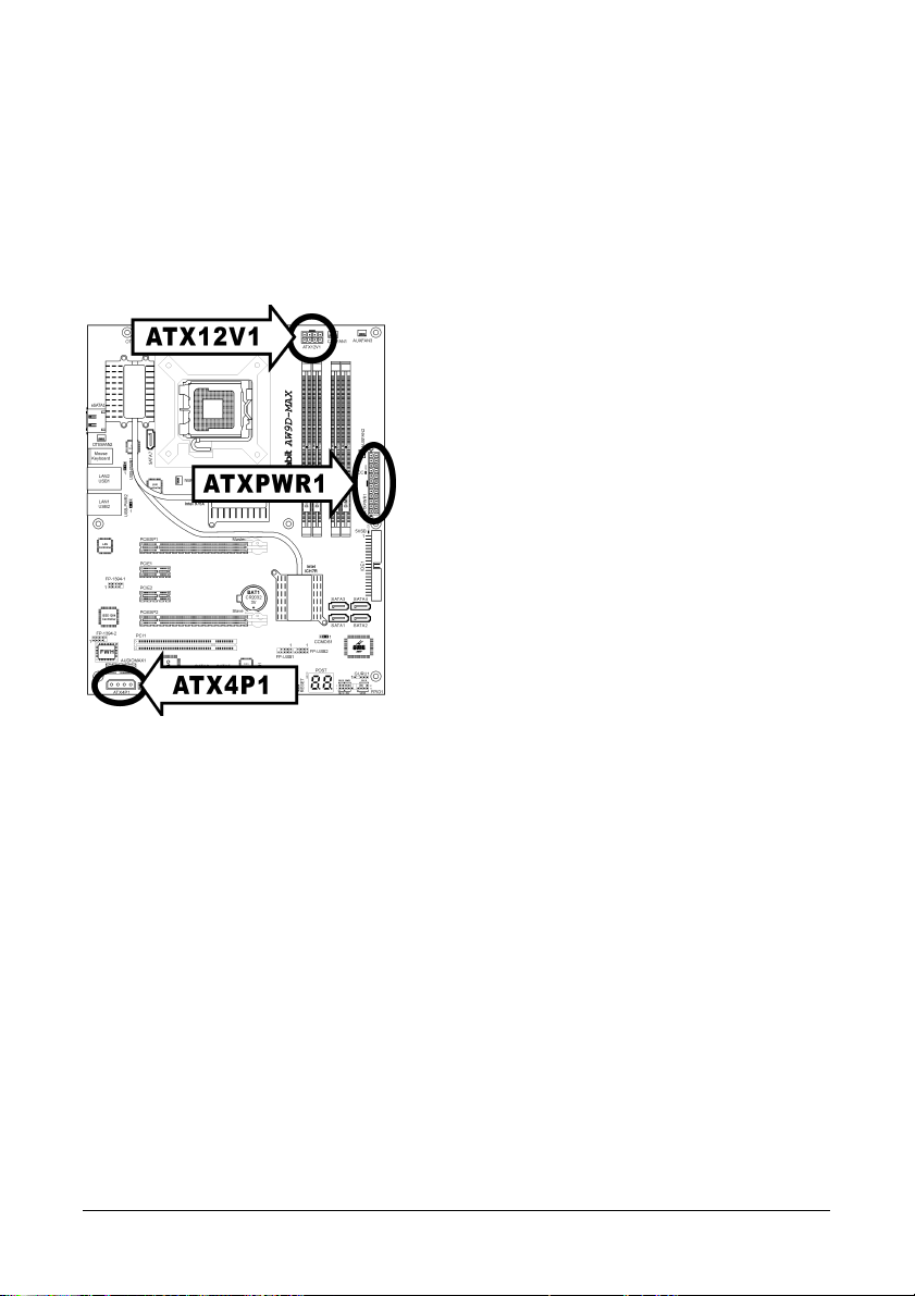
2.4.1 ATX Power Connectors
These connectors provide the connection from an ATX power supply. As the plugs from the
power supply fit in only one orientation, find the correct one and push firmly down into these
connectors.
ATXPWR1: ATX 24-Pin Power Connector
The power supply with 20-pin or 24-pin cables can both be connected to this 24-pin connector.
Connect from pin-1 for either type. However, a 20-pin power supply may cause the system
unstable or even unbootable for the sake of insufficient electricity. A minimum power of 300W
or higher is recommended.
ATX12V1: ATX 12V 8-Pin Power Connector
This connector supplies power to CPU. The system will not start without connecting power to
this one.
ATX4P1: Auxiliary 12V Power Connector
This connector provides an auxiliary power source for devices added on PCI Express slots.
2-6 AW9D-MAX, AW9D
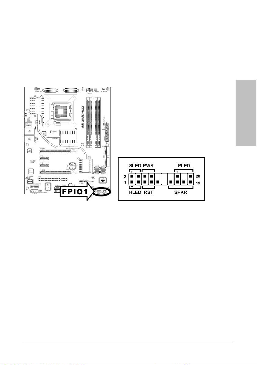
2.4.2 Front Panel Switches & Indicators Headers
This header is used for connecting switches and LED indicators on the chassis front panel.
Watch the power LED pin position and orientation. The mark “+” align to the pin in the figure
below stands for positive polarity for the LED connection. Please pay attention when connecting
these headers. A wrong orientation will only cause the LED not lighting, but a wrong connection
of the switches could cause system malfunction.
Hardware Setup
• HLED (Pin 1, 3):
Connects to the HDD LED cable of chassis front panel.
• RST (Pin 5, 7):
Connects to the Reset Switch cable of chassis front panel.
• SPKR (Pin 13, 15, 17, 19):
Connects to the System Speaker cable of chassis.
• SLED (Pin 2, 4):
Connects to the Suspend LED cable (if there is one) of chassis front panel.
• PWR (Pin 6, 8):
Connects to the Power Switch cable of chassis front panel.
• PLED (Pin 16, 18, 20):
Connects to the Power LED cable of chassis front panel.
AW9D-MAX, AW9D 2-7
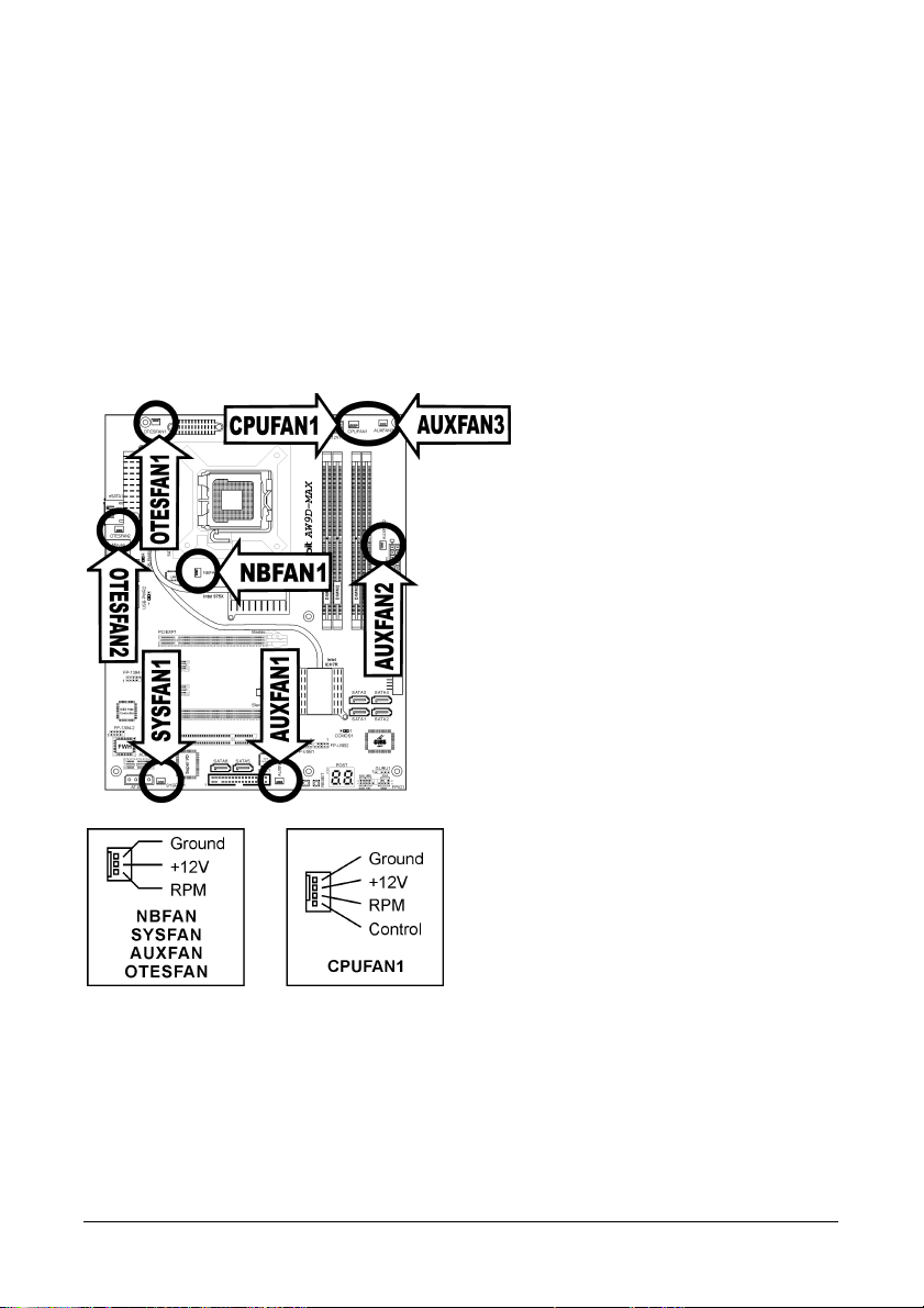
2.4.3 FAN Power Connectors
These connectors each provide power to the cooling fans installed in your system.
• CPUFAN1: CPU Fan Power Connector
• NBFAN1: Chipset Fan Power Connector
• SYSFAN1: System Fan Power Connector
• AUXFAN1~3, OTESFAN1~2: Auxiliary Fan Power Connector
※ These fan connectors are not jumpers. DO NOT place jumper caps on these
connectors.
2-8 AW9D-MAX, AW9D
2.5 Installing Hardware
※ DO NOT scratch the motherboard when installing hardware. An accidentally
scratch of a tiny surface-mount component may seriously damage the
motherboard.
※ In order to protect the contact pins, please pay attention to these notices:
1. A maximum 20 cycles of CPU installation is recommended.
2. Never touch the contact pins with fingers or any object.
3. Always put on the cap when the CPU is not in use.
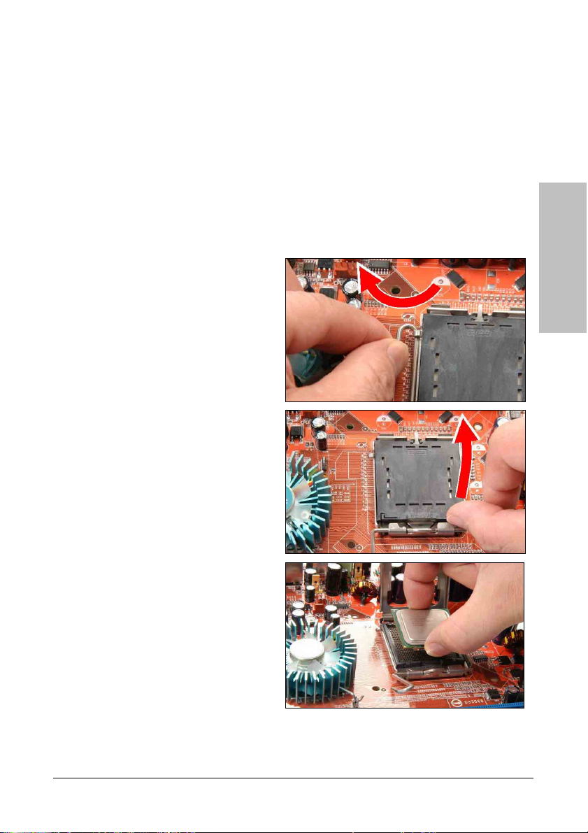
2.5.1 CPU Socket 775
1. Place the board so as to let the
lever-hook of the socket is on your left
side. Use your left thumb and forefinger
to hold the lever hook, pull it away from
the retention tab. Rotate the lever to
fully open position.
2. Use your right thumb on the
bottom-right side of the load plate and
lift it up to fully open position.
Hardware Setup
3. Use your right thumb and forefinger to
grasp the CPU package. Be sure to
grasp on the edge of the substrate, and
face the Pin-1 indicator toward the
bottom-left side. Aim at the socket and
place the CPU package vertical down
into the socket.
AW9D-MAX, AW9D 2-9
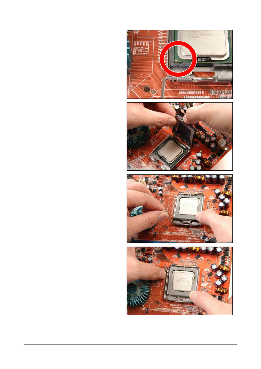
4. Visually inspect if the CPU is seated well
into the socket. The alignment key must
be located in the notch of package.
5. Use your left hand to hold the load
plate, and use your right thumb to peel
the cap off.
※ The cap plays an important role in
protecting contact pins. In order to
prevent bent pin, PUT ON the cap
after operation or testing.
6. Lower the plate onto the CPU package.
Engage the load lever while gently
pressing down the load plate.
7. Secure the lever with the hook under
retention tab.
2-10 AW9D-MAX, AW9D
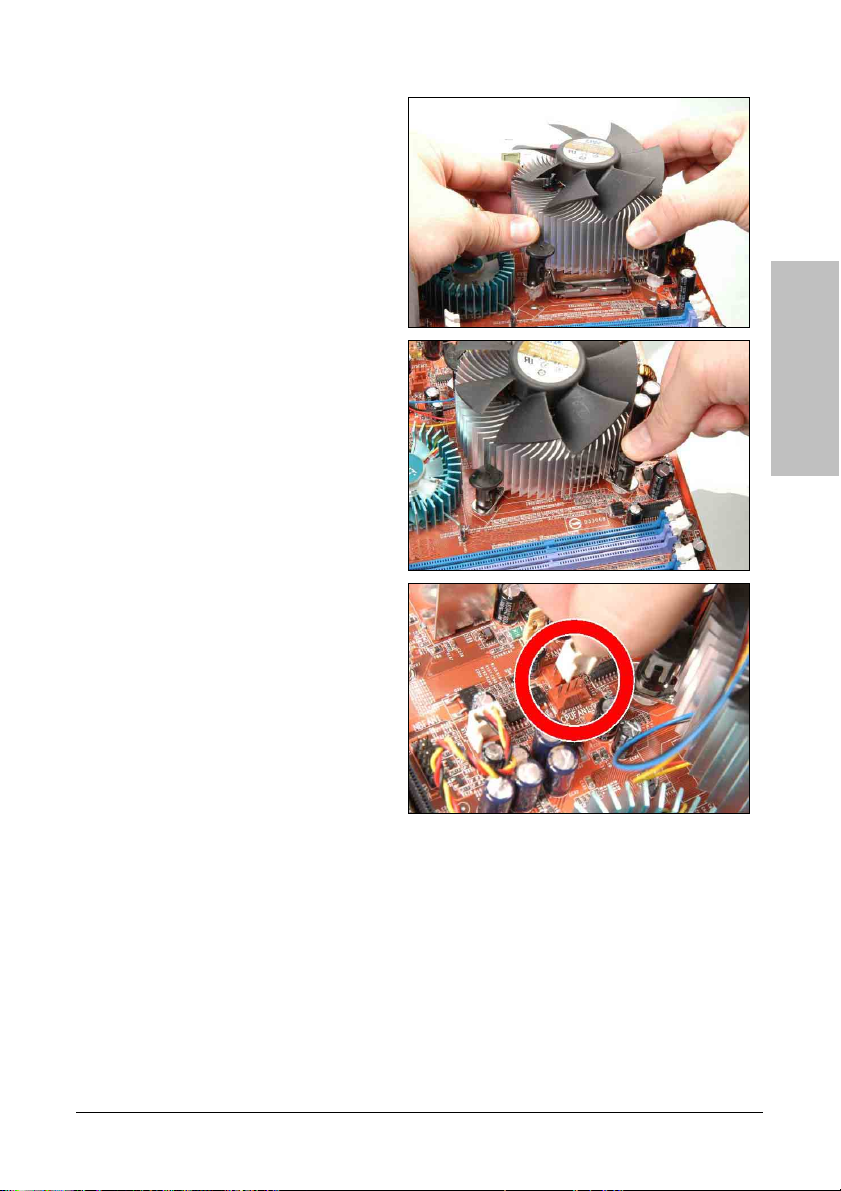
8. Place the heatsink and fan assembly
onto the socket. Align the four fasteners
toward the four mounting holes on the
motherboard.
9. Press each of the four fasteners down
into the mounting holes. Rotate the
fastener clock-wise to lock the heatsink
and fan assembly into position.
10. Attach the four-pin power plug from the
heatsink and fan assembly to the CPU
FAN connector.
Hardware Setup
※ The installation procedures vary with different types of CPU fan-and-heatsink
assembly. The one shown here is served for demo only. For detailed information
on how to install the one you bought, refer to its installation guidelines.
※ A higher fan speed will be helpful for better airflow and heat-dissipation.
Nevertheless, stay alert to touch any heatsink since the high temperature
generated by the working system is still possible.
AW9D-MAX, AW9D 2-11
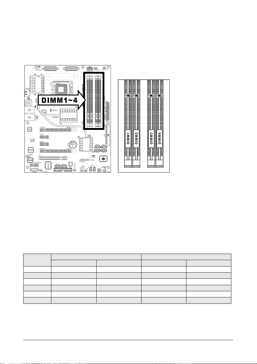
2.5.2 DDR2 Memory Slots
This motherboard provides four 240-pin DIMM slots for Dual Channel DDR2 800/667 memory
modules with memory expansion size up to 8GB.
• To reach the optimum performance in dual-channel configurations, install identical DDR2
DIMM pairs for each channel.
• Install DIMMs with the same CAS latency. To reach the optimum compatibility, obtain
memory modules from the same vendor.
• Due to chipset resource allocation, the system may detect less than 4GB of system memory
in the installation of four 1GB DDR2 memory modules.
There are several methods of different DDR2 configurations depending on how the DIMMs are
populated on each system memory channel:
• [Single Channel]: only one channel is populated.
Method
1 512MB - - 2 - 512MB - 3 - - 512MB 4 - - - 512MB
5 512MB 512MB - 6 - - 512MB 512MB
DIMM1 DIMM2 DIMM3 DIMM4
Channel A Channel B
2-12 AW9D-MAX, AW9D
• [Dual Channel Asymmetric]: both channels are populated, but each channel has a
different amount of total memory. (Channel A≠Channel B)
Method
1 512MB - 256MB 2 - 256MB - 512MB
3 512MB - - 256MB
4 - 256MB 512MB 5 256MB 256MB 256MB 6 256MB 256MB - 256MB
7 256MB - 256MB 256MB
8 - 256MB 256MB 256MB
9 256MB 256MB 512MB 512MB
10 256MB 256MB 256MB 512MB
• [Dual Channel Symmetric]: both channels are populated where each channel has the
same amount of total memory. (Channel A=Channel B)
Method
1 512MB - 512MB 2 - 512MB - 512MB
3 512MB - - 512MB
4 - 512MB 512MB 5 256MB 256MB 512MB 6 256MB 256MB - 512MB
7 512MB - 256MB 256MB
8 - 512MB 256MB 256MB
9 512MB 256MB 512MB 256MB
10 256MB 512MB 256MB 512MB
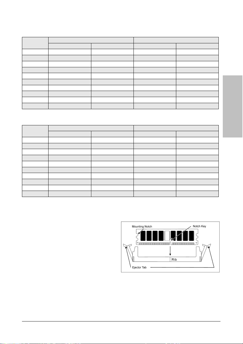
To install system memory:
1. Power off the computer and unplug the AC power cord before installing or removing
memory modules.
2. Locate the DIMM slot on the board.
3. Hold two edges of the DIMM module
carefully, keep away from touching its
connectors.
4. Align the notch key on the module with
the rib on the slot.
5. Firmly press the module into the slots
until the ejector tabs at both sides of the
slot automatically snap into the mounting
notch. Do not force the DIMM module in
with extra force as the DIMM module only fits in one direction.
6. To remove the DIMM modules, push the two ejector tabs on the slot outward
simultaneously, and then pull out the DIMM module.
※ Static electricity can damage the electronic components of the computer or
optional boards. Before starting these procedures, ensure that you are
discharged of static electricity by touching a grounded metal object briefly.
DIMM1 DIMM2 DIMM3 DIMM4
DIMM1 DIMM2 DIMM3 DIMM4
Channel A Channel B
Channel A Channel B
Hardware Setup
AW9D-MAX, AW9D 2-13
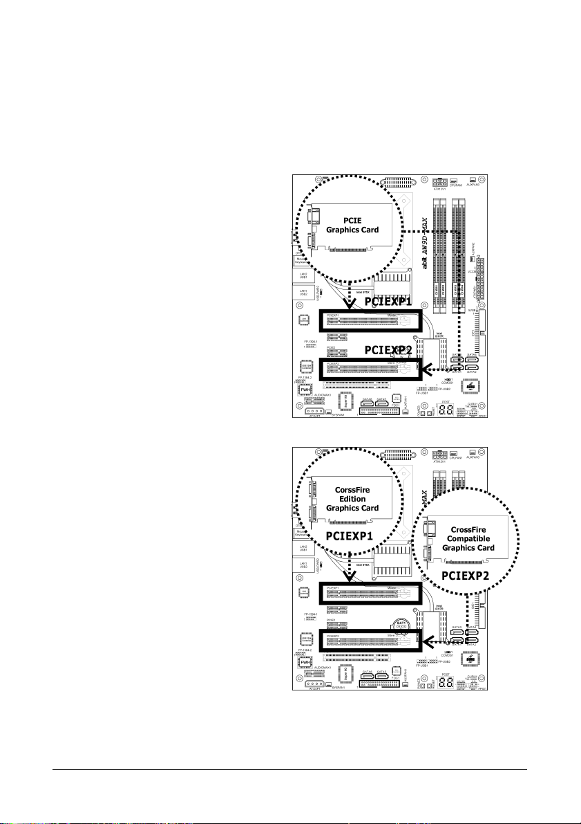
2.5.3 PCI Express X16 Add-on Slots (Install Graphics Card)
These slots support the connections of graphics cards that comply with PCI Express
specifications. This motherboard provides dual PCI-Express X16 slots for one or two graphics
cards installation:
One PCIE graphics card installation (Normal Mode):
Insert your PCIE graphics card into [PCIEXP1]
or [PCIEXP2] slot.
※ One PCIE graphics card installation
on the [PCIEXP2] slot supports the
speed up to x8 only.
Two PCIE graphics cards installation (CrossFire Mode):
™
Install one CrossFire
into [Master] slot (the PCIEXP1 slot on this
motherboard), and one CrossFire
graphics card into [Slave] slot (the PCIEXP2
slot on this motherboard).
※ The ATI CrossFire
currently supports the Microsoft
Windows XP with Service Pack 2
only.
Edition graphics card
™
Compatible
™
technology
2-14 AW9D-MAX, AW9D
To enable CrossFire Mode, you will need to:
• Prepare one CrossFire
• Make sure the graphics card driver supports the ATI CrossFire
latest driver from ATI website (http://www.ati.com
™
Edition graphics card and one CrossFire™ Compatible graphics card.
™
technology. Download the
).
• Make sure your power supply unit is sufficient to provide the minimum power required.
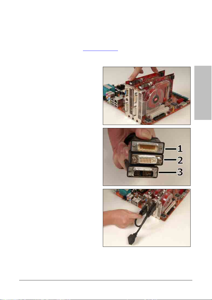
1. Insert the CrossFire
™
Edition graphics
card [Master Card] into the [PCIEXP1]
master slot on motherboard.
2. Insert the CrossFire
™
compatible PCI
Express graphics card (Slave Card) into
the [PCIEXP2] slave slot.
3. There are 3 connectors on the
™
DMS-59
-to-interconnect cable:
Connector 1: [DMS-59
™
] Male connector
Connector 2: [DVI-I] Female connector
Connector 3: [DVI-I] Male connector
Hardware Setup
4. Connect the DMS-59
DMS-59
™
connector on Master Card.
™
Male plug to the
5. Connect the DVI-I Male-end to the DVI-I
connector on Salve Card.
6. Connect the video output to your
monitor from the remaining DVI-I
Female-end.
※ The motherboard in this illustration is served for demonstration only, may not be
the same type or model as the one described in this user’s manual.
AW9D-MAX, AW9D 2-15
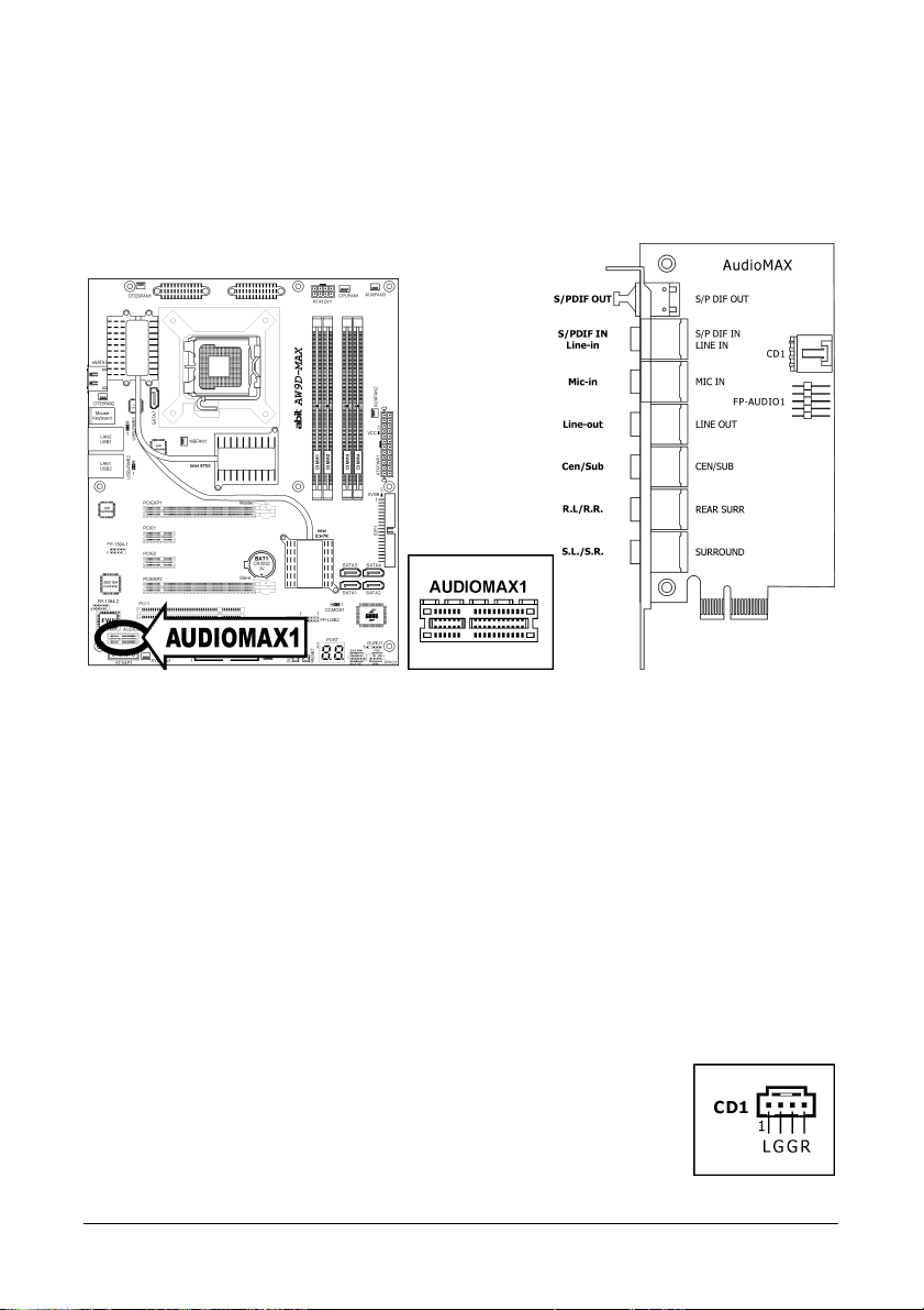
2.5.4 AudioMAX Connection Slot
This slot provides the audio input/output connection over the rear I/O part through an add-on
daughter-card. Find your “AudioMAX” daughter-card and its driver in the motherboard
package.
• S/PDIF Out: This connector provides an S/PDIF-Out connection through optical fiber to
digital multimedia devices.
• S/PDIF In: This connector provides an S/PDIF-In connection through optical fiber from
digital multimedia devices.
Line-In: Connects to the line out from external audio sources.
• Mic-In: Connects to the plug from external microphone.
• Line-Out: Connects to the front left and front right channel in the 7.1-channel or regular
2-channel audio system.
• Cen/Sub: Connects to the center and subwoofer channel in the 7.1-channel audio system.
• R.L./R.R. (Rear Left / Rear Right): Connects to the rear left and rear right channel in
the 7.1-channel audio system.
• S.L./S.R. (Surround Left / Surround Right): Connects to the surround left and
surround right channel in the 7.1-channel audio system.
• CD1: This connector connects to the audio output of internal CD-ROM
drive or add-on card.
2-16 AW9D-MAX, AW9D
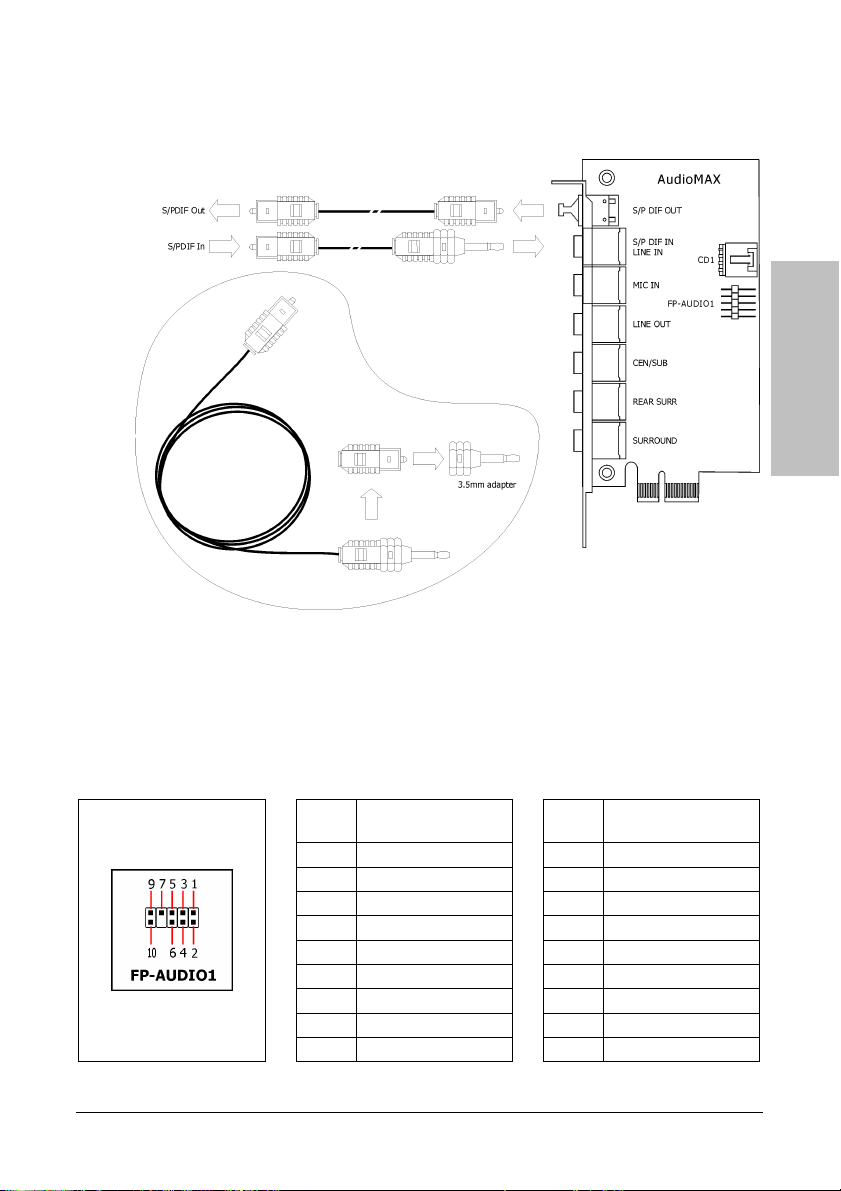
S/PDIF Connection:
In the motherboard package you can find one audio daughter-card and one optical-fiber cable.
Front Panel Audio Connection Header:
This header provides the front panel connection for HD (High Definition) Audio, yet for AC’97
Audio CODEC connection, you must carefully check the pin assignment before connecting from
the front panel module. An incorrect connection may cause malfunction or even damage the
motherboard.
※ Please do not connect the “Ground” cable or “USB VCC” cable from the front
panel module to the Pin 4 “AVCC” of this header.
Pin Assignment
Pin
1 MIC2 L 1 MIC In
2 AGND 2 GND
3 MIC2 R 3 MIC Power
4 AVCC 4 NC
5 FRO-R 5 Line Out (R)
6 MIC2_JD 6 NC
7 F_IO_SEN 7 NC
9 FRO-L 9 Line Out (L)
10 LINE2_JD 10 NC
(HD AUDIO)
Pin
Pin Assignment
(AC’97 AUDIO)
Hardware Setup
AW9D-MAX, AW9D 2-17
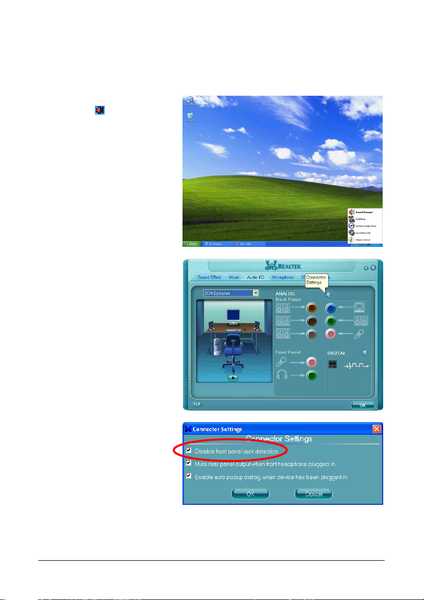
Driver Configuration for AC’97 audio connection:
The audio driver is originally configured to support HD Audio. For AC’97 audio connection, you
may:
1. Right-click the “Realtek HD Audio
Manager” icon
in system tray.
2. Click “Audio I/O” tab, and then click
“Connector Settings”.
3. Click “Disabled front panel jack
detection”, and then click “OK” to
confirm.
2-18 AW9D-MAX, AW9D
2.6 Connecting Peripheral Devices
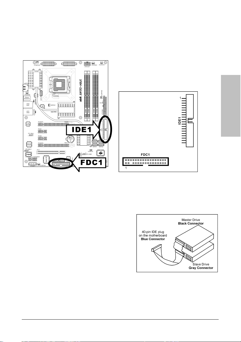
2.6.1 Floppy and IDE Disk Drive Connectors
The FDC1 connector connects up to two floppy drives with a 34-wire, 2-connector floppy cable.
Connect the single end at the longer length of ribbon cable to the FDC1 on the board, the two
connectors on the other end to the floppy disk drives connector. Generally you need only one
floppy disk drive in your system.
※ The red line on the ribbon cable must be aligned with pin-1 on both the FDC1
port and the floppy connector.
Each of the IDE port connects up to two IDE drives
at Ultra ATA/100 mode by one 40-pin, 80-conductor,
and 3-connector Ultra ATA/66 ribbon cables.
Connect the single end (blue connector) at the
longer length of ribbon cable to the IDE port of this
board, the other two ends (gray and black connector)
at the shorter length of the ribbon cable to the
connectors of your hard drives.
※ Make sure to configure the “Master” and “Slave” relation before connecting two
drives by one single ribbon cable. The red line on the ribbon cable must be
aligned with pin-1 on both the IDE port and the hard-drive connector.
Hardware Setup
AW9D-MAX, AW9D 2-19
Loading...