


Dynatel™ 2250E/2273E
Advanced Cable and
Fault Locator
Operators Manual
September 1999
78-8097-6500-7-B

TABLE OF CONTENTS |
|
Introduction ............................................................................... |
2 |
Installing or Replacing the Batteries ........................................ |
2 |
Initial Receiver Configuration .................................................. |
3 |
Receiver Battery Test ................................................................ |
3 |
Transmitter Battery Test ........................................................... |
4 |
Using External DC Power and 5 Watt Output .......................... |
4 |
Locating a Buried Cable ........................................................... |
5 |
Transmitter Setup ................................................................ |
5 |
Receiver Setup .................................................................... |
10 |
Determining Cable Depth and Current ..................................... |
13 |
Locating Sheath Faults.............................................................. |
14 |
Locating an Active Duct Probe ................................................. |
16 |
Locating EMS Markers ............................................................. |
17 |
Toning Aerial Faults .................................................................. |
18 |
Cable or Pair Identification ....................................................... |
19 |
Optional Accessories ................................................................. |
21 |
Technical Information ............................................................... |
22 |
Page 1

INTRODUCTION
The 3M™ Dynatel 2250E/2273E Advanced Cable and Fault Locator consists of a Transmitter and a Receiver for locating buried cables or Active Duct Probes (sondes). It also measures and pinpoints sheath faults in buried cables (2273E only) and conductor faults in aerial cables. The transmitter provides four frequencies to accommodate varying factors such as distance, cable type, or soil conditions. If desired, all four frequencies may be transmitted at once. The Transmitter also provides a separate Tone function for identifying cables and pairs. The Receiver provides four locating modes to accomplish fast or difficult tracing and to pinpoint or verify a conductor. The Receiver detects 50 or 60 Hz AC Power signals and low frequency (LF) radio signals re-radiated from local broadcast transmitters. It also measures the signal current in a conductor and displays its magnitude. The depth of buried cables or sondes may also be displayed.
Note: For more detailed locating instructions and advanced locating techniques, ask your 3M sales representative for a free publication called Cable and Pipe Locating Techniques.
INSTALLING OR REPLACING THE BATTERIES
6 'LR6' cells
Caution!
Do not connect batteries improperly, charge or dispose of in fire. Batteries may leak or explode and cause personal injury. Always remove batteries when storing the units.
Battery Disposal: Since regulations vary, consult applicable regulations or authorities before disposal.
Page 2

INITIAL RECEIVER CONFIGURATION
Display depth units (inches, feet and inches, or centimeters) may be changed while holding  and pressing
  . For each press, one of three units will display. To change the passive Power frequency, press and hold
  then press
  to toggle between 50 or 60 Hz as displayed in the lower left corner of the display.
To change the Null bar graph display mode, press and hold  then
then
press to toggle between normal Null bar graph display (Null flag will flash) and inverse Null bar graph display (Null flag is solid). See section
About Trace Modes (page 11) for further information.
RECEIVER BATTERY TEST
Battery
Indicator
Battery
Mark
The Receiver batteries are tested for two seconds every time the unit is turned on. The time interval can be extended by pressing and holding  . During the battery test, the bar graph should extend to the right of the battery level mark, otherwise replace the batteries.
Note: When batteries are low, the battery test indicator  will flash.
Page 3

TRANSMITTER BATTERY TEST
To test the Batteries, press and hold |
. Listen to the tone and watch |
the display. |
|
•solid tone and 'OK' indicates batteries good;
•beeping tone and 'LO' indicates batteries low;
•no tone and '- -' indicates replace batteries.
Note: The battery test indicates battery condition for normal output levels. if the unit resets when the high output level is selected, use the normal output level or replace the batteries.
USING EXTERNAL DC POWER AND 5 WATT OUTPUT
The Transmitter can be operated from and external 12VDC source as well as its internal batteries. Use the supplied cigarette lighter adapter cable to connect the DC power from a vehicle's battery source to the Transmitter's external power jack located next to the output jack.
Note: The internal batteries will not be recharged with external DC.
5 Watt Output
An external DC source is required for 5 watt output. To select 5 watt operation, press  once for high output (3W) and again for 5 watt operation. The High Output flag will turn on for 3W and flash for 5W.
Page 4

LOCATING A BURIED CABLE
Transmitter Setup
Note: Key descriptions can be found inside the Transmitter lid.
Perform a battery test and then connect the Transmitter using one of the three methods below to put tracing signal on a cable.
Danger!
Voltage higher than 240 volts will damage equipment and cause personal injury and death. Make all direct test connections before turning on the Transmitter. Then activate the Transmitter in the Ohms mode and check the display for voltage readings. Follow standard procedures for reducing the voltage.
Warning!
Potential for electrical shock exists when handling connecting cables while the Transmitter is in the TRACE, FAULT or TONE modes. Turn the transmitter off before handling connecting cables.
Page 5
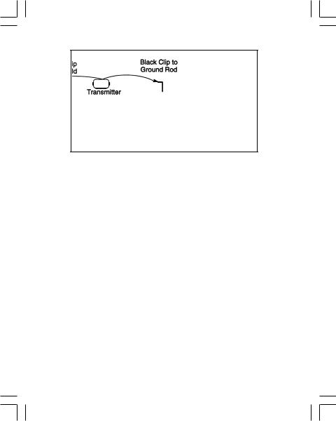
DIRECT CONNECT METHOD
Make sure the Transmitter is off. Plug the Direct Connect Cable into the front panel jack. Connect the Black clip to the ground rod. Place the ground rod in the earth perpendicular to the suspected cable path. If necessary, extend the black lead with the Ground Extension Cable. Next, remove the ground bonding and attach the Red clip to the shield.
Note: Never attach or remove the direct connect cable from the Transmitter front panel jack while the red and black clips are connected to a cable.
Press  to turn the Transmitter on in the Ohms mode
  . It will measure the continuity of the cable under test. The results are displayed in ohms and as a tone (solid tone = good ground; beeping tone = usable ground; no tone = poor or no ground).
Note: In the ohms mode, the Transmitter can detect voltage as well as ohms. If voltage is detected, the display will alternate between displaying ohms and volts. When displaying ohms, the flag over the  will be visible. When displaying volts, the flag over the 'V' will be visible. When the voltage magnitude is sufficient to impair the accuracy of the ohms measurement, only voltage will be displayed. If the voltage is AC, a sine wave
  will be visible on the display. If a high AC voltage is detected, a rapid beeping tone will be heard.
Page 6

Press |
to select Trace mode. Press again to select one or all of the |
four frequencies. The display will alternate between displaying the selected frequency and the output signal current. It is best to choose the lowest frequency for direct connect with far-end ground and a high frequency for direct connect with no far-end ground.
Press |
to select high output level for longer tracing distances and |
deep cables.
Transmitter setup is finished, now go to LOCATING A BURIED
CABLE - RECEIVER SETUP (PAGE 10).
Page 7
 Loading...