


Model 2100 (4100)
Overhead Projector
Service Manual
(Order the M2100 Illustrated Parts Breakdown separately - Stock # 78-6970-4936-5)
78-6970-1335-3 |
9/92 |
Visual Systems Division
3M Austin CenterBuilding
A145-5N-01
Austin, TX 78726-9000

MODEL 2100 OVERHEAD PROJECTOR
TABLE OF CONTENTS
Technical Support Hotline - 1-800-328-1371 (U.S. & Canada)
TITLE |
PAGE NUMBER |
|
|
|
|
|
Section 1 - Introduction ................................................................................. |
1-1 |
|
Specifications .............................................................................. |
1-1 |
|
Principles of Operation................................................................ |
1-3 |
|
- Optics ....................................................................................... |
1-3 |
|
- Cooling ..................................................................................... |
1-3 |
|
Section 2 - Operation and Maintenance ........................................................ |
2-1 |
|
Set Up Procedure ....................................................................... |
2-1 |
|
Lamp Management System ........................................................ |
2-3 |
|
Cleaning ...................................................................................... |
2-4 |
|
- Cleaning Stage and Fresnel Lens ............................................. |
2-4 |
|
- Mirrors ...................................................................................... |
2-4 |
|
Lubrication .................................................................................. |
2-5 |
|
Section 3 - Troubleshooting ........................................................................... |
3-1 |
|
Section 4 - Adjustments ................................................................................ |
4-1 |
|
General ....................................................................................... |
4-1 |
|
Tools Required ............................................................................ |
4-1 |
|
Projector Check-out Facilities...................................................... |
4-1 |
|
Optical Alignment........................................................................ |
4-3 |
|
- Square Image ........................................................................... |
4-3 |
|
- Focus Mechanism ..................................................................... |
4-4 |
|
- Aligning the Fresnel Lens ......................................................... |
4-4 |
|
Color Tuning Cable...................................................................... |
4-5 |
|
Post (Folding) .............................................................................. |
4-6 |
|
Lampchanger Cable .................................................................... |
4-6 |
|
Section 5 - Electrical Diagrams ..................................................................... |
5-1 |
|
Section 6 - Disassembly/Re-assembly .......................................................... |
6-1 |
|
Projection Head Assembly (Doublet) .......................................... |
6-1 |
|
Projection Head Assembly (Triplet) ............................................. |
6-1 |
|
Top Cover Assembly ................................................................... |
6-1 |
|
Fresnel Lens ............................................................................... |
6-1 |
|
Stage Glass ................................................................................ |
6-2 |
|
Focusing Assembly ..................................................................... |
6-2 |
|
Condenser Lens ......................................................................... |
6-3 |
|
Section 7 - Illustrated Parts Breakdown......................................................... |
7-1 |
|
(Published separately - Stock # 78-6970-4936-5) |
|
9/92
MODEL 2100 OVERHEAD PROJECTOR
SECTION 1 INTRODUCTION
This service manual contains servicing instruction, troubleshooting guide, adjustments, electrical diagrams, assembly/dis-assembly of parts and the illustrated parts list.
|
|
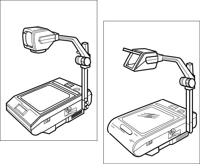
ANGULAR BODY |
|
|
|
|
(2130/4130, 2140/4140, 2160, 2170) |
|
|||
|
|
|
|
ROUND BODY |
|
|
|
|
|
(2150/4150, 2180) |
|
SPECIFICATIONS |
|
|
|
||
Physical |
|
|
|
|
|
Width |
- |
15.25" |
(387mm) |
|
|
Depth |
- |
20.25" |
(514mm) |
(Post in upright position) |
|
|
- |
26.25" |
(667mm) |
(Post in folded position) |
|
Height - |
7.75" |
(197mm) |
(Body) |
|
|
|
- |
30.75" |
(781mm) |
(Maximum, top of head) |
|
Weight - |
22 lbs. |
(10.0 Kg) |
2180 |
|
|
|
- |
25 lbs. |
(11.3 Kg) |
2130, 2140, 2150, 2160, 2170, 4130, 4140, 4150 |
|
|
|
|
|
9/92 |
1-1 |

MODEL 2100 OVERHEAD PROJECTOR
1-2 |
9/92 |
MODEL 2100 OVERHEAD PROJECTOR
Electrical |
2130/2140/2150 |
2160/2170/2180 |
2160/2170/2180 |
|
4130/4140/41 50 |
|
|
Voltage |
120/127/VAC |
100VAC |
220/230/240VAC |
Frequency |
60HZ |
50/60HZ |
50HZ |
Current Rating |
3.0 Amps |
3.6 Amps |
1.7 Amps |
Power Cord |
14-1/2' (4.4mm) |
14-1/2' (4.4mm) |
14-1 /2' (4.4mm) |
Agency Approval |
UL, CSA |
------- |
VDE, NEMKO, |
|
|
|
SETI |
Fuse |
------- |
F4 Amp - 250 Volt |
SEMKO, SEV |
|
F4 Amp - 250 Volt |
||
|
|
|
Mechanical
Safety interlock: Shuts off power to the projector when the top cover assembly is opened.
Safety thermostat: Cuts power to the lamp if the projector exceeds safe operating temperature.
Color tuning knob: Allows projector to be easily color tuned for any screen size 1.0m x 1.0m (40" x 40") to 2.8m x 2.8m (110" x 110").
Projection Head Tilt - 0° - 20° (All Heads)
Lamp Changer - when lamp burns out, switch to standby lamp.
Optical
Lamp: ANSI Code FNT, 24 Volt, 275 Watt
Lamp Life: 75 Hours |
|
|
|
|
2130/2140/2150 |
2160/2170/2180 |
|
|
4130/41 40/4150 |
|
|
Illumination: |
|
2000 lumens typical; |
2100 lumens typical; |
1800 lumens minimum; 1900 lumens minimum;
Mirrors: Chassis mirror is second surface high reflective type. (After serial no. 435242) Projection mirror is front surface high reflective type.
|
2130, 2140, 2160, 2170 |
2150, 2180 |
||
|
|
4130/4140 |
4150 |
|
Head, Projection: |
|
355mm (14.0" F.L.) |
327mm (12.9" F.L.) |
|
|
|
Doublet |
Triplet - w/focus |
|
|
|
293mm (11.5" F.L.) |
correction |
|
|
|
Singlet |
330mm (13" F.L.) |
|
|
|
|
|
After serial no. 411964 |
|
2130/21 40/2150 |
2160/2170/2180 |
||
|
4130/41 40/4150 |
|
||
Stage: |
|
267mm x 267mm |
285mm x 285mm |
|
Transmissive |
|
(10.5" x 10.5") |
(11.2" x 11.2") |
|
Aperture |
|
|
|
|
9/92 |
1-2 |
MODEL 2100 OVERHEAD PROJECTOR
PRINCIPLES OF OPERATION
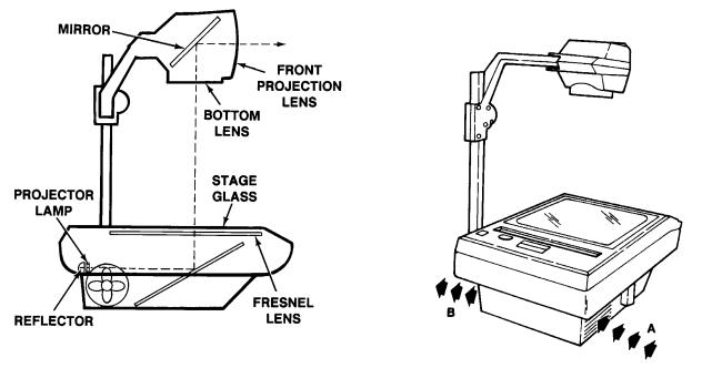
Optics (See Figure 1-2)
The light source for the Overhead Projector is 275 watt, 24 volt, Tungsten Lamp listed as ANSI Code FNT and rated at 75 hours. An external reflector is needed with this lamp.
Care should be exercised to prevent excessive vibration or jarring of the projector when the lamp is on. The lamp filament becomes more brittle at the operating temperature of the projector and shocks may cause premature failure of the lamp.
The glass envelope should not be touched by the fingers when inserting the lamp in the lampholder. Oils on the skin may combine with the glass to form blisters which also will shorten the life of the lamp.
The Fresnel lens, located above the lamp and directly beneath the projection stage, is a condensing lens which consists of a series of concentric rings, each of which has a surface curvature similar to that of a thick smooth lens. The Fresnel lens is made of plastic and may be severely damaged if the fan is stopped or the paths of cooling air blocked. Proper alignment and direction of the Fresnel lens is essential in order to maintain the resolution and brightness
The stage glass provides a convenient flat surface for placing transparencies and other materials to be projected. Because the light passes through the stage, these projection materials must be transparent.
There are two (2) different projection head assemblies available for the projector. One is an Open Triplet Head with focus correction which has a triplet lens and front surface mirror and the second a closed Doublet Head which has one or two condensing lens(es) and a front surface mirror. The projection head is located directly over the center of the Fresnel Lens. The projector is focused by raising or lowering the projection head.
Proper alignment of the optical components and a clean machine are essential if the maximum operating capabilities of the overhead projector are to be realized. Cleaning and alignment procedures are discussed in Sections 2 and 4 inclusive.
Cooling (See Figure 1-3)
Cooling of the overhead projector is accomplished by a motor-driven fan located next to the lamp housing. The cooling air enters the projector through opening “A” and exits through opening “B.” (See Figure 1-3) It’s important that the flow of cooling air not be restricted either by placing projector too close to a wall (about one foot
foreign
1-3 |
9/92 |
MODEL 2100 OVERHEAD PROJECTOR
SECTION 2 - OPERATION AND MAINTENANCE
SET UP PROCEDURE
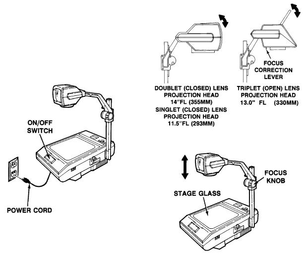
1 . Connect the power cord to a properly grounded electrical outlet. (Electrical requirements are listed on the serial plate located under the base of the projector.)
2.Place the projector on a level surface and turn the projector on by pushing down on the ON/OFF switch.
CAUTION!
Do not look in the front projection lens when lamp is on.
3. Adjust the image to the screen elevation by moving the front projection lens upward or downward on the DOUBLET HEAD
ASSEMBLY and the mirror on the TRIPLET HEAD ASSEMBLY. (See
Figure 2-2)
4.Place a transparency on the stage glass and focus the projected image by rotating the Focus Knob. (See Figure 2-3)
5.To maintain top to bottom focus when the screen is not perpendicular to the projected image, engage the FOCUS CORRECTION LEVER located on the under side of the TRIPLET HEAD ASSEMBLY using the following procedure:
NOTE
|
THE PROJECTION SCREEN |
|
|
9/92 |
MUST BE IN THE VERTICAL |
2-1 |
|
POSITION. |
|||
|
|
MODEL 2100 OVERHEAD PROJECTOR
A.Pull the mirror down as the FOCUS CORRECTION LEVER is pushed to the rear of the head assembly.
B.Raise the mirror back to the original position and refocus using the FOCUS KNOB.
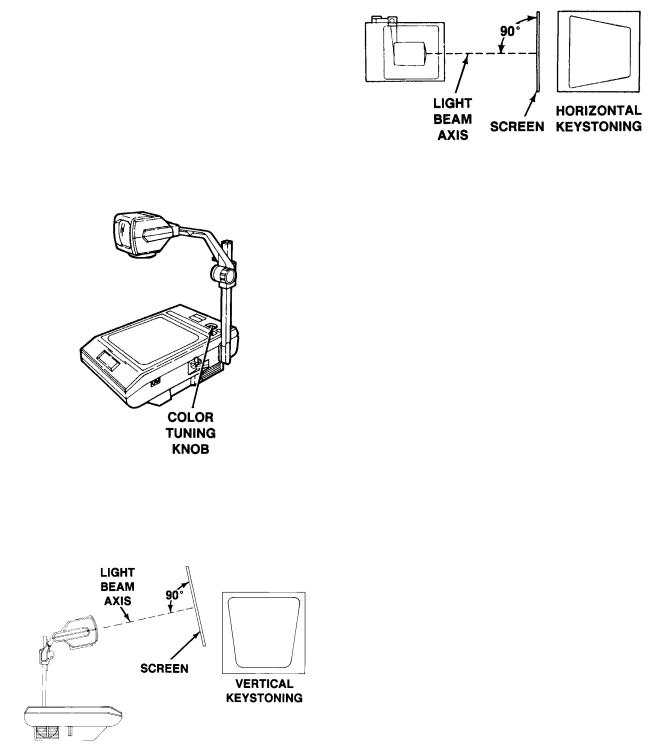
6.Rotate the Color Tuning Knob until the projected image is free of any
yellow or blue corners.
-To remove blue corners, rotate the dial counterclockwise.
-To remove yellow corners, rotate the dial clockwise.
7.Correct any vertical keystoning by tilting the screen until it is perpendicular to the light beam axis.
Correct any horizontal keystoning by moving the projector until it is perpendicular with the screen.
2-2 |
9/92 |
MODEL 2100 OVERHEAD PROJECTOR
LAMP MANAGEMENT SYSTEM
(Lamp Indicator)
Pertains only to models equipped with lamp indicators. (2130/4130 - No holes, opaque)
NOTE
When the projector is turned on, the red X will momentarily light. This is a characteristic of the projector.
The Lamp Indicator indicates status of projection lamp as defined on the following labels:
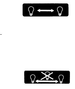
METHOD 1
A red X will appear on the lamp symbol when that lamp is burned out. Switch to the standby lamp. The X will continue to light until the defective lamp is changed.
METHOD 2
A red X will appear between the two lamp symbols when a lamp is burned out. Switch to the standby lamp. The X will continue to light until the defective lamp is changed.
NOTE
The Overhead Projector must remain on for 2 to 3 minutes after a lamp burns out. This will allow the fan to cool the burned-out lamp and prevent burned fingers. Unplug the unit before replacing the lamp.
9/92 |
2-3 |
 Loading...