


Installation Guide
OfficeConnect®
Managed Gigabit Switch (3CDSG8)
INTRODUCTION
About This Guide:
Thank you for purchasing the 3Com® OfficeConnect® Managed Gigabit Switch. This high quality, Gigabit Ethernet Switch is an easy, efficient way of creating or expanding an existing network and managing it centrally. The Switch’s Gigabit ports provide support for bandwidth intensive applications, and allow high speed connections to servers, and to the rest of the network. An example configuration is shown in Figure 1.
GreenConnect
Your OfficeConnect Gigabit Switch employs a number of initiatives to ensure your product uses the least amount of power possible:
1.High Efficiency Power Adapter
The Power Adapter is a model specially designed to meet the Energy Star™ requirements for operating efficiency and also very low standby power when not connected to the switch. These two features ensures your power adapter now uses substantially less power than a conventional linear adapter.
2.Energy Saving Modes
Your OfficeConnect Gigabit Switch employs the latest technology to minimise the amount of power it consumes.
When a port on the switch is not connected to a cable, or the link partner is turned off or removed, the switch reduces the power on that port until it is connected again. Also the switch detects the length of cable connected to its port and optimizes the power on the port to reach the end device. Thus for shorter cables lengths it will reduce the power output thereby achieving further reduction in power consumption.
You can be confident that your Switch will be taking the least amount of power but still providing the performance that you have come to expect from OfficeConnect.
The Switch is compact and attractively designed for desktop use. It can be used with other units in the OfficeConnect family, which include Cable/DSL gateways, wireless devices, Fast Ethernet and Gigabit Ethernet switches. The OfficeConnect family is a fully integrated system, enabling you to share computer resources, and take advantage of new technologies as your network grows.
Your Package Contains:
•OfficeConnect Switch
•Power adapter for use with the Switch
•Four rubber feet
•This Installation Guide including Support and Safety Information
•CD Containing a User Guide and Application software
•Warranty flyer
About This Guide
This guide will use the term Switch when referring to the OfficeConnect managed Gigabit Switch.
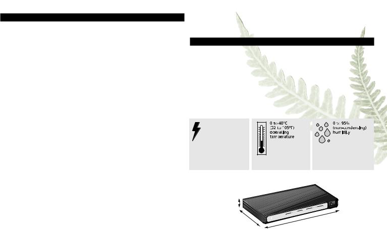
DIMENSIONS AND STANDARDS
Dimensions and Operating Conditions
Standards |
|
Functional: |
ISO 8802/3, IEEE 802.3, 802.3u |
Safety: |
UL 60950-1, EN 60950-1, CSA 22.2 #60950-1, IEC60950-1 |
EMC: |
EN 55022 Class A, EN 55024, |
|
FCC Part 15 Class A* ICES-003 Class A |
Environmental: |
EN 60068 (IEC 68) |
* Refer to Regulatory Notices in the Support and Safety Information Section.
Managed Gigabit Switch 8
7.64W, 26.1 BTU/hr power requriement
Height:
27 mm (1.06 in)
Depth:
135.4 mm (5.33 in)
|
|
|
|
|
|
Port |
|
|
|
|
|
3 |
4 |
|
|
|
1 |
2 |
Yellow |
|
|
|
Module |
Gree |
n = 1000M, |
|
|
Power |
Status |
Active |
|
|
|
|
Status |
|
7 |
5 |
6 |
Flash |
= 10/100 |
M, |
8/SFP = Activity
|
|
|
|
|
|
|
3CDSG8 |
|
|
|
|
|
|
|
|
On = Full |
|
|
|
|
Duplex |
|
|
Off = Half |
||
|
|
|
6 |
7 |
8 |
Switch |
||
|
|
|
4 |
5 |
d Gigabit |
|||
1 |
2 |
3 |
|
nnect |
Manage |
|
|
|
|
|
OfficeCo |
|
|
|
|
|
|
Width:
225 mm (8.08 in)
2
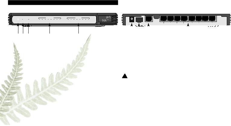
ABOUT YOUR SWITCH
OfficeConnect Managed Gigabit Switch - Front |
OfficeConnect Managed Gigabit Switch - Rear |
|
|
|
|
|
|
Port Status |
|
|
|
|
|
|
Duplex |
|
|
|
3CDSG8 |
||
|
|
|
|
|
|
|
|
|
|
|
|
|
|
|
On = Full |
||||
|
|
|
|
|
|
|
|
|
|
|
|
|
|
|
|
|
|
|
|
Power |
Status |
Module |
1 |
2 |
3 |
4 |
5 |
6 |
7 |
8/SFP |
1 |
2 |
3 |
4 |
5 |
6 |
7 |
8 |
Off = Half |
|
|
Active |
Green = 1000M, Yellow = 10/100M, Flash = Activity |
|
|
OfficeConnect Managed Gigabit Switch |
|||||||||||||
|
|
|
|
|
|||||||||||||||
1 |
2 |
3 |
4 |
5 |
POWER |
SFP |
CONSOLE |
|
|
|
|
|
|
|
|
|
|
|
|
|
6 |
|
|
7 |
|
8 |
|
9 |
|
|
|
|
|
1Power LED
Green
Indicates that the Switch is receiving power from the power adapter. If the LED is off there may be a problem with the adapter.
Refer to Problem Solving.
2Status LED
Green/Yellow
This LED is used to indicate the status of the system. When this LED is green and not flashing, the system is operating normally. When the switch is booting up and during firmware upgrades the LED will flash green. If the system has failed the Power On Self Test (POST) the LED will illuminate yellow.
3Module Active LED
Green
This LED is used to indicate that an SFP module is inserted and is active.
4Eight/ Port Status LEDs
Green (1000 Mbps link) / Yellow (10 or 100Mbps link)
If the LED is on, the link between the port and the next piece of equipment is OK. If the LED is flashing, the link is OK and data is being transmitted or received. If the LED is off, nothing is connected or the connected device is turned off, or there is a problem with the connection (refer to the Problem Solving section).
5Duplex LEDs
Green (10/100/1000 Mbps, full duplex) / Off (10/100 Mbps, half duplex)
6 Power Adapter Socket
Only use the power adapter that is supplied with the Switch.
7 SFP Port
1000BaseLX (3CSFP92) and 1000BaseSX (3CSFP91) transceivers are supported. Use this interface to allow your Switch to connect across distances greater than 100m or where electrical isolation is required. Appropriate multimode fiber cables will also be required (not supplied).
 SFP transceivers are hot-insertable and hot-swappable. You can remove them from and inset them without having to power down the switch.
 Use of non-3Com SFPs is not recommended. 3Com cannot guarantee operation of the switch if non-3Com SFPs are used.
8 Console Interface
Use the supplied DB-9 to RJ45 serial cable to connect to the switch’s command line interface. Default Settings are 38,400 baud, 8 data bits, no parity, no flow control.
9 10BASE-T/100BASE-TX/1000BASE-T Ports
Use suitable TP cable with RJ-45 connectors. You can connect your Switch to a workstation, or any other piece of equipment that has 10BASE-T/100BASE-TX/1000BASE-T connectivity. Each port is capable of autosensing for 10 Mbps, 100 Mbps or 1000 Mbps operation. All ports have an automatic MDI/MDIX feature, which means either straight-through or crossover cable can be used to connect to any port.
3

 WARNING: RJ-45 ports.
These are shielded RJ-45 data sockets. They cannot be used as standard traditional telephone sockets, or to connect the unit to a traditional PBX or public telephone network. Only connect RJ-45 data connectors, network telephony systems, or network telephones to these sockets.
Either shielded or unshielded data cables with shielded or unshielded jacks can be connected to these data sockets.
 VORSICHT: RJ-45-Portes.
Diese Portes sind geschützte Datensteckdosen. Sie dürfen weder wie normale traditionelle Telefonsteckdosen noch für die Verbindung der Einheit mit einem traditionellenm privatenm oder öffentlichenm Telefonnetzwerk gebraucht werden. Nur RJ-45- Datenansclußhlüsse, Telefonnetzsysteme oder Netztelefone an diese Steckdosen anschließen. Entweder geschützte oder ungeschützte Buchsen dürfen an diese Datensteckdosen angeschlossen werden.
 AVERTISSEMENT : Prises RJ-45 blindées.
Ces prises ne peuvent servir comme prises telephone standard et ne permettent pas la connexion de l'appareil à un système PBX ni à un réseau téléphonique public. N'y branchez que des prises RJ-45 mâles adaptées, ou des systèmes de réseaux téléphoniques. Il est possible d'y brancher des câbles blindés ou non comportant des prises de type Jack (blindées ou non).
1. POSTIONING YOUR SWITCH
Safety Information
 WARNING: Please read the ‘Important Safety Information’ section in the Support and Safety Information sheet before you start.
 VORSICHT: Bitte lesen Sie den Abschnitt ‘Wichtige Sicherheitsinformationen’ sorgfältig durch, bevor Sie das Gerät einschalten.
 AVERTISSEMENT: Veuillez lire attentivement la section "Consignes importantes de sécurité" avant de mettre en route.
When positioning your Switch, ensure:
•It is out of direct sunlight and away from sources of heat.
•Cabling is away from power lines, fluorescent lighting fixtures, and sources of electrical noise such as radios, transmitters and broadband amplifiers.
•Water or moisture cannot enter the case of the unit.
•Air flow around the unit and through the vents in the side of the case is not restricted. 3Com recommends you provide a minimum of 25 mm (1 in.) clearance.
Using the Rubber Feet
Use the four self-adhesive rubber feet to prevent your Switch from moving around on your desk, or when stacking with flat top OfficeConnect units. Only stick the feet to the marked areas at each corner on the underside of your Switch.
Wall Mounting
There are two slots on the underside of the Switch that can be used for wall mounting. The Switch must be mounted with the LEDs facing upwards. When wall mounting the unit, ensure it is within reach of the power Outlet When wall mounting the unit, ensure that the rubber feet are not fixed.
Mounting Instructions for Cement Walls
1Make two holes 150 mm (5.9 in.) apart and insert two nylon or similar screw anchors that are suitable for the wall construction.
2Fix two suitable screws into the anchors, leaving their heads 3 mm (0.12 in.) clear of the wall surface. The screws should be at least 30 mm (1.2 in.) long,
3Remove any connections in the Switch and locate it over the screw heads. When in line, gently push the Switch on to the wall and move it downwards to secure.
Mounting Instructions for Wood Walls
1Make two holes 150 mm (5.9 in.) apart.
2Fix two suitable screws directly into the wall, leaving their heads 3 mm (0.12 in.) clear of the wall surface. The screws should be at least 20 mm (0.75 in.) long,
3Remove any connections in the Switch and locate it over the screw heads. When in line, gently push the Switch on to the wall and move it downwards to secure.
 CAUTION: When making connections, be careful not to push the Switch up and off the wall.
4

|
|
|
|
|
|
|
|
|
|
|
|
|
|
|
|
|
|
|
|
|
|
|
|
|
|
|
|
|
|
|
|
|
|
|
|
|
|
|
|
|
|
|
|
|
|
|
|
|
|
|
|
|
|
|
|
|
|
|
|
|
|
|
|
|
|
|
|
|
|
|
|
|
|
|
|
|
|
|
|
|
Wall mounting template |
|
|
|
|
|
|
Managed Gigabit Switch 150mm apart |
|
|
|
|
|
|
|
|
|
|
|
|
|
|
|
|
|
|
|
|
|
|
|
|
|
|
|
|
|
|
|
|
|
|
|
|
|
|
|
|
|
|
|
|||
|
|
|
|
|
|
|
|
|
|
|
|
|
|
|
|
|
|
|
|
|
|
|
|
|||
|
|
|
|
|
|
|
|
|
|
|
|
|
|
|
|
|
|
|
|
|
|
|
|
|||
|
|
|
|
|
|
|
|
|
|
|
|
|
|
|
|
|
|
|
|
|
|
|
|
|||
|
|
|
|
|
|
|
|
|
|
|
|
|
|
|
|
|
|
|
|
|
|
|
|
|||
|
|
|
|
|
|
|
|
|
|
|
|
|
|
|
|
|
|
|
|
|
|
|
|
|||
|
|
|
|
|
|
|
|
|
|
|
|
|
|
|
|
|
|
|||||||||
|
|
|
|
|
|
|
|
|
|
|
|
|
|
|
|
|
|
|
|
|
|
|
|
|
|
|
|
|
|
|
|
|
|
|
|
|
|
|
|
|
|
|
|
|
|
|
|
|
|
|
|
|
|
|
|
|
|
|
|
|
|
|
|
|
|
|
|
|
|
|
|
|
|
|
|
|
|
|
|
|
|
|
|
|
|
|
|
|
|
|
|
|
|
|
|
|
|
|
|
|
|
|
|
|
|
|
|
|
|
|
|
|
|
|
|
|
|
|
|
|
|
|
|
|
|
|
|
|
|
|
|
|
|
|
|
|
|
|
|
|
|
|
|
|
|
|
|
|
|
|
|
|
|
|
|
|
|
|
|
|
|
|
|
|
|
|
|
|
|
|
|
|
|
|
|
|
|
|
|
|
|
|
|
|
|
|
|
|
|
|
|
|
|
|
|
|
|
|
|
|
|
|
|
|
|
|
|
|
|
|
|
|
|
|
|
|
|
|
|
|
|
|
|
|
|
|
|
|
|
|
|
|
|
|
|
|
|
|
|
|
|
|
2. SETTING UP FOR MANAGEMENT
Your Switch can operate in its default state, that is, you can install it and it will work straight away (plug-and-play). However, to make full use of the features offered by the Switch, and to change and monitor the way it works, you have to access the management software that resides on the Switch. This is known as managing the Switch. Managing the Switch can help you to improve the efficiency of the Switch and therefore the overall performance of your network.
IP Configuration
When the switch is powered up and connected to a network, the switch will obtain an address from the DHCP server. If there is no DHCP server available, the switch will use a default IP address of 169.254.xx.yy, where xx and yy are the last two bytes of the MAC address. This default IP address is also printed on the label attached to the underside of your switch.
Before you can manage your switch, you will need to determine it’s IP address to allow a web browser to connect to it. You can do this either by connecting your workstation to the console interface using the cable supplied, or using the 3Com Switch Detect application that can be found on the CD that was supplied with the Switch.
Please follow the instructions below to determine and/or configure the IP address of your switch.
Using the Console Interface
1.Connect the DB-9 to RJ-45 serial cable between your workstation (to it’s COM port) and the Switch. Take care not to connect it to a data port on the Switch.
2.Using a terminal emulator program, for example HyperTerminal, connect to the appropriate COM port on the workstation and ensure the following parameters are set: 38400 baud, 8 data bits, no parity, 1 stop bit and no flow control.
3.If the Switch is not already powered up, power it up now and wait for the boot up sequence to complete.
4.When the boot up sequence is completed, you will be presented with a login prompt. The default username is admin. No password is required.
5.To show the IP address the switch is using, enter IP status and press Return. The switch will display the IP address the switch is using. This address can now be used in your preferred web browser to connect to the Switch User Interface. Use the same username to log in.
6.If you want to manually assign an IP address, enter the following commands:
IP dhcp disable and press Return
IP Setup <IP Address> <ipmask> <gateway> and press Return For example: IP Setup 192.168.1.2 255.255.255.0 192.168.1.1
You can now direct the web browser at the 192.168.1.2 address.
5
 Loading...