


iCV-01a
WebCAM
User Manual
Version 4.0
For models:
iCV-01a / iCV-03a / iCV-08

CONTENTS
Chapter 1: Introduction ________________________________________ 1
Section 1. Features___________________________________________ 1
Section 2. WebCAM as a Remote Surveillance System ______________ 1
Section 3. Package Contents ___________________________________ 2
Chapter 2: Hardware Installation ________________________________ 4
Chapter 3: Web Interface_______________________________________ 5
Section 1. Introduction ________________________________________ 5
Section 2. Using the Web Interface ______________________________ 6
2.1 To View Video____________________________________________ 7
2.2 Information _____________________________________________ 12
2.2.1 System Status _________________________________________ 12
2.2.2 Current Connections ____________________________________ 13
2.2.3 Event Log_____________________________________________ 13
2.3 Basic Settings___________________________________________ 15
2.3.1 Camera Settings _______________________________________ 15
2.3.2 Network ______________________________________________ 16
2.3.3 Account Settings _______________________________________ 23
2.4 Advanced Settings _______________________________________ 26
2.4.1 Event Notification_______________________________________ 26
2.4.2 Motion Detection _______________________________________ 30
2.4.3 Image Recording _______________________________________ 33
2.4.4 E-mail / FTP___________________________________________ 34
2.4.5 System Settings________________________________________ 37
2.4.6 Image Server__________________________________________ 40
2.4.7 Language_____________________________________________ 44
2.4.8 About ________________________________________________ 45
Chapter 4: View Images Using PDA / PPC / mobile_________________ 46
Chapter 5: Using the Utility ____________________________________ 48
Section 1. Installation ________________________________________ 48
Section 2. Using the Utility Program_____________________________ 49
2.1 Setup Wizard ___________________________________________ 49
2.2 Launch Mimic ___________________________________________ 53
2.3 IP Configuration _________________________________________ 55
2.3.1 IP Address___________________________________________ 55
i

2.3.2 Advanced (for password and HTTP configuration)____________ 56
2.5 About__________________________________________________ 58
2.6 Refresh ________________________________________________ 58
Chapter 6: MultiMonitor_______________________________________ 60
Section 1. Installing MultiMonitor _______________________________ 60
Section 2. Using MultiMonitor__________________________________ 60
2.1 Device_________________________________________________ 63
2.2 View __________________________________________________ 74
2.3 System ________________________________________________ 74
2.4 User __________________________________________________ 75
2.5 Help___________________________________________________ 76
2.6 Drag-and-Drop Feature ___________________________________ 77
Appendix A: Router Configuration______________________________ 79
Appendix B: Methods to Update WebCAM Firmware_______________ 97
Appendix C: IP Address, Subnet and Gateway ____________________ 98
Appendix D: Glossary _______________________________________ 100
ii

Chapter 1: Introduction
Chapter 1: Introduction
Section 1. Features
WebCAM is a compact stand-alone web-server capable of remote video
surveillance. It can be accessed from anywhere in the world via a standard browser
by entering the IP Address, account and password. Each system can support two
types of USB PC cameras. This can be regular USB camera, or one that has
infra-red built-in or even with Pan-Tilt. The server function allows WebCAM to
stream video images directly to the Internet without having to go through a computer.
WebCAM features a Windows-based software that allows the user to archive
streaming video directly to the viewer’s hard-drive. The same software also allows the
user to monitor multiple cameras on one screen.
Features:
• LCD display.
• Built-in Web Server with 32-Bit RISC CPU
• TWO USB Port for USB PC Camera
• Support USB PC Camera with VIMICRO ZC0301 Plus processor built-in
• Support Pan/Tilt and Infrared USB PC Camera (sold separately)
• 10/100Mbps Fast Ethernet Network Access
• Support Java-Enabled Web Browser
• LCD display shows; IP address, Subnet Mask and Gateway
• Support Up to 30 Remote Viewers for each camera
• Up to 8 User Accounts and Passwords
• 5.3VDC 1A Maximum
• Operating Temperature: 0°C ~ 60°C; Operating Humidity: 10% ~ 90%
• Dimensions: 48mm x 63mm x 21mm
• Weight: 75g
• For Indoor Use. Protective housing required for outdoor use.
• Network Protocol: HTTP, TCP/IP, UDP, SMTP, PPPoE, Dynamic DNS, DNS
Client, SNTP, BOOTP, DHCP, FTP, SNMP
• Resolution available: 640x480 (VGA), 352x288 (CIF), 320x240 (QVGA),
176x144 (QCIF), 160x120 (QQVGA).
• Frame Rate: Up to 15fps in 640x480, Up to 20fps in 320 x 240.
• Motion JPEG video stream.
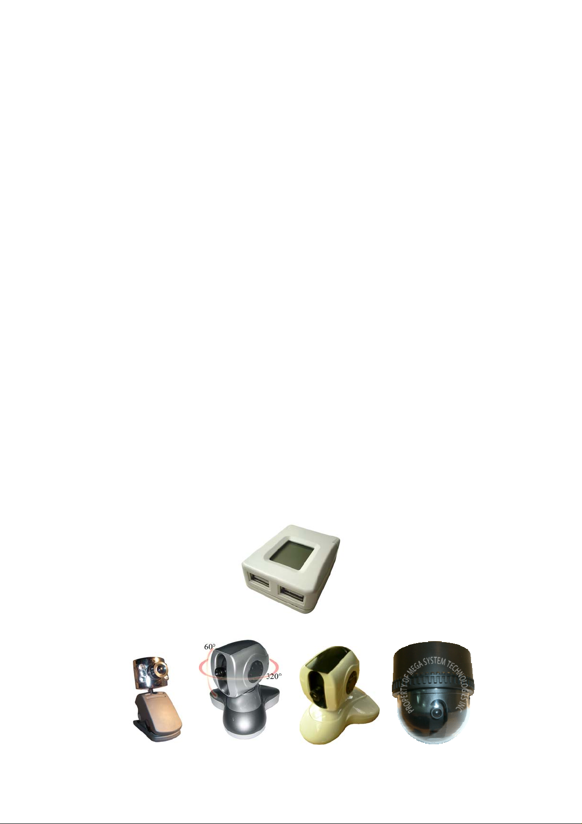
Section 2. WebCAM as a Remote Surveillance System
Once WebCAM is installed, the user can check any of the connected PC cameras
using a standard web browser. The user can monitor and control these cameras
simply by entering the IP address shown on the LCD into a Browser.
WebCAM - user manual -1-
Chapter 1: Introduction
Fig.1 WebCAM Network Diagram
Section 3. Package Contents
WebCAM package contain the following items;
1. WebCAM server.
2. USB Camera.
3. Quick Installation Guide.
4. Utility CD containing;
a. Utility: to configure IP address, update the firmware, etc.
b. MultiMonitor: to monitor multiple WebCAM cameras.
c. Time Server: Time adjustment utility.
d. Adobe Acrobat 5.0 Reader.
e. WebCAM User Manual, and
f. Camera Windows Driver.
5. Slim Ethernet cable.
6. Power adaptor.
WebCAM - user manual -2-
Chapter 1: Introduction
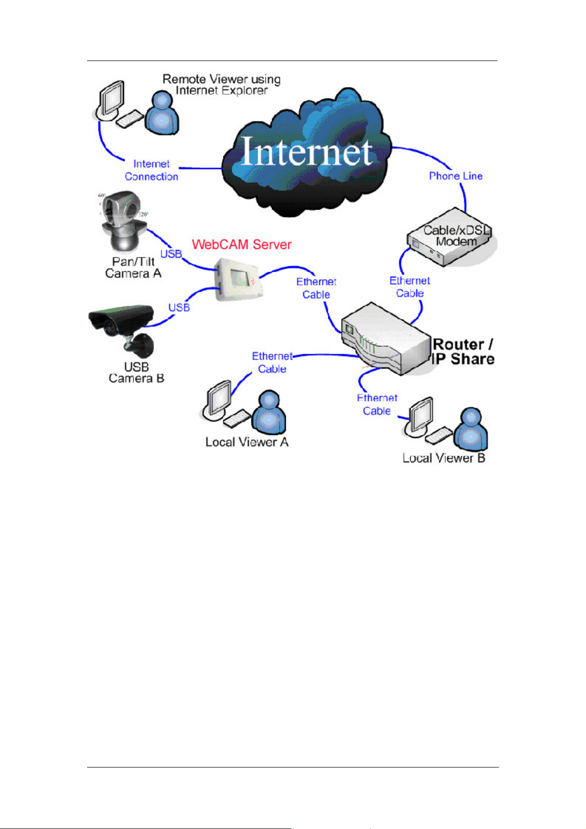
Fig.2 WebCAM Front and Back view
LED Status Indicators on WebCAM
Light color Signal definition Condition description
Green Power state On: Normal power
Red Error Condition Flashing: Error condition occurred
Orange Logon state
On: When there is user logon and
receive the image.
Yellow USB data activity
Flashing: When data is being
transmitted / received.
Fig.3 WebCAM Status LED Indicator
Light indicators on WebCAM LAN Port LED
Light color Condition description
Green
When On: Internet speed is at 100M
When flashing: Data transmitting/receiving
Yellow
On: Internet correspond speed is 10M
Flash: Data transmitting/receiving
Fig.4 WebCAM LAN LED Indicators
Fig.5 WebCAM LCD displayed info
WebCAM - user manual -3-
Chapter 2: Hardware Setup
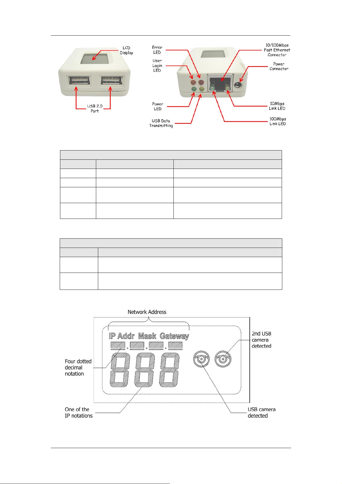
Chapter 2: Hardware Installation
The following details the hardware installation procedure for WebCAM IP camera.
Step 1:
Connect the PC camera into the USB
port of WebCAM.
Step 2:
Connect the WebCAM to LAN by using
the Ethernet UTP port.
Step 3:
Connect DC power adapter output into
WebCAM socket, and plug the DC
power input into the wall socket
Step 4:
Wait a moment and the LCD will
display the IP Address, Subnet and
Gateway. Use a Browser to log into
WebCAM Web Interface
The
icon on the LCD shows that
a USB camera is connected.
The LCD display shows that two USB
cameras are attached to the WebCAM.
WebCAM - user manual -4-
Chapter 3: Web Interface
Chapter 3: Web Interface
Section 1. Introduction
WebCAM is designed to work without having to install any software. All the
necessary functions are built-into the unit.
1. Once you have finished the hardware setup shown in Chapter 2, note down the IP
address shown on the LCD
2. On a PC (located in the same LAN), open a Web Brower (eg.: Internet Explorer,
Netscape, Mozilla Firefox or Opera)
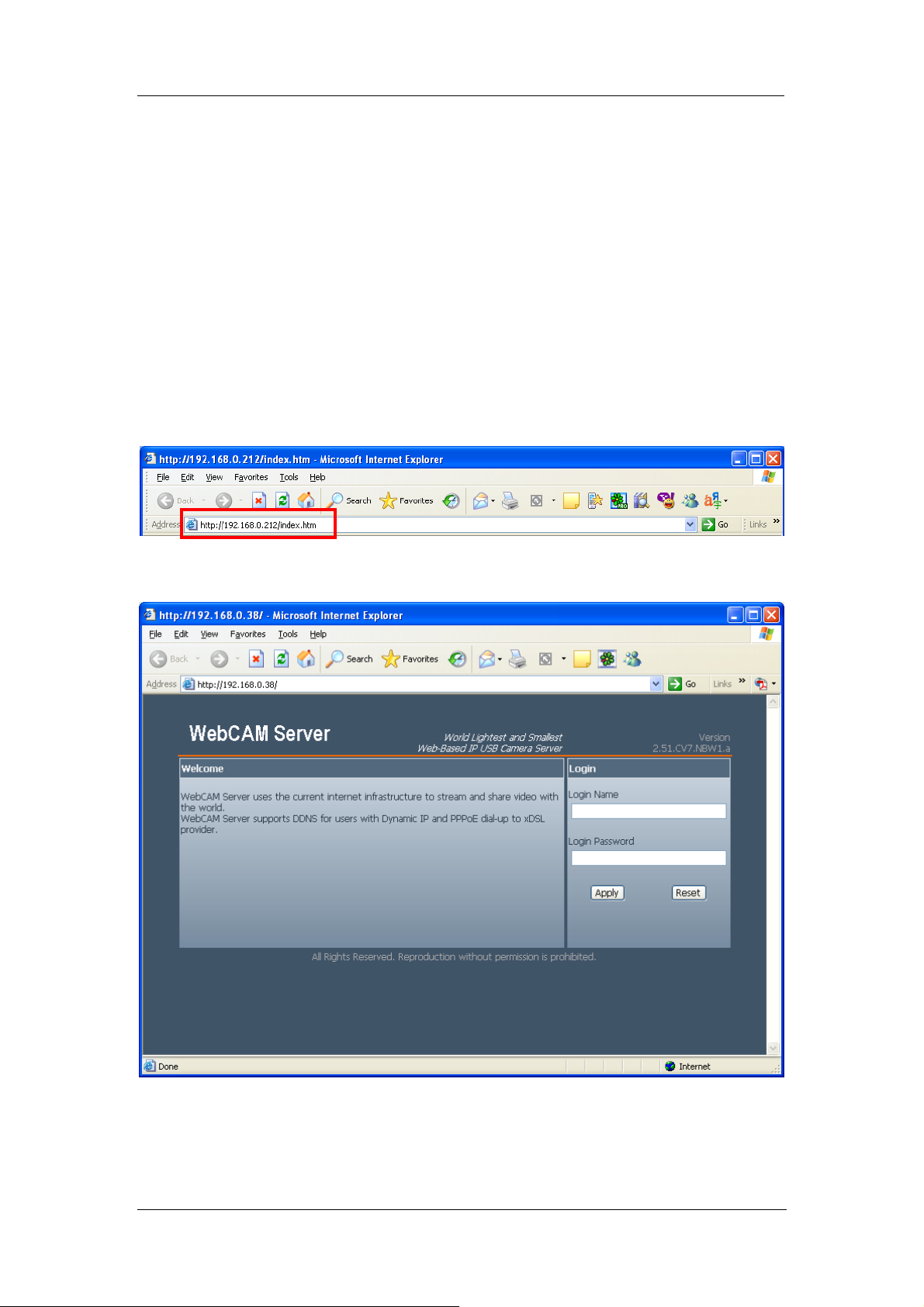
3. Enter the IP Address as shown on the WebCAM LCD display and press ENTER
Fig.6 Enter WebCAM IP address
4. A login screen will appear. Click Apply to login.
Fig.7 WebCAM Login screen
WebCAM - user manual -5-
Chapter 3: Web Interface
Section 2. Using the Web Interface
The WebCAM webpage main menu is divided into two sections. The selection menu
on the left and display menu on the right. The selection menu consists of the
following options:
2.1 View Video
2.2 Information
2.3 Basic Settings
2.4 Advanced Settings
Fig.8 WebCAM Main Menu
When using WebCAM for the first time, check the following settings;
a. Basic Settings Camera Settings Anti Flicker Check that this is set to
the correct lighting frequency. Change this to Outdoor if you intend to point the
camera outside. Click Apply to save the configuration.
b. Manually adjust the camera lens for best results.
WebCAM - user manual -6-
Chapter 3: Web Interface
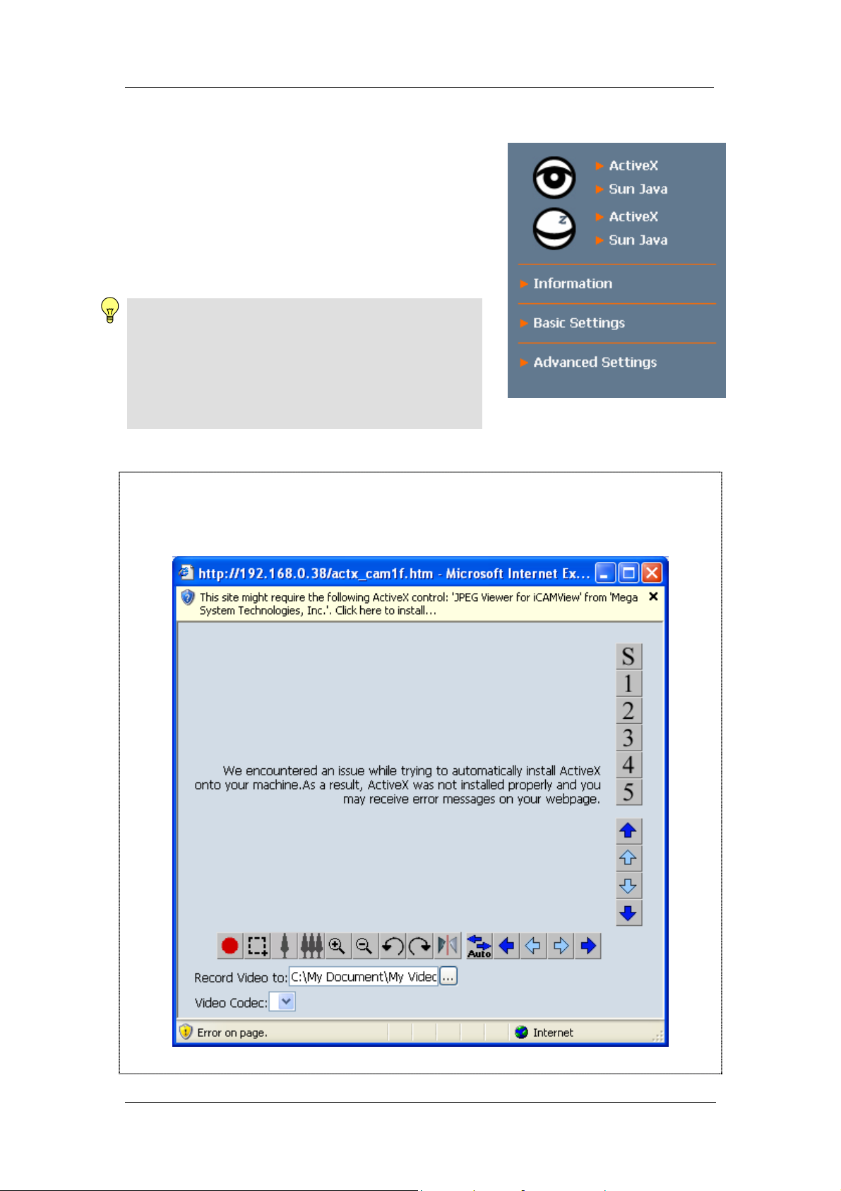
2.1 To View Video
To view video from the connected camera, click on
either ActiveX or Sun Java. Choose either Camera
A or B to view the video.
By default the first USB camera connected to
WebCAM will be Camera A
Note:
ActiveX can only function in Windows platform and a
plug-in has to be installed on the client's computer. I
f
this cannot be installed you will have to use Sun Java
to view the video feed. Users who are not using
Windows based Operating System to view the video
feed by clicking Sun Java.
Using ActiveX Controls:
When using ActiveX for the first time, Windows will ask you to download the ActiveX
Controls.
Click the top bar to download and install the appropriate ActiveX controls.
WebCAM - user manual -7-
Chapter 3: Web Interface
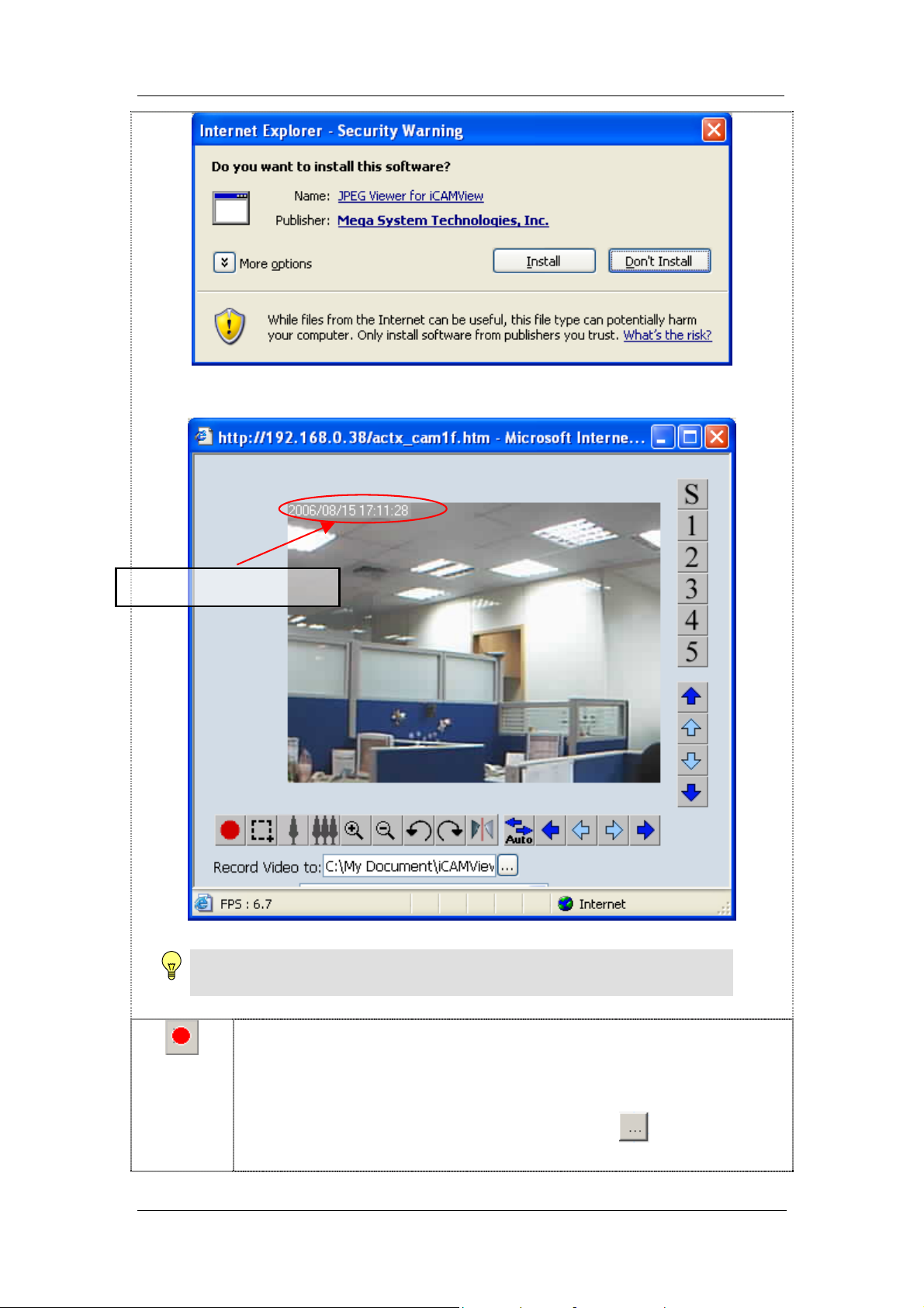
Once installed, the video will stream.
Show current date & time
Click the record button to start video recording.
The default directory is; C:\Windows\Temp\
The video will be saved in the following format;
CMV20060710123058.avi [CMV] [yyyy] [mm] [dd] [ttmmss].avi
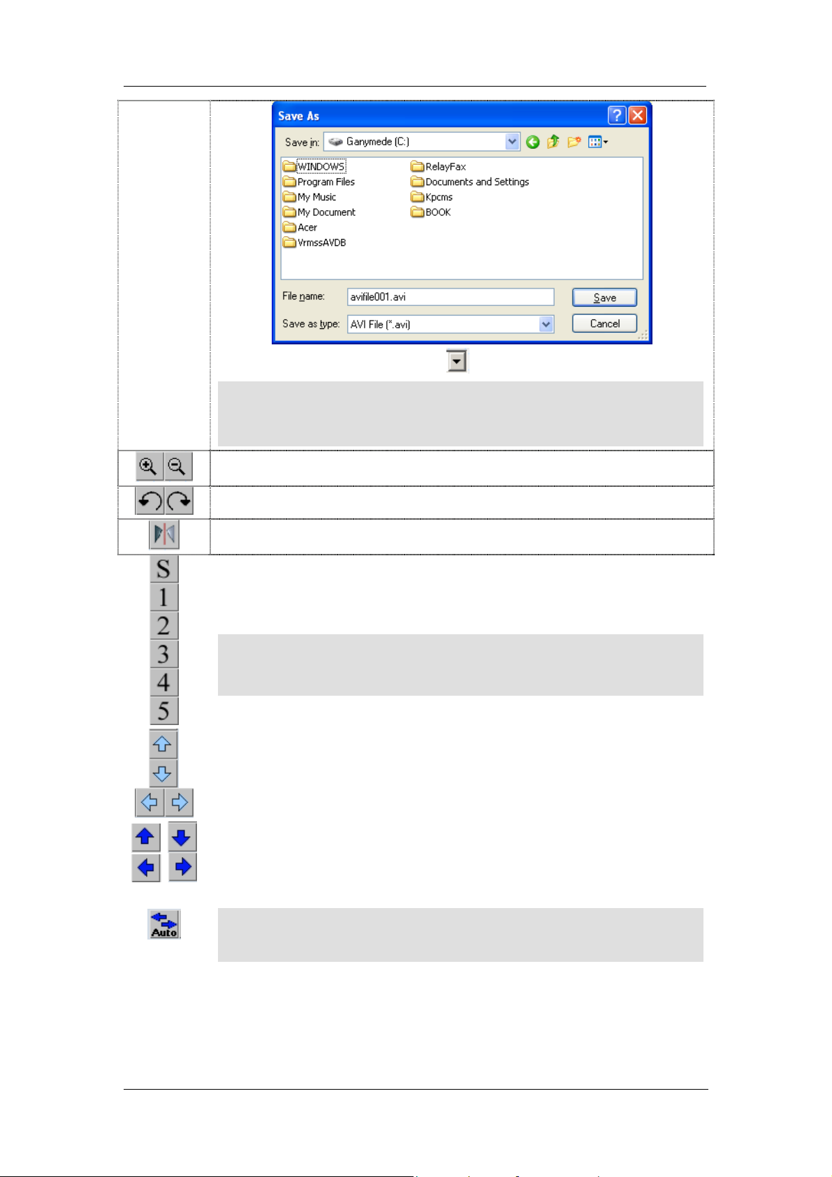
To change the saved location and filename. Click
and the Save As
window will pop up. Choose an alternate location or filename.
Note:
Make sure to adjust the USB camera lens for best picture quality.
WebCAM - user manual -8-
Chapter 3: Web Interface
To change Video Codec, click Click Save to confirm changes.
Digital Zoom In, Digital Zoom Out
Rotate Left, Rotate Right
Flip the image vertically.
HotSpot icon. Each item corresponds to HotSpot location set in Basic
Setting Patrol Settings Hotspot Setting. Click to jump to the
pre-set location.
Click S to recalibrate and center the camera.
Directional Tool. Click to move the camera 1 degree in the direction
of the arrow.
Directional Tool. Click to move the camera 5 degrees in the direction
of the arrow.
Auto Patrol icon. Click to enable auto patrolling.
Note: The availability of Codec depends on weather the individual user
has it installed on the PC or not. Download and install Windows Media
Player 10 to enable MPEG4 codec.
Note:
These icons will not show if you do not have either, (1) a CM03a Pan Tilt
camera, (2) administrator permission or (3) operator permission.
Note:
If the account permission is Viewer, then the HotSpot icon, Directional
WebCAM - user manual -9-
Chapter 3: Web Interface
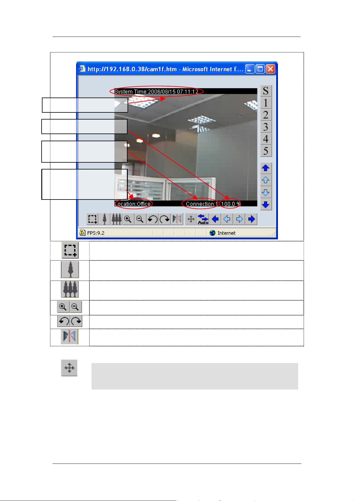
Using Sun Java Controls:
Once you click on Sun Java the following pop-up window will appear.
Click this to Marquee an area and zoom into that area.
Click this to reduce the image resolution.
Click this to increase the image’s resolution.
Click to digitally zoom in or out.
Click to rotate the image.
Flip the image vertically.
Click this to bring up the on screen PanTilt Controls. Click within the full
pan-tilt range of the camera and it will jump to the location.
Shows the number of
viewers for this camera..
Show zoom level (in %)
Show current time & date
Show location as set in
Advanced System
SNMP settings
Note:
This icon will not show if you do not have either , (1) CM03a Pan Tilt camera,
(2) administrator permission or (3) operator permission.
WebCAM - user manual -10-
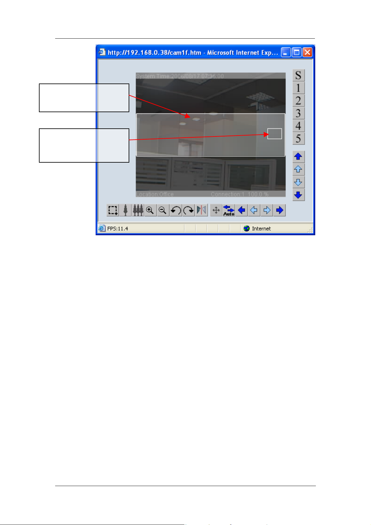
Chapter 3: Web Interface
This indicates the full
pan-tilt range of the USB
Camera.
This is the area and
position the camera is
currently showing.
WebCAM - user manual -11-

Chapter 3: Web Interface
2.2 Information
The Information tab contains the following subsections;
2.2.1 System Status,
2.2.2 Current Connections, and
2.2.3 Event Log.
2.2.1 System Status
This webpage displays all the information relating to WebCAM. This page is
viewable by viewers of all permission levels.
i. System Information
This section shows general hardware information such as the Hardware and
Firmware Version, the serial number, current / local System Time, the system
name, contact, location and uptime.
ii. Network Status
This section shows the network information. The MAC Address is unique to
each WebCAM system.
iii. Camera A / B Information
This section shows the Vendor ID, Product ID and Sensor type used by the
camera. These information are essential in determining if the 3
rd
party USB
camera is WebCAM compatible. Check with your vendor for compatibility.
Fig.9 WebCAM System Status page
WebCAM - user manual -12-
Chapter 3: Web Interface
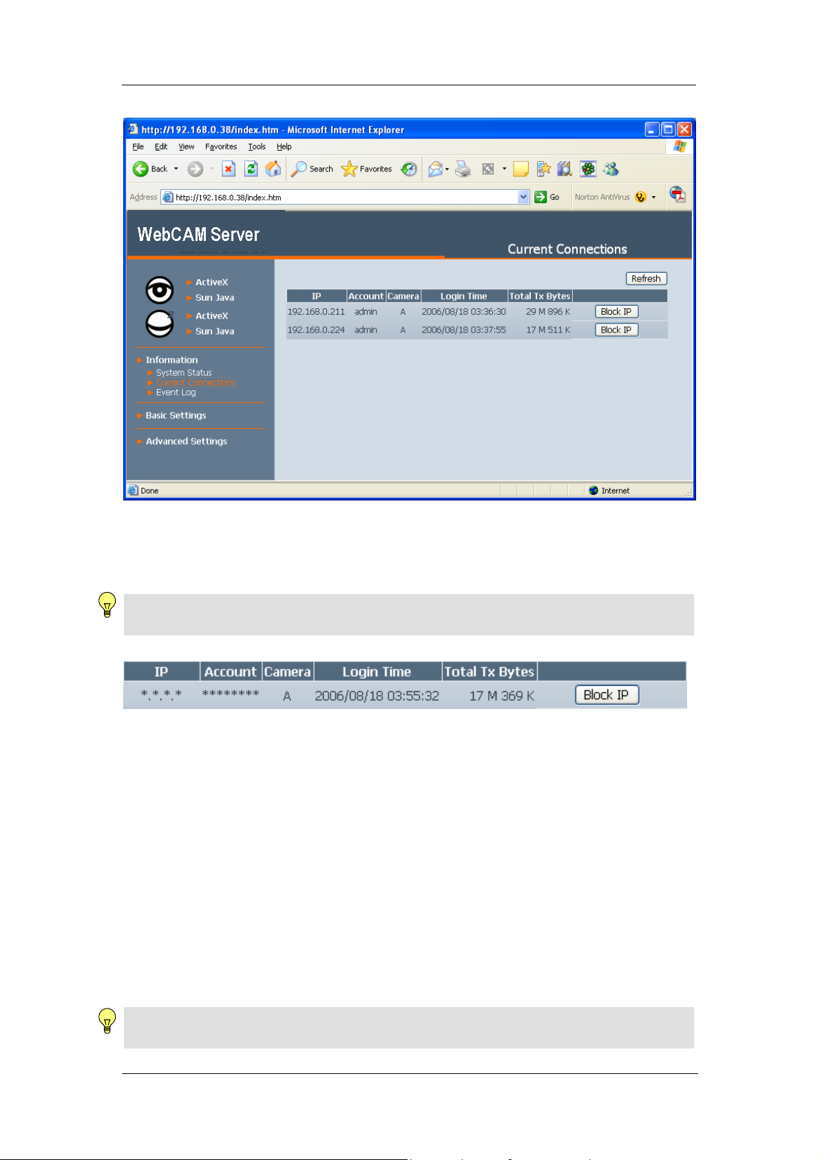
2.2.2 Current Connections
Fig.10 WebCAM Current Connections
The Current Connections page shows all the users currently viewing either Camera
A or Camera B (First icon denotes Camera A). It also lists the login time and total
bytes received.
Note: Administrator privilege is required to view and use Block IP. Otherwise, the IP
and Account details will be hidden and Block IP function disabled.
Fig.11 WebCAM Current Connections: Operator Permission
Click Block IP to block or disable the account of any errant viewer.
To unblock the IP goto Basic Settings Account Settings Blocked IP List and
delete the blocked IP Address from the Blocked IP List.
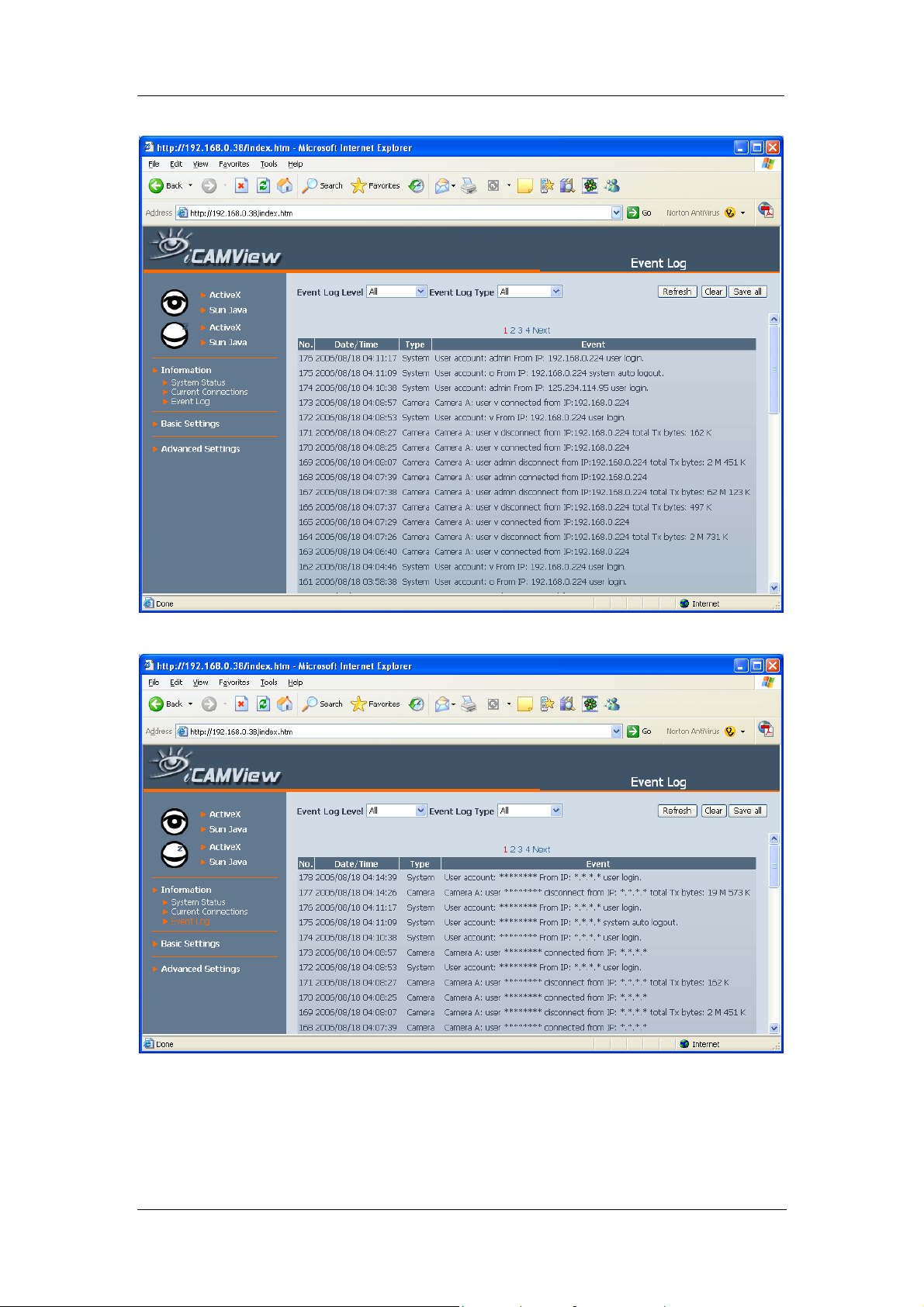
2.2.3 Event Log
This section will keep a record of all events that occurred in WebCAM. The user can
Refresh, Clear or Save the log file. There is also an option to sort the logs according
to “Level” or “Type”. WebCAM can log up to 2,000 events.
Once the number of events has reached the maximum limit, the oldest event will be
removed for each new event logged.
Note: If you do not have Administrator privilege, the User Name and IP Address will be
hidden. Example: Camera A: user ******** connected from IP: *.*.*.*
WebCAM - user manual -13-
Chapter 3: Web Interface
Fig.12 WebCAM Event Log: Administrator privilege.
Fig.13 WebCAM Event Log: Operator privilege.
WebCAM - user manual -14-
Chapter 3: Web Interface
2.3 Basic Settings
The following option allows the user to customize their unit.
2.3.1 Camera Settings
2.3.2 Patrol Settings
2.3.3 Network
2.3.4 Account Settings
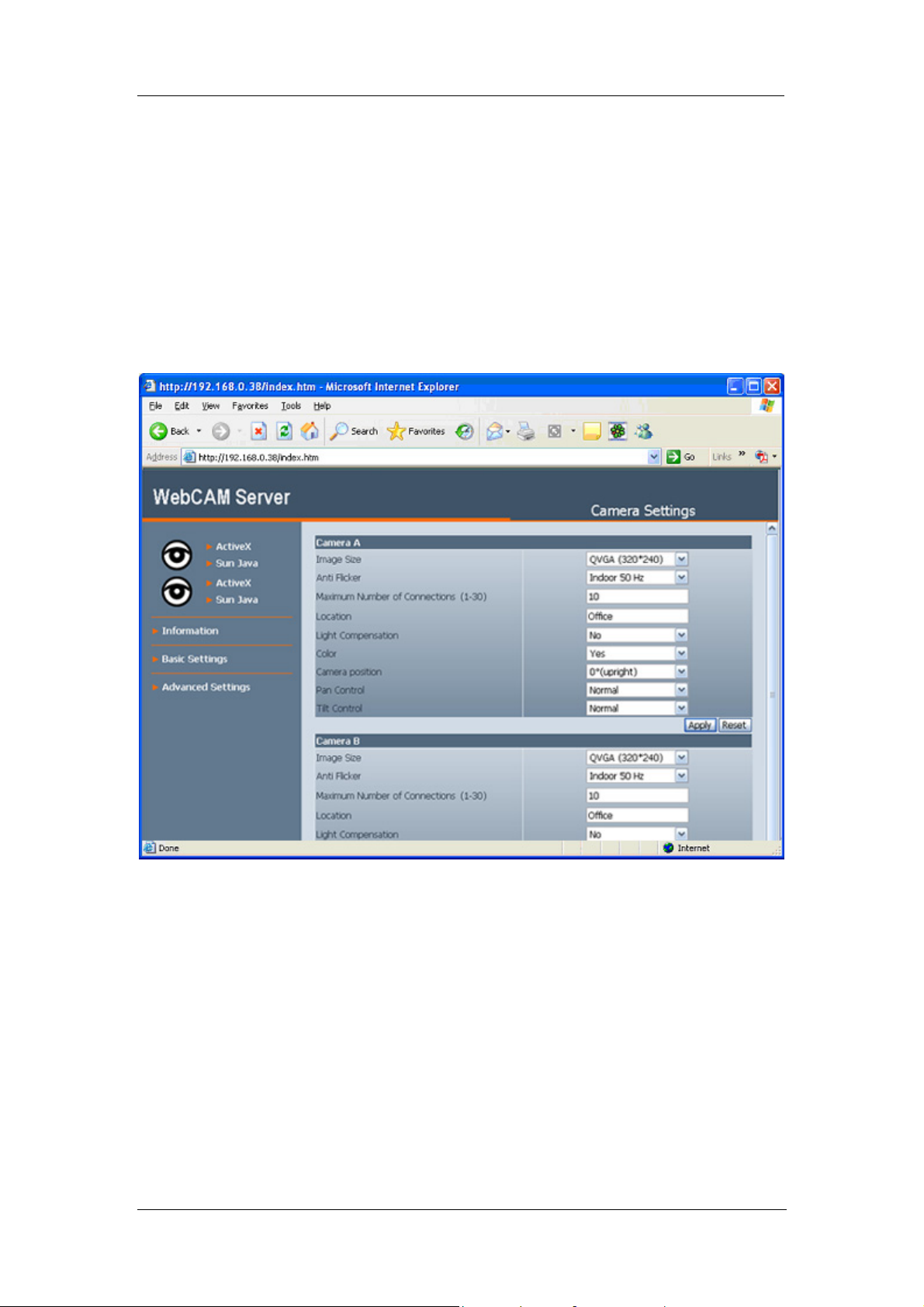
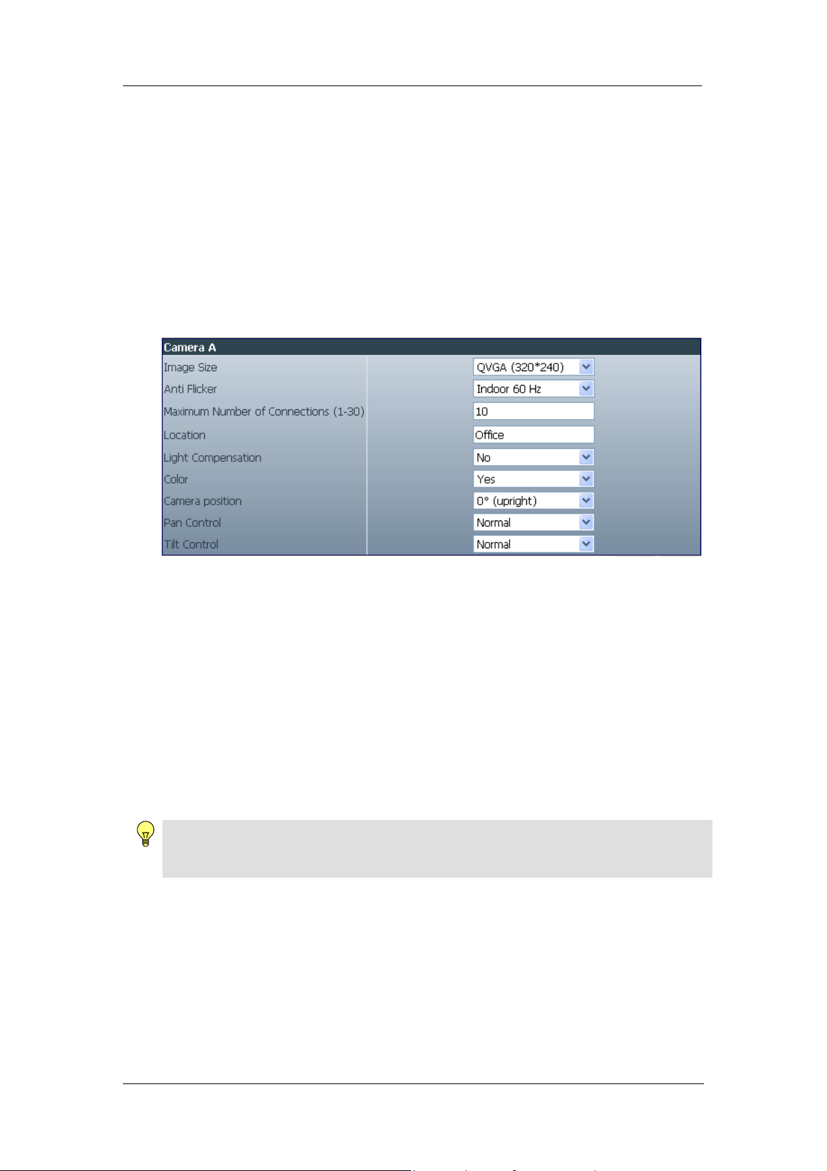
2.3.1 Camera Settings
Use this section to set up the USB camera.
i. Setting up Camera A (or Camera B)
Fig.14 Individual Camera Configuration
Image Size
User can select the following image size;
a. QQVGA (160*120),
b. QCIF (176*144),
c. QVGA (320*240),
d. CIF (352*288),
e. VGA (640*480).
Anti Flicker
Choose between Indoors 50Hz, 60Hz or Outdoors. For best results when
directing the camera to bright sources / windows, select Outdoors.
Note:
If you do not choose the right frequency, the image will flicker or lines will appear on the
images.
Maximum Number of Connections (1-30)
Use this to limit the total number of users that can view this camera at the same
time.
Location
Enter a suitable location / name for the camera.
Light Compensation
WebCAM - user manual -15-

Chapter 3: Web Interface
Choose Yes and WebCAM will increase the lighting of the image. This is useful
when monitoring indoors.
Choose No if you do not want WebCAM to compensate for bright indoor lighting
and view the images as is.
Color
Choose Yes for color and No for black and white display. Black and White
display results in slightly faster FPS (Frames Per Second) video.
Camera Position
Use this option to right the image when WebCAM is installed on the ceiling or
wall. Select either; 0 degree (upright), 90, 180 (upside down), or 270 degree.
Pan Control
Use this function to reverse the Pan direction.
Tilt Control
Use this function to reverse the Tilt controls, if necessary.
Note:
Always click Apply to save any changes made. Otherwise, the changes will be lost.
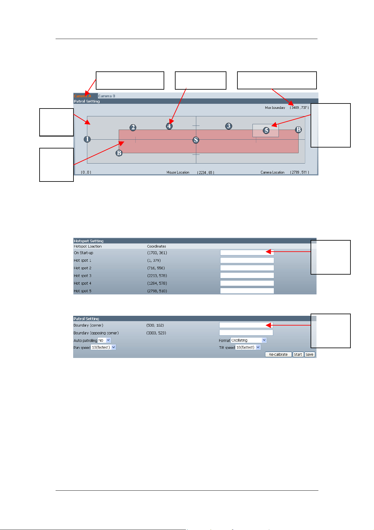
2.3.2 Patrol Settings
This option is only available if a CM03a USB PanTilt Camera is used. Otherwise the
function remains hidden.
i. Patrol Setting
WebCAM - user manual -16-
Chapter 3: Web Interface
This section allows the user to define hotspots, required patrol boundary, and
see where the current camera position.
Fig.15 WebCAM Patrol Setting / Controls
User
defined
Pan Tilt
boundar
y
Maximum boundary (x,y)
of the Pan Tilt camera
Click to select which
camera to control.
User defined
hot spot bubble.
Current
camera
position
and view
area.
Show ful
Pan Tilt
range.
HotSpot Settings
This part shows the hotspot coordinates and the Administrator can give each
location a name. Click and hold on the Hotspot bubble in the above patrol
control to re-define the coordinates.
Enter a
name for
the selected
hots
p
ot
Patrol Setting
Enter a
name for
the selected
hots
p
ot
Boundary
This defines the camera patrol boundary. Click and hold on either one of the
two boundary bubble to redefine the boundary.
Auto Patrolling
Select Yes to start auto patrolling function.
Select No to stop the patrolling function.
Format
Choose from 5 different patrolling formats;
a. Oscillating – The camera will pan and tilt at the same time within the user
defined boundary. Camera will oscillate from left to right and back.
WebCAM - user manual -17-

Chapter 3: Web Interface
b. Square – The camera wi ll patrol along the user defined boundary in a clock
wise manner.
c. Pan only – The camera will perform Pan function only.
d. Tilt only – The camera will perform tilt function only.
e. In sequence (1-5) – The camera will jump to each Hotspot location in
sequence and wait for 10 seconds in each spot.
Pan speed / Tilt Speed
Use this to define the Pan and Tilt speed. By default this is set to 10, the
fastest setting. The administrator can further customize by choosing different
Pan / Tilt speed.
2.3.3 Network
This option determines WebCAM Network settings.
ii. IP Address
By default, the IP address acquisition is set to using DHCP.
Fig.16 WebCAM IP Address Settings
IP Address
This determines WebCAM LAN IP address.
Subnet Mask
Enter WebCAM Subnet Mask. The value is normally 255.255.255.0
Gateway
This item is to set WebCAM Gateway.
To learn more about the above, see Appendix C: IP address, Subnet and
Gateway
Obtain an IP address
This allows the user to choose either to set WebCAM LAN IP address; manually,
using DHCP (default) or using Bootp protocol.
Note:
Click Apply to confirm. WebCAM will reboot. You MUST manu ally enter the NEW
IP address in your Browser in order to open the Web Interface.
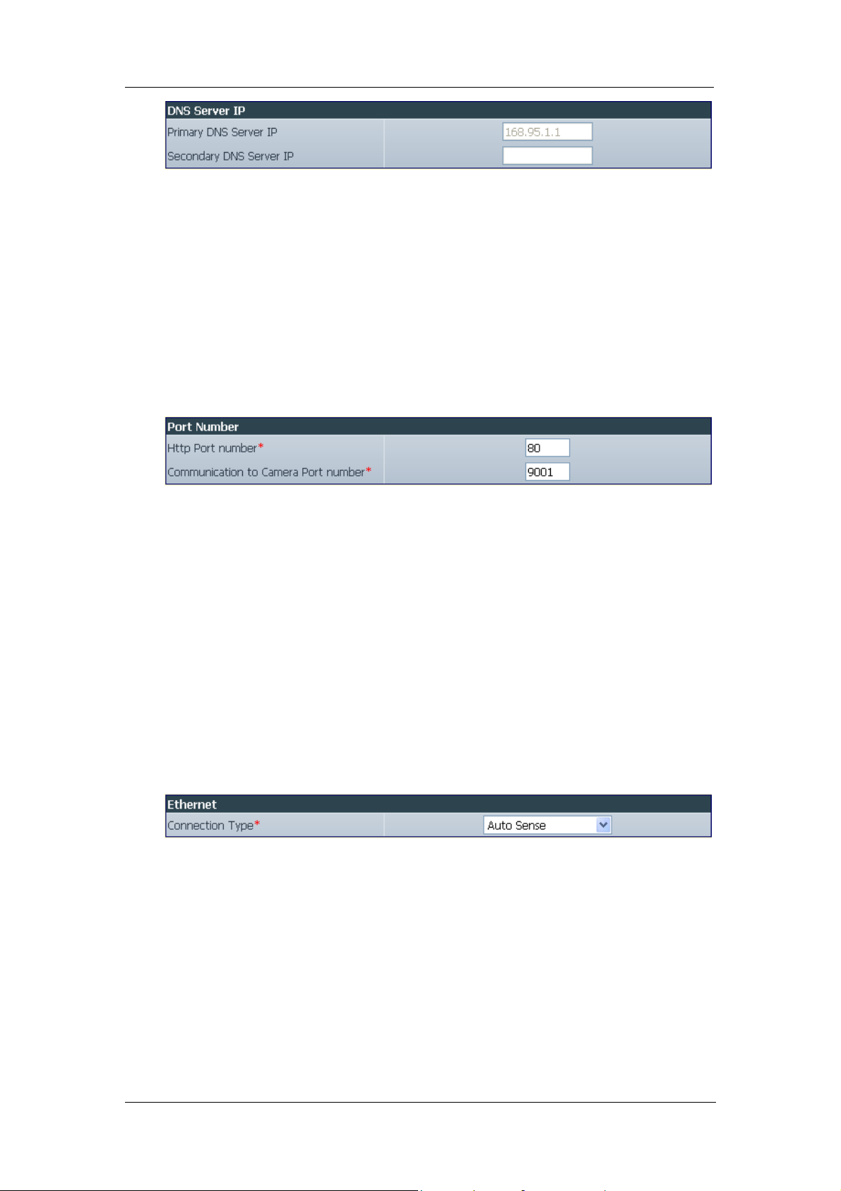
iii. DNS Server IP
WebCAM - user manual -18-
Chapter 3: Web Interface
Fig.17 WebCAM DNS Server IP
Primary DNS Server IP
This item sets WebCAM primary DNS Server IP address. This is the default
DNS and cannot be edited.
Secondary DNS Server IP
Use this to set WebCAM Secondary DNS Server IP address. WebCAM will
use the Secondary DNS Server IP address if the Primary DNS Server IP
address is not working.
iv. Port Number
Fig.18 WebCAM Port Settings
HTTP Port Number
This determines the LAN port from which the webpage (using HTTP protocol) is
accessible thru your Router. By default the LAN port number is 80.
If this port is changed, say to 82, then http://xxx.xxx.xxx.xxx:82 (where
xxx.xxx.xxx.xxx is WebCAM LAN IP address as shown on the LCD) must be
used in order to access WebCAM web interface in LAN.
Communication to Camera Port Number
This determines the LAN port from which the video image (using UDP protocol)
is streamed thru your Router. By default the LAN port number is 9001.
v. Ethernet
Fig.19 WebCAM Ethernet Settings
Connection Type
This sets WebCAM communication speed. By default, it is set to Auto Sense.
WebCAM will reboot, if this setting is changed.
i. WebCAM Dynamic DNS
This free service allows the user to alias a dynamic IP address to a static
hostname. No matter how many times your ISP change the IP, you will be able
to locate WebCAM.
WebCAM - user manual -19-
Chapter 3: Web Interface
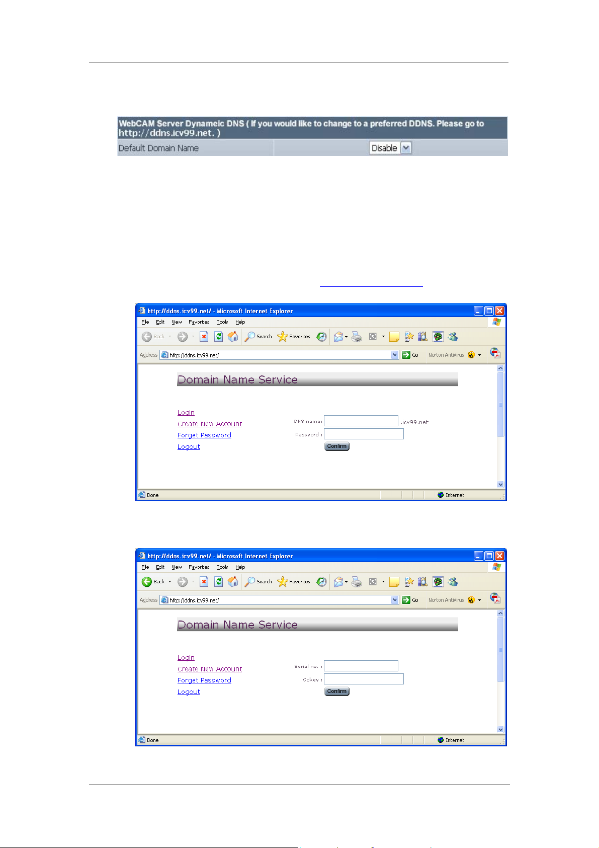
Each WebCAM unit is shipped with a default domain name ***.icv99.net, where
*** is the unique 10 digit serial number located at the back of WebCAM.
Fig.20 WebCAM Default Dynamic DNS
Use Default Domain Name
Each unit of WebCAM is shipped with a default Domain Name. To activate this
feature;
1. Select Enable from the drop-down menu and click Apply.
2. Activate the feature by logging on to
http://ddns.iCV99.net and click Create
New Account.
3. Register by entering the Serial Number and Master Passwo rd (as shown
at the back of WebCAM) and click Confirm.
WebCAM - user manual -20-
Chapter 3: Web Interface
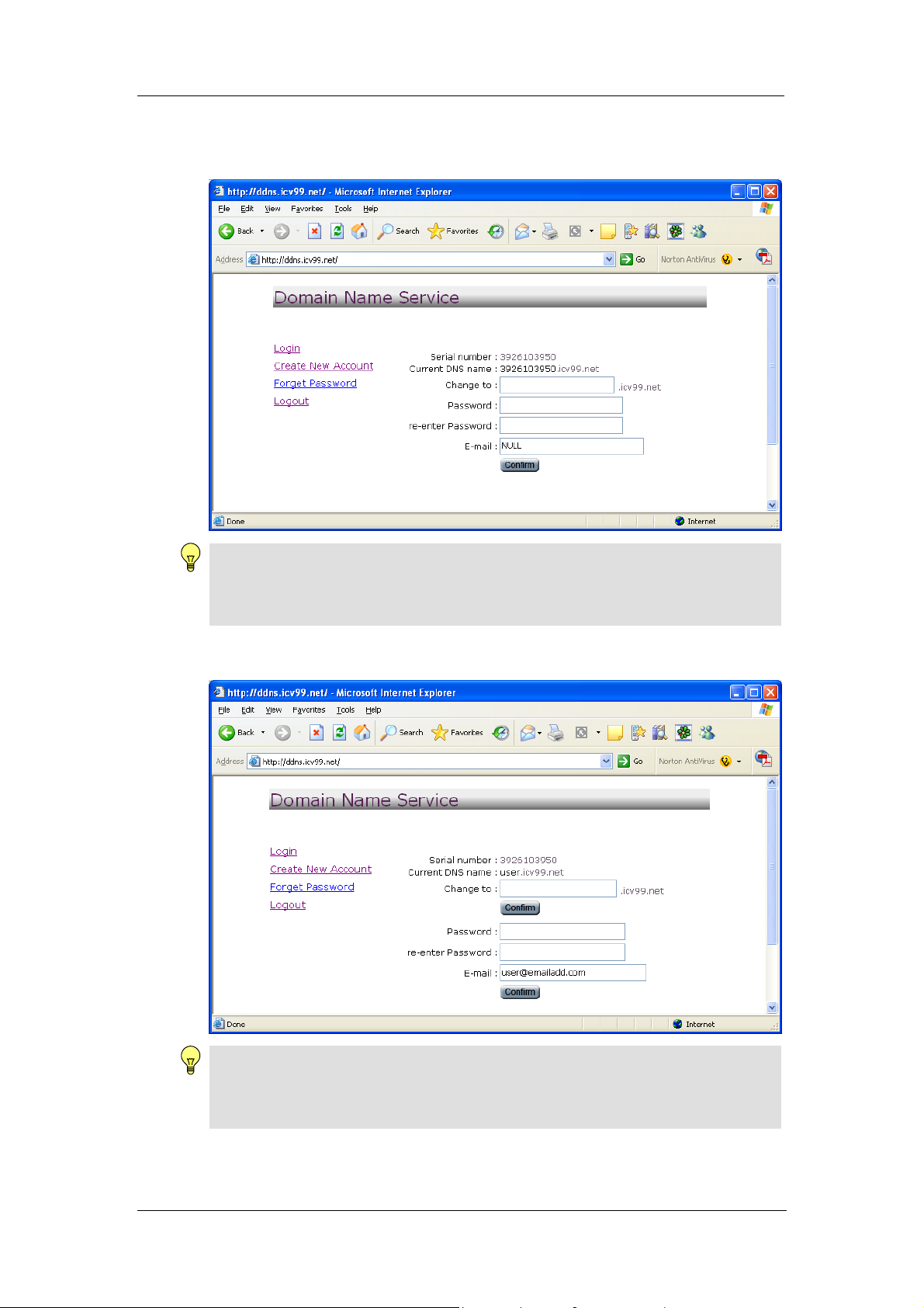
4. Once registered, user can change either, the default domain name, DNS
password or Email address. Click Confirm to save changes.
Note:
Enter a valid Email address. In the event you have forgotten the password to
your DNS account, a new password will be sent to this email address upon
request.
5. Registration complete. Account details shown as follows;
Note:
In order to view from remote, Port Forwarding must be configured at your Router.
See Appendix A for more information.
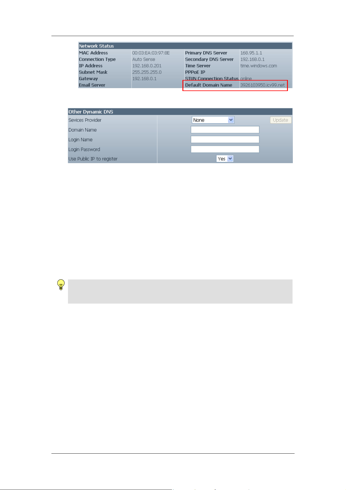
6. With the registration complete, the following additional information can be
seen under Information System Status Network Status.
WebCAM - user manual -21-
Chapter 3: Web Interface
ii. Other Dynamic DNS
Fig.21 Dynamic DNS from other Service Providers
Service Provider
In addition to http://ddns.iCV99.net, WebCAM can be configured to register with
other Dynamic DNS providers. The following free DDNS service providers are
supported;
• dhs.org
• dyndns.org
• myddns.com
• zive.org
• 88IP.cn
• myneteyes.com
Click Update to get latest list of Service Providers.
Note:
The number of available DDNS service providers depends on the region Web CAM is
purchased.
In general, to register a Domain Name;
a. Go to the DDNS provider website listed above.
b. Register a new user account and password with the DDNS provider.
c. Choose a Domain Name to point to your current Dynamic IP
d. Enter information obtained in (b) and (c) into WebCAM DDNS fields.
Domain Name
This is the Domain Name you have created from the above selected DDNS
provider.
Login Name
This is the Login / Account name that you have created with the selected DDNS
provider.
Login Password
Enter the Password you have assigned to your DDNS Account.
WebCAM - user manual -22-
Chapter 3: Web Interface
Use Public IP to register
Choose Yes to ensure that WebCAM uses the WAN / Public IP to register with
the selected DDNS server.
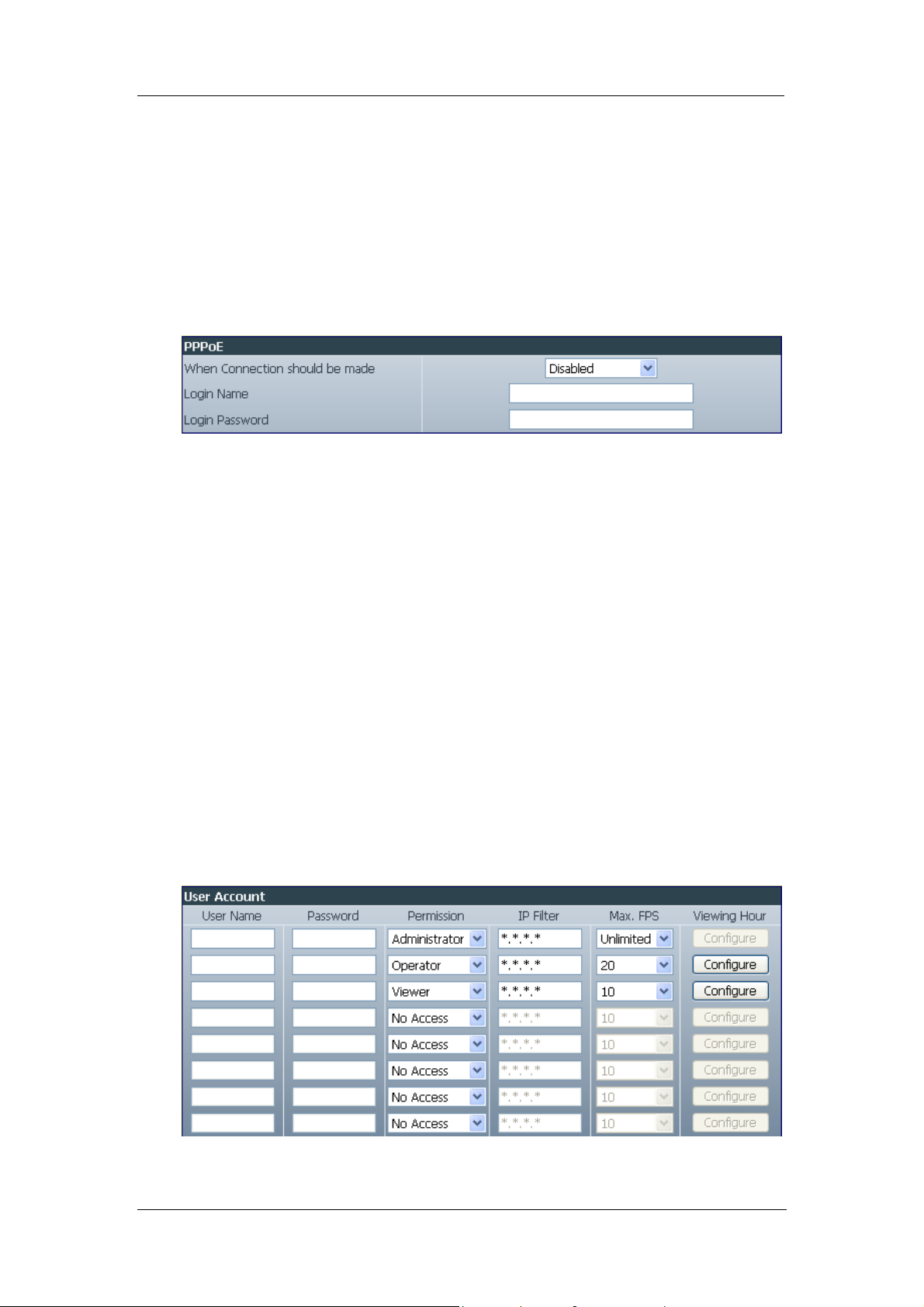
iii. PPPoE
Use this option to allow WebCAM to connect to the internet directly using your
xDSL modem. Once set-up, WebCAM will connect directly to the Internet
without going through a router. The LCD will display the current WAN / Public
IP instead of the LAN IP Address.
Fig.22 WebCAM PPPoE setting
When Connection should be made
Disabled : Default setting.
Connect always : WebCAM will automatically dial up and maintain
continuous connection.
Login Name
Enter the login name assigned by your ISP.
Login Password
Enter the password assigned by your ISP.
2.3.3 Account Settings
This webpage allows you to set up to Eight (8) different user accounts with different
access permission level to WebCAM. This section can only be edited by an
administrator.
i. User Account
Fig.23 User Account Settings
WebCAM - user manual -23-

Chapter 3: Web Interface
User Name
Assign a User Name / Account. The administrator can set up to 32 case
sensitive character names.
Password
Assign a password to the account. The administrator can set up to 32 case
sensitive passwords.
Permission
This sets the access level to individual user accounts.
Administrator: An Administrator has full access including write permission
to all menus and sub-sections. Only an Administrator can
see the User Name and IP address fields or set the camera
access Permit Hours to Operator or Viewer accounts.
Operator: The user can access all menus, but does not have
permission to amend the data fields.
Viewer: The user can only view camera within the time specified in
Permit Hours. The user does not have write permission,
can only view Camera A/B and read the Information
section.
No Access: This disables either of the above two permission levels given
to a user.
Note:
An Administrator account must be set before setting up either an Operator or
Viewer account.
IP Filter
Use this feature to ensure that the user only login from the IP address specified
here. Leave it as *.*.*.* to allow the user to login from any place.
Example:
Entering 192.168.1.* will only allow User to access from 192.168.1.xxx IP
addresses.
Max FPS
This allows the Administrator to limit the bandwidth allocated to each account.
The Administrator can set a figure of 1 to Unlimited FPS (“frames per second”).
Viewing Hours
When the Permission level is set to either Operator or Viewer, the Administrator
can set the time to which the camera can be viewed.
WebCAM - user manual -24-
Chapter 3: Web Interface
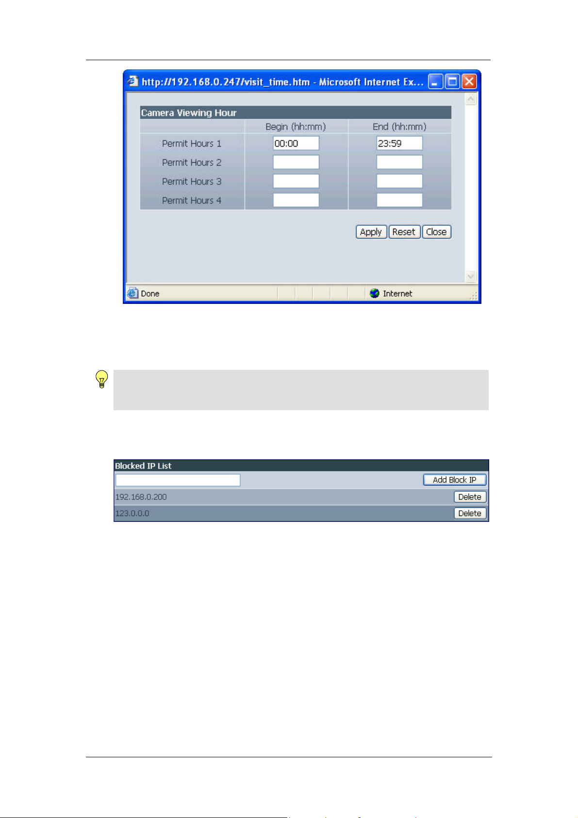
Fig.24 WebCAM Permit Hours Configuration
Click Configure to set the hours. The Administrator can set up to 4 different
Permit Hours (in 24hr format). Click Apply to save. Click Close to exit
without saving.
Note:
The Reset button only revert the fields to initial values prior to any changes being
made. If Apply has been clicked, it will not undo the changes.
ii. Block IP address
Fig.25 Blocking LAN IP address
Blocked IP List
This allows the Administrator to block specific LAN IP address from accessing
WebCAM. Enter the IP address in dotted decimal notation and click Add
Block IP. The blocked LAN IP address will be listed at the bottom.
Click Delete to remove it from the list.
WebCAM - user manual -25-
Chapter 3: Web Interface
2.4 Advanced Settings
This section allows the Administrator to set up some of the features available in the
server.
2.4.1 Event Notification
2.4.2 Motion Detection
2.4.3 Image Recording
2.4.4 Email / FTP
2.4.5 System Settings
2.4.6 Image Server
2.4.7 Language
2.4.8 About
2.4.1 Event Notification
This section determines the type of event that will be included if an email notification is
sent by WebCAM.
Note:
Administrator privilege is required to configure this section.
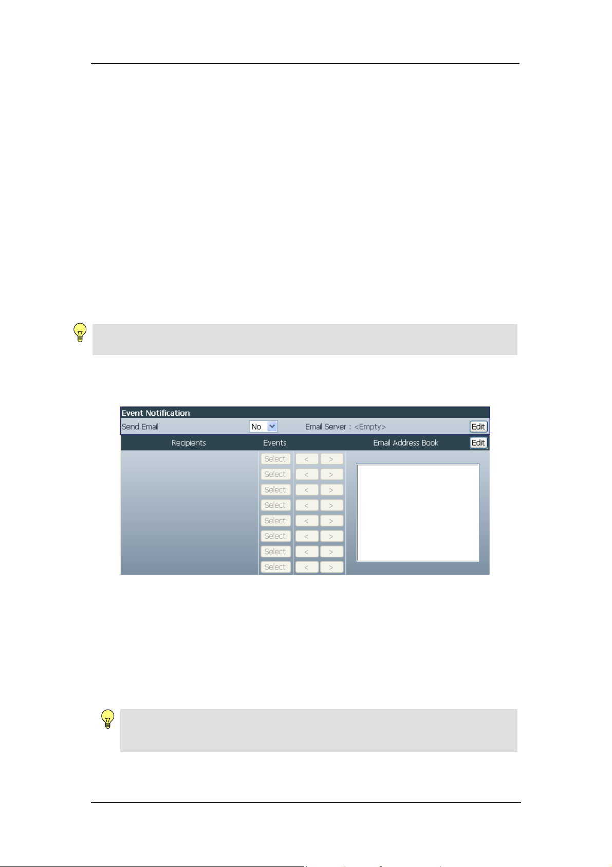
i. Event Notification
A total of 8 email recipients can be assigned to receive notification.
Fig.26 WebCAM Event Notification Page
Send Email
Select Yes to activate this feature. Default is No.
Email Server
A valid Email Server, User name and password must be setup for this feature to
work. If this has not been setup, click Edit and to go to Email / FTP setup page.
(see Section 2.4.4)
Note:
Email function can only work using standard Email Server and not Web based Email
Server, such as yahoo.com
Email Address Book
WebCAM - user manual -26-

Chapter 3: Web Interface
The available Email addresses are listed here. See Section 2.4.4 on how to
enter an Email address to the Address Book.
To add an email address click Edit. WebCAM will ask you to save your
configuration prior to leaving this page.
Recipients
Up to 8 valid email accounts can receive Email Notification. To add an email
address to the recipient list, click <. To remove, click >.
Note:
Only Email addresses that are listed in the Email Address Book can be added.
Events
This section determines the events that the selected recipient/s will receive by
email. There are three types of events; Information, Warning and Error. Click
Select to select the list of events the recipients will be notified.
By default, all the events are selected but not confirmed. Click Apply to
activate and confirm selection.
Click
to close the window and return to the Event Notification page.
WebCAM - user manual -27-
 Loading...