


 Loading...
3Com Switch 4500 Family
Configuration Guide
Switch 4500 26-Port
Switch 4500 50-Port
Switch 4500 PWR 26-Port
Switch 4500 PWR 50-Port
Product Version: V03.03.00 Manual Version:
6W101-20090811 www.3com.com
3Com Corporation
350 Campus Drive, Marlborough,
MA, USA 01752 3064
Copyright © 2006-2009, 3Com Corporation. All rights reserved. No part of this documentation may be reproduced in any form or by any means or used to make any derivative work (such as translation, transformation, or adaptation) without written permission from 3Com Corporation.
3Com Corporation reserves the right to revise this documentation and to make changes in content from time to time without obligation on the part of 3Com Corporation to provide notification of such revision or change.
3Com Corporation provides this documentation without warranty, term, or condition of any kind, either implied or expressed, including, but not limited to, the implied warranties, terms or conditions of merchantability, satisfactory quality, and fitness for a particular purpose. 3Com may make improvements or changes in the product(s) and/or the program(s) described in this documentation at any time.
If there is any software on removable media described in this documentation, it is furnished under a license agreement included with the product as a separate document, in the hard copy documentation, or on the removable media in a directory file named LICENSE.TXT or !LICENSE.TXT. If you are unable to locate a copy, please contact 3Com and a copy will be provided to you.
UNITED STATES GOVERNMENT LEGEND
If you are a United States government agency, then this documentation and the software described herein are provided to you subject to the following:
All technical data and computer software are commercial in nature and developed solely at private expense. Software is delivered as “Commercial Computer Software” as defined in DFARS 252.227-7014 (June 1995) or as a “commercial item” as defined in FAR 2.101(a) and as such is provided with only such rights as are provided in 3Com’s standard commercial license for the Software. Technical data is provided with limited rights only as provided in DFAR 252.227-7015 (Nov 1995) or FAR 52.227-14 (June 1987), whichever is applicable. You agree not to remove or deface any portion of any legend provided on any licensed program or documentation contained in, or delivered to you in conjunction with, this User Guide.
Unless otherwise indicated, 3Com registered trademarks are registered in the United States and may or may not be registered in other countries.
3Com and the 3Com logo are registered trademarks of 3Com Corporation.
All other company and product names may be trademarks of the respective companies with which they are associated.
ENVIRONMENTAL STATEMENT
It is the policy of 3Com Corporation to be environmentally-friendly in all operations. To uphold our policy, we are committed to:
Establishing environmental performance standards that comply with national legislation and regulations. Conserving energy, materials and natural resources in all operations.
Reducing the waste generated by all operations. Ensuring that all waste conforms to recognized environmental standards. Maximizing the recyclable and reusable content of all products.
Ensuring that all products can be recycled, reused and disposed of safely.
Ensuring that all products are labelled according to recognized environmental standards. Improving our environmental record on a continual basis.
End of Life Statement
3Com processes allow for the recovery, reclamation and safe disposal of all end-of-life electronic components.
Regulated Materials Statement
3Com products do not contain any hazardous or ozone-depleting material.
Environmental Statement about the Documentation
The documentation for this product is printed on paper that comes from sustainable, managed forests; it is fully biodegradable and recyclable, and is completely chlorine-free. The varnish is environmentally-friendly, and the inks are vegetable-based with a low heavy-metal content.
About This Manual
Organization
3Com Switch 4500 Family Configuration Guide is organized as follows:
|
|
Part |
Contents |
|
1 |
Login |
Introduces the ways to log into an Ethernet switch and CLI |
||
related configuration. |
||||
|
|
|
||
|
|
|
||
2 |
Configuration File Management |
Introduces configuration file and the related configuration. |
||
|
|
|
||
3 |
VLAN |
Introduces VLAN and related configuration. |
||
|
|
|
||
4 |
IP Address and Performance |
Introduces IP address and IP performance optimization |
||
Optimization |
related configuration |
|||
|
|
|
||
5 |
Voice VLAN |
Introduces voice VLAN and the related configuration. |
||
|
|
|
||
6 |
Port Basic Configuration |
Introduces port basic configuration. |
||
|
|
|
||
7 |
Link Aggregation |
Introduces link aggregation and the related configuration. |
||
|
|
|
||
8 |
Port Isolation |
Introduces port isolation and the related configuration. |
||
|
|
|
||
9 |
Port Security |
Introduces port security and the related configuration. |
||
|
|
|
||
10 |
DLDP |
Introduces DLDP and the related configuration. |
||
|
|
|
|
|
11 MAC Address Table Management |
Introduces MAC address forwarding table management and |
|||
the related configuration |
||||
|
|
|
|
|
12 |
Auto Detect |
Introduces auto detect function and the related |
||
configuration. |
||||
|
|
|
||
|
|
|
||
13 |
MSTP |
Introduces STP, MSTP, and the related configuration. |
||
|
|
|
|
|
14 |
Routing Protocol |
Introduces static routing protocol, RIP, routing policy, and |
||
the related configuration. |
||||
|
|
|
||
|
|
|
|
|
15 |
Multicast |
Introduces multicast, IGMP snooping, and the related |
||
configuration. |
||||
|
|
|
||
|
|
|
||
16 |
802.1x and System Guard |
Introduces 802.1x and the related configuration. |
||
|
|
|
|
|
17 AAA |
Introduces AAA, RADIUS, EAD, and the related |
|||
configurations. |
||||
|
|
|
||
|
|
|
|
|
18 |
MAC Address Authentication |
Introduces MAC address authentication and the related |
||
configuration. |
||||
|
|
|
||
|
|
|
||
19 |
ARP |
Introduces ARP and the related configuration. |
||
|
|
|
|
|
20 DHCP |
Introduces DHCP relay agent, DHCP Snooping, |
|||
DHCP/BOOTP client, and the related configuration. |
||||
|
|
|
||
|
|
|
||
21 |
ACL |
Introduces ACL and the related configuration. |
||
|
|
|
||
22 |
QoS |
Introduces QoS and the related configuration. |
||
|
|
|
||
23 |
Mirroring |
Introduces mirroring and the related configuration. |
||
|
|
|
||
24 |
XRN Fabric |
Introduces XRN fabric and the related configuration. |
||
|
|
|
||
25 |
Cluster |
Introduces cluster and the related configuration. |
||
|
|
|
||
26 |
PoE-PoE Profile |
Introduces PoE, PoE profile and the related configuration. |
||
|
|
|
|
|
|
|
Part |
|
Contents |
27 |
UDP Helper |
Introduces UDP helper and the related configuration. |
||
|
|
|
|
|
|
28 SNMP-RMON |
|
Introduces the configuration for network management |
|
|
|
through SNMP and RMON |
||
|
|
|
|
|
|
|
|
||
29 |
NTP |
Introduces NTP and the related configuration. |
||
|
|
|
|
|
30 |
SSH |
|
Introduces SSH2.0 and the related configuration. |
|
|
|
|
|
|
31 |
File System Management |
|
Introduces basic configuration for file system management. |
|
|
|
|
|
|
|
32 FTP-SFTP-TFTP |
|
Introduces basic configuration for FTP, SFTP and TFTP, |
|
|
|
and the applications. |
||
|
|
|
|
|
|
|
|
|
|
33 |
Information Center |
|
Introduces information center and the related configuration. |
|
|
|
|
|
|
34 |
System Maintenance and |
|
Introduces system maintenance and debugging. |
|
|
Debugging |
|
||
|
|
|
||
|
|
|
|
|
|
35 VLAN-VPN |
|
Introduces VLAN-VPN, selective QinQ, and the related |
|
|
|
configuration. |
||
|
|
|
|
|
|
|
|
|
|
36 |
Remote-ping |
|
Introduces Remote-ping and the related configuration. |
|
|
|
|
|
|
|
37 IPv6 Management |
|
Introduces IPv6, IPv6 applications, and the related |
|
|
|
configuration. |
||
|
|
|
|
|
|
|
|
|
|
|
38 Access Management |
|
Introduces Access Management and the related |
|
|
|
configuration. |
||
|
|
|
|
|
|
|
|
||
39 |
Appendix |
Lists the acronyms used in this manual |
||
|
|
|
|
|
Conventions
The manual uses the following conventions:
Command conventions
Convention |
Description |
|
|
Boldface |
The keywords of a command line are in Boldface. |
|
|
|
|
|
|
italic |
Command arguments are in italic. |
|
|
|
|
|
|
[ ] |
Items (keywords or arguments) in square brackets [ ] are optional. |
|
|
|
|
||
{ x | y | ... } |
Alternative items are grouped in braces and separated by vertical bars. |
||
One is selected. |
|
|
|
|
|
|
|
|
|
|
|
[ x | y | ... ] |
Optional alternative items are grouped in square |
brackets |
and |
separated by vertical bars. One or none is selected. |
|
|
|
|
|
|
|
|
|
||
{ x | y | ... } * |
Alternative items are grouped in braces and separated by vertical bars. |
||
A minimum of one or a maximum of all can be selected. |
|
|
|
|
|
|
|
|
|
|
|
[ x | y | ... ] * |
Optional alternative items are grouped in square |
brackets |
and |
separated by vertical bars. Many or none can be selected. |
|
||
|
|
||
|
|
||
&<1-n> |
The argument(s) before the ampersand (&) sign can be entered 1 to n |
||
times. |
|
|
|
|
|
|
|
|
|
|
|
# |
A line starting with the # sign is comments. |
|
|
|
|
|
|
GUI conventions
Convention |
|
|
Description |
< > |
|
Button names are inside angle brackets. For example, click <OK>. |
|
|
|
|
|
[ ] |
|
|
Window names, menu items, data table and field names are inside |
|
|
square brackets. For example, pop up the [New User] window. |
|
|
|
|
|
|
|
|
|
/ |
|
|
Multi-level menus are separated by forward slashes. For example, |
|
|
[File/Create/Folder]. |
|
|
|
|
|
|
|
|
|
Symbols
Convention |
Description |
|
|
Means reader be extremely careful. Improper operation may cause bodily injury.
Means reader be careful. Improper operation may cause data loss or damage to equipment.
Means a complementary description.
Related Documentation
In addition to this manual, each 3com Switch 4500 documentation set includes the following:
|
Manual |
|
Description |
|
3Com Switch 4500 Family Command |
|
Provide detailed descriptions of command line interface |
|
Reference Guide |
|
(CLI) commands, that you require to manage your switch. |
|
|
|
|
|
3Com Switch 4500 Family Quick |
|
Provide a summary of command line interface (CLI) |
|
|
commands that are required for you to manage your |
|
|
Reference Guide |
|
|
|
|
Stackable Switch. |
|
|
|
|
|
|
|
|
|
|
3Com Switch 4500 Family Getting |
|
This guide provides all the information you need to install |
|
Started Guide |
|
and use the 3Com Switch 4500 Family. |
|
|
|
|
|
3Com Switch 4500 Family Release |
|
Contain the latest information about your product. If |
|
Notes |
|
information in this guide differs from information in the |
|
|
release notes, use the information in the Release Notes. |
|
|
|
|
|
|
|
|
|
Obtaining Documentation
You can access the most up-to-date 3Com product documentation on the World Wide Web at this URL: http://www.3com.com.
Table of Contents
1Logging In to an Ethernet Switch ············································································································1-1
Logging In to an Ethernet Switch············································································································1-1 Introduction to the User Interface············································································································1-1 Supported User Interfaces ··············································································································1-1 Relationship Between a User and a User Interface ········································································1-2 User Interface Index ························································································································1-2 Common User Interface Configuration····························································································1-3
2Logging In Through the Console Port·····································································································2-1
Introduction ·············································································································································2-1 Setting Up a Login Environment for Login Through the Console Port····················································2-1 Console Port Login Configuration···········································································································2-3 Common Configuration····················································································································2-3 Console Port Login Configurations for Different Authentication Modes ·················································2-5 Console Port Login Configuration with Authentication Mode Being None··············································2-6 Configuration Procedure··················································································································2-6 Configuration Example ····················································································································2-6 Console Port Login Configuration with Authentication Mode Being Password ······································2-7 Configuration Procedure··················································································································2-7 Configuration Example ····················································································································2-8 Console Port Login Configuration with Authentication Mode Being Scheme·········································2-9 Configuration Procedure··················································································································2-9 Configuration Example ··················································································································2-10
3Logging In Through Telnet ·······················································································································3-1
Introduction ·············································································································································3-1 Common Configuration to Control Telnet Access···················································································3-1 Telnet Configurations for Different Authentication Modes·······························································3-3 Telnet Configuration with Authentication Mode Being None ··································································3-4 Configuration Procedure··················································································································3-4 Configuration Example ····················································································································3-4 Telnet Configuration with Authentication Mode Being Password ···························································3-5 Configuration Procedure··················································································································3-5 Configuration Example ····················································································································3-6 Telnet Configuration with Authentication Mode Being Scheme······························································3-7 Configuration Procedure··················································································································3-7 Configuration Example ····················································································································3-8 Telnetting to a Switch······························································································································3-9 Telnetting to a Switch from a Terminal····························································································3-9 Telnetting to another Switch from the Current Switch···································································3-11
4Logging In Using a Modem·······················································································································4-1
Introduction ·············································································································································4-1 Configuration on the Switch Side············································································································4-1 Modem Configuration ······················································································································4-1
i
Switch Configuration························································································································4-2 Modem Connection Establishment ·········································································································4-2
5CLI Configuration ······································································································································5-1
Introduction to the CLI·····························································································································5-1 Command Hierarchy ·······························································································································5-1 Command Level and User Privilege Level ······················································································5-1 Modifying the Command Level········································································································5-2 Switching User Level·······················································································································5-3 CLI Views ················································································································································5-5 CLI Features ···········································································································································5-8 Online Help······································································································································5-8 Terminal Display······························································································································5-9 Command History··························································································································5-10 Error Prompts ································································································································5-10 Command Edit·······························································································································5-11
6Logging In Through the Web-based Network Management Interface ·················································6-1
Introduction ·············································································································································6-1 Establishing an HTTP Connection··········································································································6-1 Configuring the Login Banner ·················································································································6-2 Configuration Procedure··················································································································6-2 Configuration Example ····················································································································6-3 Enabling/Disabling the WEB Server ·······································································································6-3
7Logging In Through NMS··························································································································7-1
Introduction ·············································································································································7-1 Connection Establishment Using NMS···································································································7-1
8Configuring Source IP Address for Telnet Service Packets ·································································8-1
Overview ·················································································································································8-1 Configuring Source IP Address for Telnet Service Packets ···································································8-1 Displaying Source IP Address Configuration··························································································8-2
9User Control···············································································································································9-1
Introduction ·············································································································································9-1 Controlling Telnet Users ·························································································································9-1 Introduction······································································································································9-1 Controlling Telnet Users by ACL·····································································································9-2 Configuration Example ····················································································································9-3 Controlling Network Management Users by Source IP Addresses ························································9-3 Prerequisites····································································································································9-4 Controlling Network Management Users by Source IP Addresses·················································9-4 Configuration Example ····················································································································9-4 Controlling Web Users by Source IP Address ························································································9-5 Prerequisites····································································································································9-5 Controlling Web Users by Source IP Addresses·············································································9-5 Logging Out a Web User·················································································································9-6 Configuration Example ····················································································································9-6
ii

1 Logging In to an Ethernet Switch
Go to these sections for information you are interested in:
z
z
Logging In to an Ethernet Switch Introduction to the User Interface
Logging In to an Ethernet Switch
To manage or configure a Switch 4500, you can log in to it in one of the following three methods:
z
z
z
Command Line Interface
Web-based Network Management Interface
Network Management Station
The following table shows the configurations corresponding to each method:
Method |
Tasks |
|
|
Logging In Through the Console Port |
|
|
|
|
Command Line Interface |
Logging In Through Telnet |
|
|
||
Logging In Using a Modem |
||
|
||
|
|
|
|
CLI Configuration |
|
|
|
|
Web-based Network Management Interface |
Logging In Through the Web-based Network |
|
Management Interface |
||
|
||
|
|
|
Network Management Station |
Logging In Through NMS |
|
|
|
Introduction to the User Interface
Supported User Interfaces
The auxiliary (AUX) port and the console port of a 3Com low-end and mid-range Ethernet switch are the same port (referred to as console port in the following part). You will be in the AUX user interface if you log in through this port.
Switch 4500 supports two types of user interfaces: AUX and VTY.
zAUX user interface: A view when you log in through the AUX port. AUX port is a line device port.
zVirtual type terminal (VTY) user interface: A view when you log in through VTY. VTY port is a logical terminal line used when you access the device by means of Telnet or SSH.
1-1
Table 1-1 Description on user interface |
|
|
|
||
|
|
|
|
|
|
User interface |
Applicable user |
Port used |
|
Remarks |
|
|
Users logging in through the |
|
Each switch can |
||
AUX |
Console port |
accommodate one AUX |
|||
console port |
|||||
|
|
user. |
|||
|
|
|
|||
|
|
|
|
Each switch can |
|
|
|
|
|
||
VTY |
Telnet users and SSH users |
Ethernet port |
|
accommodate up to five |
|
|
|
|
|
VTY users. |
|
|
|
|
|
|
|
One user interface corresponds to one user interface view, where you can configure a set of parameters, such as whether to authenticate users at login and the user level after login. When the user logs in through a user interface, the connection follows these parameter settings, thus implementing centralized management of various sessions.
Relationship Between a User and a User Interface
You can monitor and manage users logging in through different modes by setting different types of user interfaces. Switch 4500 provides one AUX user interface and five VTY user interfaces.
zA user interface does not necessarily correspond to a specific user.
zWhen a user logs in, the system automatically assigns the user a free user interface with the smallest number based on the user login mode. The login process of the user is restricted by the configurations under this user interface.
zThe user interface assigned to a user depending on the login mode and login time.
A user interface can be used by one user at one time, however, the user interface is not dedicated to a specific user. For example, user A can use VTY 0 to log in to the device. When user A logs out, user B can use VTY 0 to log in to the device.
User Interface Index
Two kinds of user interface index exist: absolute user interface index and relative user interface index.
1)The absolute user interface indexes are as follows:
zThe absolute AUX user interfaces are numbered 0 through 7.
zVTY user interface indexes follow AUX user interface indexes. The first absolute VTY user interface is numbered 8, the second is 9, and so on.
2)A relative user interface index can be obtained by appending a number to the identifier of a user interface type. It is generated by user interface type. The relative user interface indexes are as
z
z
follows:
AUX user interfaces are numbered from AUX0 to AUX7. VTY user interfaces are numbered VTY0, VTY1, and so on.
Switch 4500 supports XRN Fabric. A Fabric can contain up to eight devices. Accordingly, the AUX user interfaces in a Fabric can be numbered from AUX0 to AUX7, through which all the console ports of the units in a Fabric can be identified. Refer to the XRN Fabric part for information about Fabric.
1-2
Common User Interface Configuration
Follow these steps to configure common user interface:
|
To do… |
Use the command… |
Remarks |
|
|
|
Optional |
|
Lock the current user |
lock |
Available in user view |
|
interface |
A user interface is not locked |
|
|
|
||
|
|
|
|
|
|
|
by default. |
|
|
|
|
|
Specify to send messages |
|
Optional |
|
to all user interfaces/a |
send { all | number | type number } |
|
|
Available in user view |
||
|
specified user interface |
|
|
|
|
|
|
|
|
|
|
|
Free a user interface |
free user-interface [ type ] number |
Optional |
|
Available in user view |
||
|
|
|
|
|
|
|
|
|
Enter system view |
system-view |
— |
|
|
|
|
|
|
header [ incoming | legal | login | |
Optional |
|
Set the banner |
By default, no banner is |
|
|
shell ] text |
||
|
|
configured |
|
|
|
|
|
|
|
|
|
|
Set a system name for the |
sysname string |
Optional |
|
switch |
||
|
|
|
|
|
|
|
|
|
|
|
Optional |
|
Enable copyright |
|
By default, copyright |
|
copyright-info enable |
displaying is enabled. That is, |
|
|
information displaying |
the copy right information is |
|
|
|
||
|
|
|
displayed on the terminal after |
|
|
|
a user logs in successfully. |
|
|
|
|
|
Enter user interface view |
user-interface [ type ] first-number |
— |
|
[ last-number ] |
||
|
|
|
|
|
|
|
|
|
Display the information |
|
|
|
about the current user |
display users [ all ] |
|
|
interface/all user interfaces |
|
|
|
|
|
|
|
Display the physical |
|
Optional |
|
attributes and configuration |
display user-interface [ type |
|
|
Available in any view. |
||
|
of the current/a specified |
number | number ] |
|
|
|
||
|
user interface |
|
|
|
|
|
|
|
Display the information |
display web users |
|
|
about the current web users |
|
|
|
|
|
|
1-3
2 Logging In Through the Console Port
Go to these sections for information you are interested in:
z
z
z
z
z
z
Introduction
Setting Up a Login Environment for Login Through the Console Port Console Port Login Configuration
Console Port Login Configuration with Authentication Mode Being None Console Port Login Configuration with Authentication Mode Being Password Console Port Login Configuration with Authentication Mode Being Scheme
Introduction
To log in through the console port is the most common way to log in to a switch. It is also the prerequisite to configure other login methods. By default, you can locally log in to Switch 4500 through its console port only.
Table 2-1 lists the default settings of a console port.
Table 2-1 The default settings of a console port
Setting |
Default |
Baud rate |
19,200 bps |
|
|
Flow control |
None |
|
|
Check mode (Parity) |
None |
|
|
Stop bits |
1 |
|
|
Data bits |
8 |
|
|
To log in to a switch through the console port, make sure the settings of both the console port and the user terminal are the same.
After logging in to a switch, you can perform configuration for AUX users. Refer to Console Port Login Configuration for more.
Setting Up a Login Environment for Login Through the Console Port
Following are the procedures to connect to a switch through the console port.
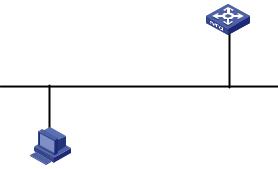
1)Connect the serial port of your PC/terminal to the console port of the switch, as shown in Figure 2-1.
Figure 2-1 Diagram for connecting to the console port of a switch
2-1

2)If you use a PC to connect to the console port, launch a terminal emulation utility (such as Terminal in Windows 3.X or HyperTerminal in Windows 9X/Windows 2000/Windows XP. The following assumes that you are running Windows XP) and perform the configuration shown in Figure 2-2 through Figure 2-4 for the connection to be created. Normally, both sides (that is, the serial port of the PC and the console port of the switch) are configured as those listed in Table 2-1.
Figure 2-2 Create a connection
Figure 2-3 Specify the port used to establish the connection
2-2
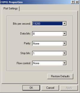
Figure 2-4 Set port parameters
3)Turn on the switch. You will be prompted to press the Enter key if the switch successfully completes POST (power-on self test). The prompt appears after you press the Enter key.
4)You can then configure the switch or check the information about the switch by executing the corresponding commands. You can also acquire help by typing the ? character. Refer to related parts in this manual for information about the commands used for configuring the switch.
Console Port Login Configuration
Common Configuration
Table 2-2 Common configuration of console port login
|
|
Configuration |
|
Remarks |
|
|
|
|
Baud rate |
|
Optional |
|
|
|
|
The default baud rate is 19,200 bps. |
|
|
|
|
|
|
|
|
|
|
|
|
|
|
|
|
|
|
Optional |
|
|
Console port |
Check mode |
|
By default, the check mode of the console port is set to |
|
|
|
|
“none”, which means no check bit. |
|
|
|
configuration |
|
|
|
|
|
Stop bits |
|
Optional |
|
|
|
|
|
||
|
|
|
|
The default stop bits of a console port is 1. |
|
|
|
|
|
|
|
|
|
|
|
|
|
|
|
|
Data bits |
|
Optional |
|
|
|
|
The default data bits of a console port is 8. |
|
|
|
|
|
|
|
|
|
|
|
|
|
|
|
|
Configure the |
|
|
|
|
AUX user interface |
command level |
|
Optional |
|
|
available to the |
|
||
|
|
|
By default, commands of level 3 are available to the |
||
|
|
configuration |
users logging in to |
|
|
|
|
|
users logging in to the AUX user interface. |
||
|
|
|
the AUX user |
|
|
|
|
|
interface |
|
|
|
|
|
|
|
|
|
|
Terminal |
Make terminal |
|
Optional |
|
|
|
By default, terminal services are available in all user |
||
|
|
configuration |
services available |
|
|
|
|
|
interfaces |
||
|
|
|
|
|
|
|
|
|
|
|
|
|
|
|
|
2-3 |
|

|
Configuration |
|
Remarks |
|
|
|
|
Set the maximum |
|
Optional |
|
|
|
number of lines the |
|
|
|
|
|
|
By default, the screen can contain up to 24 lines. |
|
|
|
|
screen can contain |
|
|
|
|
|
|
|
|
|
|
|
|
|
|
|
|
|
Set history |
Optional |
|
|
|
|
command buffer |
By default, the history command buffer can contain up |
|
|
|
|
size |
to 10 commands. |
|
|
|
|
|
|
|
|
|
|
Set the timeout time |
|
Optional |
|
|
|
of a user interface |
|
The default timeout time is 10 minutes. |
|
|
|
|
|
|
|
|
|
|
|
|
|
The change to console port configuration takes effect immediately, so the connection may be disconnected when you log in through a console port and then configure this console port. To configure a console port, you are recommended to log in to the switch in other ways. To log in to a switch through its console port after you modify the console port settings, you need to modify the corresponding settings of the terminal emulation utility running on your PC accordingly in the dialog box shown in Figure 2-4.
Follow these steps to set common configuration of console port login:
|
To do… |
Use the command… |
Remarks |
||
Enter system view |
system-view |
— |
|||
|
|
|
|
||
Enter AUX user interface view |
user-interface aux 0 |
— |
|||
|
|
|
|
|
|
|
|
Set the baud |
|
Optional |
|
|
|
speed speed-value |
The default baud rate of a console |
||
|
|
rate |
|||
|
|
|
port is 19,200 bps. |
||
|
|
|
|
||
|
|
|
|
|
|
|
|
|
|
Optional |
|
|
|
Set the check |
parity { even | none | |
By default, the check mode of a |
|
Configure |
|
mode |
odd } |
console port is none, that is, no |
|
the console |
|
|
check is performed. |
||
port |
|
|
|
|
|
|
Set the stop bits |
stopbits { 1 | 1.5 | 2 } |
Optional |
||
|
|
||||
|
|
The stop bits of a console port is 1. |
|||
|
|
|
|
||
|
|
|
|
|
|
|
|
|
|
Optional |
|
|
|
Set the databits |
databits { 7 | 8 } |
The default databits of a console port |
|
|
|
|
|
is 8. |
|
|
|
|
|
|
|
|
|
|
|
Optional |
|
Configure the command level |
|
By default, commands of level 3 are |
|||
|
available to users logging in to the |
||||
available to users logging in to |
user privilege level level |
||||
AUX user interface, and commands |
|||||
the user interface |
|
||||
|
of level 0 are available to users |
||||
|
|
|
|
||
|
|
|
|
logging in to the VTY user interface. |
|
|
|
|
|
|
|
|
|
|
|
Optional |
|
Enable terminal services |
shell |
By default, terminal services are |
|||
|
|
|
|
available in all user interfaces. |
|
|
|
|
2-4 |
|
|
|
To do… |
|
Use the command… |
|
Remarks |
|
|
|
|
|
Optional |
|
|
|
|
|
By default, the screen can contain up |
|
Set the maximum number of |
|
screen-length |
|
to 24 lines. |
|
lines the screen can contain |
|
screen-length |
|
You can use the screen-length 0 |
|
|
|
|
|
|
|
|
|
|
|
command to disable the function to |
|
|
|
|
|
display information in pages. |
|
|
|
|
|
|
|
|
|
|
|
Optional |
|
Set the history command |
|
history-command |
|
The default history command buffer |
|
|
|
size is 10, that is, a history command |
||
|
buffer size |
|
max-size value |
|
|
|
|
|
buffer of a user can store up to 10 |
||
|
|
|
|
|
|
|
|
|
|
|
commands by default. |
|
|
|
|
|
|
|
|
|
|
|
Optional |
|
|
|
|
|
The default timeout time of a user |
|
|
|
|
|
interface is 10 minutes. |
|
|
|
|
|
With the timeout time being 10 |
|
Set the timeout time for the |
|
idle-timeout minutes |
|
minutes, the connection to a user |
|
|
|
interface is terminated if no operation |
||
|
user interface |
|
[ seconds ] |
|
|
|
|
|
is performed in the user interface |
||
|
|
|
|
|
|
|
|
|
|
|
within 10 minutes. |
|
|
|
|
|
You can use the idle-timeout 0 |
|
|
|
|
|
command to disable the timeout |
|
|
|
|
|
function. |
|
|
|
|
|
|
Console Port Login Configurations for Different Authentication Modes
Table 2-3 Console port login configurations for different authentication modes
|
|
Authentication |
|
|
Authentication related configuration |
|
|
Remarks |
|
|
|
mode |
|
|
|
|
|
||
|
|
|
|
|
|
|
|
|
|
|
|
|
|
|
|
|
|
|
|
|
|
|
|
|
|
|
|
Optional |
|
|
|
None |
Set the authentication mode to none |
|
Refer to Console Port |
||||
|
|
|
Login Configuration with |
||||||
|
|
|
|
|
|
|
|
Authentication Mode |
|
|
|
|
|
|
|
|
|
Being None |
|
|
|
|
|
|
|
|
|||
|
|
|
|
|
Set the authentication mode to local password |
Refer to Console Port |
|||
|
|
Password |
|
authentication |
|
Login Configuration with |
|||
|
|
|
|
|
|
||||
|
|
|
Set the password for local authentication |
|
Authentication Mode |
||||
|
|
|
|
|
|
||||
|
|
|
|
|
|
Being Password. |
|||
|
|
|
|
|
|
|
|
|
|
|
|
|
|
|
Set the authentication mode to scheme |
|
|
|
|
|
|
|
|
|
|
|
|||
|
|
|
|
|
Specify to perform local authentication or |
Refer to Console Port |
|||
|
|
Scheme |
|
remote authentication |
|
Login Configuration with |
|||
|
|
|
|
|
|
Authentication Mode |
|||
|
|
|
|
|
|
|
|
||
|
|
|
|
|
Set user names and passwords locally or on |
|
Being Scheme. |
||
|
|
|
|
|
AAA Server |
|
|
|
|
|
|
|
|
|
|
|
|
|
|
2-5

Changes made to the authentication mode for console port login takes effect after you quit the command-line interface and then log in again.
Console Port Login Configuration with Authentication Mode Being None
Configuration Procedure
Follow these steps to configure console port login with the authentication mode being none:
To do… |
Use the command… |
Remarks |
Enter system view |
system-view |
— |
|
|
|
Enter AUX user interface view |
user-interface aux 0 |
— |
|
|
|
|
|
Required |
Configure not to authenticate |
authentication-mode |
By default, users logging in through |
users |
none |
the console port (AUX user interface) |
|
|
are not authenticated. |
|
|
|
Configuration Example
Network requirements
Assume that the switch is configured to allow users to log in through Telnet, and the current user level is set to the administrator level (level 3). Perform the following configurations for users logging in through the console port (AUX user interface).
zDo not authenticate the users.
zCommands of level 2 are available to the users logging in to the AUX user interface.
zThe baud rate of the console port is 19,200 bps.
zThe screen can contain up to 30 lines.
zThe history command buffer can contain up to 20 commands.
zThe timeout time of the AUX user interface is 6 minutes.
2-6

Network diagram
Figure 2-5 Network diagram for AUX user interface configuration (with the authentication mode being none)
GE1/0/1
Ethernet
Configuration PC
running Telnet
Configuration procedure
# Enter system view.
<Sysname> system-view
# Enter AUX user interface view.
[Sysname] user-interface aux 0
# Specify not to authenticate users logging in through the console port.
[Sysname-ui-aux0] authentication-mode none
# Specify commands of level 2 are available to users logging in to the AUX user interface.
[Sysname-ui-aux0] user privilege level 2
# Set the baud rate of the console port to 19,200 bps.
[Sysname-ui-aux0] speed 19200
# Set the maximum number of lines the screen can contain to 30.
[Sysname-ui-aux0] screen-length 30
# Set the maximum number of commands the history command buffer can store to 20.
[Sysname-ui-aux0] history-command max-size 20
# Set the timeout time of the AUX user interface to 6 minutes.
[Sysname-ui-aux0] idle-timeout 6
After the above configuration, you need to modify the configuration of the terminal emulation utility running on the PC accordingly in the dialog box shown in Figure 2-4 to log in to the switch successfully.
Console Port Login Configuration with Authentication Mode Being Password
Configuration Procedure
Follow these steps to configure console port login with the authentication mode being password:
2-7
|
To do… |
|
Use the command… |
|
Remarks |
|
Enter system view |
|
system-view |
|
— |
|
|
|
|
|
|
|
Enter AUX user interface |
|
user-interface aux 0 |
— |
|
|
view |
|
|||
|
|
|
|
|
|
|
|
|
|
|
|
|
|
|
|
|
Required |
|
Configure to authenticate |
|
authentication-mode |
|
By default, users logging in to a switch |
|
|
|
through the console port are not |
||
|
users using the local |
|
|
||
|
|
password |
|
authenticated; while those logging in |
|
|
password |
|
|
||
|
|
|
|
through Modems or Telnet are |
|
|
|
|
|
|
|
|
|
|
|
|
authenticated. |
|
|
|
|
|
|
|
|
|
set authentication |
|
|
|
Set the local password |
|
password { cipher | |
Required |
|
|
|
|
simple } password |
|
|
|
|
|
|
|
|
Configuration Example
Network requirements
Assume the switch is configured to allow users to log in through Telnet, and the user level is set to the administrator level (level 3). Perform the following configurations for users logging in through the console port (AUX user interface).
z
z
z
z
z
z
z
Authenticate the users using passwords.
Set the local password to 123456 (in plain text). The commands of level 2 are available to the users. The baud rate of the console port is 19,200 bps. The screen can contain up to 30 lines.
The history command buffer can store up to 20 commands. The timeout time of the AUX user interface is 6 minutes.
Network diagram
Figure 2-6 Network diagram for AUX user interface configuration (with the authentication mode being password)
GE1/0/1
Ethernet
Configuration PC
running Telnet
Configuration procedure
# Enter system view.
2-8
<Sysname> system-view
# Enter AUX user interface view.
[Sysname] user-interface aux 0
# Specify to authenticate users logging in through the console port using the local password.
[Sysname-ui-aux0] authentication-mode password
# Set the local password to 123456 (in plain text).
[Sysname-ui-aux0] set authentication password simple 123456
# Specify commands of level 2 are available to users logging in to the AUX user interface.
[Sysname-ui-aux0] user privilege level 2
# Set the baud rate of the console port to 19,200 bps.
[Sysname-ui-aux0] speed 19200
# Set the maximum number of lines the screen can contain to 30.
[Sysname-ui-aux0] screen-length 30
# Set the maximum number of commands the history command buffer can store to 20.
[Sysname-ui-aux0] history-command max-size 20
# Set the timeout time of the AUX user interface to 6 minutes.
[Sysname-ui-aux0] idle-timeout 6
After the above configuration, you need to modify the configuration of the terminal emulation utility running on the PC accordingly in the dialog box shown in Figure 2-4 to log in to the switch successfully.
Console Port Login Configuration with Authentication Mode Being Scheme
Configuration Procedure
Follow these steps to configure console port login with the authentication mode being scheme:
To do… |
Use the command… |
Remarks |
|
Enter system view |
system-view |
— |
|
|
|
|
|
Enter AUX user interface view |
user-interface aux 0 |
— |
|
|
|
|
|
|
|
Required |
|
|
|
The specified AAA scheme |
|
|
|
determines what authentication |
|
Configure to authenticate |
authentication-mode |
mode is adopted, local or |
|
scheme [ command- |
RADIUS. |
||
users in the scheme mode |
|||
authorization ] |
By default, users logging in |
||
|
|||
|
|
through the console port (AUX |
|
|
|
user interface) are not |
|
|
|
authenticated. |
|
|
|
|
|
Quit to system view |
quit |
— |
|
|
|
|
2-9

|
To do… |
|
Use the command… |
|
Remarks |
|
||
|
|
Enter the |
|
|
|
Optional |
|
|
|
|
default ISP |
|
domain domain-name |
|
By default, the local AAA scheme |
||
|
|
domain view |
|
|
|
|||
|
|
|
|
|
is applied. |
|
|
|
|
|
|
|
|
|
|
|
|
|
|
Specify the AAA |
|
scheme { local | none | |
|
If you specify to apply the local |
||
|
|
scheme to be |
|
radius-scheme |
|
AAA scheme, you need to |
||
|
|
applied to the |
|
radius-scheme-name |
|
perform the configuration |
|
|
|
Configure |
domain |
|
[ local ] } |
|
concerning local user as well. |
||
|
|
|
|
|
If you specify to apply a RADIUS |
|||
|
|
|
|
|
||||
|
the |
|
|
|
|
|||
|
|
|
|
|
scheme, you need to perform the |
|||
|
authenticati |
|
|
|
|
|||
|
|
|
|
|
following configuration as well: |
|||
|
on mode |
|
|
|
|
|||
|
|
|
|
|
z Perform |
|
RADIUS |
|
|
|
|
|
|
|
|
||
|
|
Quit to system |
|
|
|
configuration |
on the |
switch. |
|
|
|
quit |
|
(Refer to the |
AAA |
part for |
|
|
|
view |
|
|
||||
|
|
|
|
|
more.) |
|
|
|
|
|
|
|
|
|
|
|
|
|
|
|
|
|
|
z Configure the user name and |
||
|
|
|
|
|
|
password accordingly on the |
||
|
|
|
|
|
|
AAA server. (Refer to the user |
||
|
|
|
|
|
|
manual of AAA server.) |
||
|
Create a local user (Enter local |
|
local-user user-name |
|
Required |
|
|
|
|
|
|
No local user exists by default. |
|||||
|
user view.) |
|
|
|
||||
|
Set the authentication |
|
password { simple | cipher } |
|
Required |
|
|
|
|
password for the local user |
|
password |
|
|
|
||
|
|
|
|
|
|
|||
|
|
|
|
|
|
|
|
|
|
Specify the service type for |
|
service-type terminal [ level |
|
Required |
|
|
|
|
AUX users |
|
level ] |
|
|
|
||
|
|
|
|
|
|
|||
|
|
|
|
|
|
|
|
|
Note that:
If you configure to authenticate the users in the scheme mode, the command level available to users logging in to a switch depends on the command level specified in the AAA scheme:
zWhen the AAA scheme is local authentication, the command level available to users depends on the service-type terminal [ level level ] command.
zWhen the AAA scheme is RADIUS authentication, you need to set the corresponding user level on the RADIUS server.
For the introduction to AAA, RADIUS, refer to the AAA part of this manual.
Configuration Example
Network requirements
Assume the switch is configured to allow users to log in through Telnet, and the user level is set to the administrator level (level 3). Perform the following configurations for users logging in through the console port (AUX user interface).
zConfigure the local user name as guest.
zSet the authentication password of the local user to 123456 (in plain text).
2-10
z
z
z
z
z
z
Set the service type of the local user to Terminal and the command level to 2. Configure to authenticate the users in the scheme mode.
The baud rate of the console port is 19,200 bps. The screen can contain up to 30 lines.
The history command buffer can store up to 20 commands. The timeout time of the AUX user interface is 6 minutes.
Network diagram
Figure 2-7 Network diagram for AUX user interface configuration (with the authentication mode being scheme)
GE1/0/1
Ethernet
Configuration PC
running Telnet
Configuration procedure
# Enter system view.
<Sysname> system-view
# Create a local user named guest and enter local user view.
[Sysname] local-user guest
# Set the authentication password to 123456 (in plain text).
[Sysname-luser-guest] password simple 123456
# Set the service type to Terminal, Specify commands of level 2 are available to users logging in to the AUX user interface.
[Sysname-luser-guest] service-type terminal level 2
[Sysname-luser-guest] quit
# Enter AUX user interface view.
[Sysname] user-interface aux 0
# Configure to authenticate users logging in through the console port in the scheme mode.
[Sysname-ui-aux0] authentication-mode scheme
# Set the baud rate of the console port to 19,200 bps.
[Sysname-ui-aux0] speed 19200
# Set the maximum number of lines the screen can contain to 30.
[Sysname-ui-aux0] screen-length 30
# Set the maximum number of commands the history command buffer can store to 20.
2-11
[Sysname-ui-aux0] history-command max-size 20
# Set the timeout time of the AUX user interface to 6 minutes.
[Sysname-ui-aux0] idle-timeout 6
After the above configuration, you need to modify the configuration of the terminal emulation utility running on the PC accordingly in the dialog box shown in Figure 2-4 to log in to the switch successfully.
2-12

3 Logging In Through Telnet
Go to these sections for information you are interested in:
z
z
z
Introduction
Telnet Configuration with Authentication Mode Being None Telnet Configuration with Authentication Mode Being Password
Introduction
Switch 4500 supports Telnet. You can manage and maintain a switch remotely by Telnetting to the switch.
To log in to a switch through Telnet, the corresponding configuration is required on both the switch and the Telnet terminal.
You can also log in to a switch through SSH. SSH is a secure shell added to Telnet. Refer to the SSH Operation for related information.
Table 3-1 Requirements for Telnetting to a switch
|
Item |
Requirement |
|
|
|
The IP address is configured for the VLAN of the switch, and the route between |
|
|
|
the switch and the Telnet terminal is reachable. (Refer to the IP Address |
|
|
Switch |
Configuration – IP Performance Configuration and Routing Protocol parts for |
|
|
more.) |
|
|
|
|
|
|
|
|
The authentication mode and other settings are configured. Refer to Table 3-2 |
|
|
|
and Table 3-3. |
|
|
|
|
|
|
Telnet terminal |
Telnet is running. |
|
|
|
|
|
|
The IP address of the VLAN interface of the switch is available. |
|
|
|
|
|
|
|
|
|
|
|
|
|
|
Telnetting to a switch using IPv6 protocols is similar to Telnetting to a switch using IPv4 protocols. Refer to the IPv6 Management part for related information.
Common Configuration to Control Telnet Access
Table 3-2 Common Telnet configuration
|
|
|
Configuration |
Description |
|
|
|
VTY user |
|
Configure the command |
Optional |
|
|
|
level available to users |
||
|
|
interface |
|
By default, commands of level 0 are available to |
|
|
|
|
logging in to the VTY user |
||
|
|
configuration |
|
users logging in to a VTY user interface. |
|
|
|
|
interface |
||
|
|
|
|
|
|
|
|
|
|
|
|
|
|
|
3-1 |
|
|
|
|
|
Configuration |
|
Description |
|
|
|
|
|
Configure the protocols the |
|
Optional |
|
|
|
|
|
By default, Telnet and SSH protocol are |
|
|
|
|
|
user interface supports |
|
|
|
|
|
|
|
supported. |
|
|
|
|
|
|
|
|
|
|
|
|
|
|
|
|
|
|
|
Set the commands to be |
|
Optional |
|
|
|
|
executed automatically after |
|
By default, no command is executed |
|
|
|
|
a user log in to the user |
|
automatically after a user logs into the VTY user |
|
|
|
|
interface successfully |
|
interface. |
|
|
|
|
|
|
|
|
|
|
|
Make terminal services |
|
Optional |
|
|
|
|
|
By default, terminal services are available in all |
|
|
|
|
|
available |
|
|
|
|
|
|
|
user interfaces |
|
|
|
|
|
|
|
|
|
|
|
|
|
|
|
|
|
|
|
Set the maximum number of |
|
Optional |
|
|
VTY terminal |
|
lines the screen can contain |
|
By default, the screen can contain up to 24 lines. |
|
|
|
|
|
|
|
|
|
configuration |
|
Set history command buffer |
|
Optional |
|
|
|
|
|
||
|
|
|
|
|
By default, the history command buffer can |
|
|
|
|
|
size |
|
|
|
|
|
|
|
contain up to 10 commands. |
|
|
|
|
|
|
|
|
|
|
|
|
|
|
|
|
|
|
|
Set the timeout time of a user |
Optional |
|
|
|
|
|
interface |
The default timeout time is 10 minutes. |
|
|
|
|
|
|
|
|
Follow these steps to set common telnet configuration:
To do… |
Use the command… |
Remarks |
|
Enter system view |
system-view |
— |
|
|
|
|
|
Enter one or more VTY user |
user-interface vty |
— |
|
interface views |
first-number [ last-number ] |
||
|
|||
|
|
|
|
Configure the command level |
|
Optional |
|
|
By default, commands of level 0 |
||
available to users logging in to |
user privilege level level |
||
are available to users logging in to |
|||
VTY user interface |
|
||
|
VTY user interfaces. |
||
|
|
||
|
|
|
|
Configure the protocols to be |
protocol inbound { all | |
Optional |
|
supported by the VTY user |
By default, both Telnet protocol |
||
ssh | telnet } |
|||
interface |
and SSH protocol are supported. |
||
|
|||
|
|
|
|
Set the commands to be |
|
Optional |
|
|
By default, no command is |
||
executed automatically after a |
auto-execute command |
||
executed automatically after a |
|||
user logs in to the user |
text |
||
user logs into the VTY user |
|||
interface successfully |
|
||
|
interface. |
||
|
|
||
|
|
|
|
|
|
Optional |
|
Enable terminal services |
shell |
By default, terminal services are |
|
|
|
available in all user interfaces. |
|
|
|
|
|
|
|
Optional |
|
Set the maximum number of |
|
By default, the screen can contain |
|
screen-length |
up to 24 lines. |
||
lines the screen can contain |
screen-length |
You can use the screen-length 0 |
|
|
|
||
|
|
command to disable the function to |
|
|
|
display information in pages. |
|
|
|
|
3-2
|
To do… |
|
Use the command… |
|
Remarks |
|
|
|
|
|
Optional |
|
Set the history command buffer |
|
history-command |
|
The default history command |
|
|
|
buffer size is 10, that is, the history |
||
|
size |
|
max-size value |
|
command buffer of a user can |
|
|
|
|
|
store up to 10 commands by |
|
|
|
|
|
default. |
|
|
|
|
|
|
|
|
|
|
|
Optional |
|
|
|
|
|
The default timeout time of a user |
|
|
|
|
|
interface is 10 minutes. |
|
|
|
|
|
With the timeout time being 10 |
|
Set the timeout time of the VTY |
|
idle-timeout minutes |
|
minutes, the connection to a user |
|
|
|
interface is terminated if no |
||
|
user interface |
|
[ seconds ] |
|
|
|
|
|
operation is performed in the user |
||
|
|
|
|
|
|
|
|
|
|
|
interface within 10 minutes. |
|
|
|
|
|
You can use the idle-timeout 0 |
|
|
|
|
|
command to disable the timeout |
|
|
|
|
|
function. |
|
|
|
|
|
|
Telnet Configurations for Different Authentication Modes
Table 3-3 Telnet configurations for different authentication modes
|
|
Authentication |
|
|
Authentication related configuration |
|
|
Description |
|
|
|
mode |
|
|
|
|
|
||
|
|
|
|
|
|
|
|
|
|
|
|
|
|
|
|
|
|
|
|
|
|
|
|
|
|
|
|
Refer to Console Port Login |
|
|
|
None |
Set the authentication mode to none |
|
Configuration with |
||||
|
|
|
Authentication Mode Being |
||||||
|
|
|
|
|
|
|
|
||
|
|
|
|
|
|
|
|
None. |
|
|
|
|
|
|
|
|
|
||
|
|
|
|
|
Set the authentication mode to local |
|
Refer to Console Port Login |
||
|
|
Password |
|
password authentication |
|
Configuration with |
|||
|
|
|
|
|
|
Authentication Mode Being |
|||
|
|
|
|
|
Set the password for local authentication |
|
|||
|
|
|
|
|
|
Password. |
|||
|
|
|
|
|
|
|
|
|
|
|
|
|
|
|
Set the authentication mode to scheme |
|
|
|
|
|
|
|
|
|
|
|
|
Refer to Console Port Login |
|
|
|
|
|
|
Specify to perform local authentication or |
|
|||
|
|
Scheme |
|
|
Configuration with |
||||
|
|
|
remote authentication |
|
|||||
|
|
|
|
Authentication Mode Being |
|||||
|
|
|
|
|
|
|
|
||
|
|
|
|
|
Set user names and passwords locally or |
|
Scheme. |
||
|
|
|
|
|
on AAA Server |
|
|
|
|
|
|
|
|
|
|
|
|
|
|
3-3

To improve security and prevent attacks to the unused Sockets, TCP 23 and TCP 22, ports for Telnet and SSH services respectively, will be enabled or disabled after corresponding configurations.
zIf the authentication mode is none, TCP 23 will be enabled, and TCP 22 will be disabled.
zIf the authentication mode is password, and the corresponding password has been set, TCP 23 will be enabled, and TCP 22 will be disabled.
zIf the authentication mode is scheme, there are three scenarios: when the supported protocol is specified as telnet, TCP 23 will be enabled; when the supported protocol is specified as ssh, TCP 22 will be enabled; when the supported protocol is specified as all, both the TCP 23 and TCP 22 port will be enabled.
Telnet Configuration with Authentication Mode Being None
Configuration Procedure
Follow these steps to configure Telnet with the authentication mode being none:
To do… |
Use the command… |
Remarks |
|
Enter system view |
system-view |
— |
|
|
|
|
|
Enter one or more VTY user |
user-interface vty |
— |
|
interface views |
first-number [ last-number ] |
||
|
|||
|
|
|
|
Configure not to authenticate |
|
Required |
|
users logging in to VTY user |
authentication-mode none |
By default, VTY users are |
|
interfaces |
|
authenticated after logging in. |
|
|
|
|
Note that if you configure not to authenticate the users, the command level available to users logging in to a switch depends on the user privilege level level command
Configuration Example
Network requirements
Assume current user logins through the console port, and the current user level is set to the administrator level (level 3). Perform the following configurations for users logging in through VTY 0 using Telnet.
z
z
z
z
z
z
Do not authenticate the users.
Commands of level 2 are available to the users. Telnet protocol is supported.
The screen can contain up to 30 lines.
The history command buffer can contain up to 20 commands. The timeout time of VTY 0 is 6 minutes.
3-4
Network diagram
Figure 3-1 Network diagram for Telnet configuration (with the authentication mode being none)
Configuration procedure
# Enter system view.
<Sysname> system-view
# Enter VTY 0 user interface view.
[Sysname] user-interface vty 0
# Configure not to authenticate Telnet users logging in to VTY 0.
[Sysname-ui-vty0] authentication-mode none
# Specify commands of level 2 are available to users logging in to VTY 0.
[Sysname-ui-vty0] user privilege level 2
# Configure Telnet protocol is supported.
[Sysname-ui-vty0] protocol inbound telnet
# Set the maximum number of lines the screen can contain to 30.
[Sysname-ui-vty0] screen-length 30
# Set the maximum number of commands the history command buffer can store to 20.
[Sysname-ui-vty0] history-command max-size 20
# Set the timeout time to 6 minutes.
[Sysname-ui-vty0] idle-timeout 6
Telnet Configuration with Authentication Mode Being Password
Configuration Procedure
Follow these steps to configure Telnet with the authentication mode being password:
To do… |
Use the command… |
Remarks |
|
Enter system view |
system-view |
— |
|
|
|
|
|
Enter one or more VTY |
user-interface vty |
— |
|
user interface views |
first-number [ last-number ] |
||
|
|||
|
|
|
|
Configure to authenticate |
|
|
|
users logging in to VTY |
authentication-mode |
Required |
|
user interfaces using the |
password |
||
|
|||
local password |
|
|
|
|
|
|
|
|
set authentication |
|
|
Set the local password |
password { cipher | simple } |
Required |
|
|
password |
|
|
|
|
|
3-5

When the authentication mode is password, the command level available to users logging in to the user interface is determined by the user privilege level command.
Configuration Example
Network requirements
Assume current user logins through the console port and the current user level is set to the administrator level (level 3). Perform the following configurations for users logging in to VTY 0 using Telnet.
zAuthenticate users using the local password.
zSet the local password to 123456 (in plain text).
zCommands of level 2 are available to the users.
zTelnet protocol is supported.
zThe screen can contain up to 30 lines.
zThe history command buffer can contain up to 20 commands.
zThe timeout time of VTY 0 is 6 minutes.
Network diagram
Figure 3-2 Network diagram for Telnet configuration (with the authentication mode being password)
Configuration procedure
# Enter system view.
<Sysname> system-view
# Enter VTY 0 user interface view.
[Sysname] user-interface vty 0
# Configure to authenticate users logging in to VTY 0 using the password.
[Sysname-ui-vty0] authentication-mode password
# Set the local password to 123456 (in plain text).
[Sysname-ui-vty0] set authentication password simple 123456
# Specify commands of level 2 are available to users logging in to VTY 0.
[Sysname-ui-vty0] user privilege level 2
# Configure Telnet protocol is supported.
[Sysname-ui-vty0] protocol inbound telnet
# Set the maximum number of lines the screen can contain to 30.
[Sysname-ui-vty0] screen-length 30
# Set the maximum number of commands the history command buffer can store to 20.
[Sysname-ui-vty0] history-command max-size 20
# Set the timeout time to 6 minutes.
[Sysname-ui-vty0] idle-timeout 6
3-6
Telnet Configuration with Authentication Mode Being Scheme
Configuration Procedure
Follow these steps to configure Telnet with the authentication mode being scheme:
|
To do… |
|
Use the command… |
|
|
|
Remarks |
|
|
|||
|
Enter system view |
|
system-view |
|
— |
|
|
|
|
|
||
|
|
|
|
|
|
|
|
|
|
|
|
|
|
Enter one or more VTY user |
|
user-interface vty |
— |
|
|
|
|
|
|||
|
interface views |
|
|
first-number [ last-number ] |
|
|
|
|
|
|||
|
|
|
|
|
|
|
|
|
|
|||
|
|
|
|
|
|
|
|
|
|
|
|
|
|
|
|
|
|
|
|
Required |
|
|
|
|
|
|
Configure to authenticate |
|
authentication-mode |
|
The specified AAA scheme |
|
|
|||||
|
|
|
determines what authentication |
|
||||||||
|
|
scheme [ command- |
|
|
||||||||
|
users in the scheme mode |
|
|
mode is adopted, local or RADIUS. |
||||||||
|
|
authorization ] |
|
|||||||||
|
|
|
|
|
|
Users are authenticated locally by |
||||||
|
|
|
|
|
|
|
||||||
|
|
|
|
|
|
|
default. |
|
|
|
|
|
|
|
|
|
|
|
|
|
|
|
|
|
|
|
Quit to system view |
|
quit |
|
— |
|
|
|
|
|
||
|
|
|
|
|
|
|
|
|
|
|
|
|
|
|
|
Enter the |
|
|
|
Optional |
|
|
|
|
|
|
|
|
default ISP |
|
domain domain-name |
|
By default, the local AAA scheme is |
|||||
|
|
|
domain view |
|
|
|
||||||
|
|
|
|
|
|
applied. If you specify to apply the |
||||||
|
|
|
|
|
|
|
||||||
|
|
|
Configure the |
|
scheme { local | none | |
|
local AAA scheme, you need to |
|
||||
|
|
|
|
|
perform the configuration |
|
|
|||||
|
|
|
AAA scheme |
|
radius-scheme |
|
|
|
||||
|
|
|
|
|
concerning local user as well. |
|
||||||
|
Configure |
|
to be applied |
|
radius-scheme-name |
|
|
|||||
|
|
|
|
If you specify to apply RADIUS |
|
|||||||
|
|
to the domain |
|
[ local ] } |
|
|
||||||
|
the |
|
|
|
|
|
scheme, you need to perform the |
|||||
|
|
|
|
|
|
|||||||
|
authenticati |
|
|
|
|
|
following configuration as well: |
|
||||
|
on scheme |
|
|
|
|
|
z |
Perform |
|
AAA&RADIUS |
||
|
|
|
|
|
|
|
|
|||||
|
|
|
Quit to |
|
|
|
|
configuration |
on the |
switch. |
||
|
|
|
|
quit |
|
|
(Refer to the AAA part for more.) |
|||||
|
|
|
system view |
|
|
|
Configure |
the |
user name |
and |
||
|
|
|
|
|
|
z |
||||||
|
|
|
|
|
|
|
||||||
|
|
|
|
|
|
|
|
password |
accordingly |
on |
the |
|
|
|
|
|
|
|
|
|
AAA server. (Refer to the user |
||||
|
|
|
|
|
|
|
|
manual of AAA server.) |
|
|
||
|
Create a local user and enter |
|
local-user user-name |
|
No local user exists by default. |
|
||||||
|
local user view |
|
|
|
|
|
|
|
|
|
|
|
|
Set the authentication |
|
password { simple | cipher } |
|
Required |
|
|
|
|
|||
|
password for the local user |
|
password |
|
|
|
|
|
|
|
||
|
Specify the service type for |
|
service-type telnet [ level |
|
Required |
|
|
|
|
|||
|
VTY users |
|
|
level ] |
|
|
|
|
|
|||
|
|
|
|
|
|
|
|
|
|
|||
|
|
|
|
|
|
|
|
|
|
|
|
|
Note that:
If you configure to authenticate the users in the scheme mode, the command level available to the users logging in to the switch depends on the user level defined in the AAA scheme.
zWhen the AAA scheme is local, the user level depends on the service-type { ftp | lan-access | { ssh | telnet | terminal }* [ level level ] } command.
zWhen the AAA scheme is RADIUS, you need to specify the user level of a user on the corresponding RADIUS server.
3-7
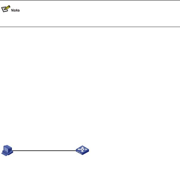
Refer to the AAA part of this manual for information about AAA, RADIUS.
Configuration Example
Network requirements
Assume current user logins through the console port and the user level is set to the administrator level (level 3). Perform the following configurations for users logging in to VTY 0 using Telnet.
z
z
z
z
z
z
z
z
Configure the local user name as guest.
Set the authentication password of the local user to 123456 (in plain text). Set the service type of VTY users to Telnet and the command level to 2. Configure to authenticate users logging in to VTY 0 in scheme mode. Only Telnet protocol is supported in VTY 0.
The screen can contain up to 30 lines.
The history command buffer can store up to 20 commands. The timeout time of VTY 0 is 6 minutes.
Network diagram
Figure 3-3 Network diagram for Telnet configuration (with the authentication mode being scheme)
Configuration procedure
# Enter system view.
<Sysname> system-view
# Create a local user named guest and enter local user view.
[Sysname] local-user guest
# Set the authentication password of the local user to 123456 (in plain text).
[Sysname-luser-guest] password simple 123456
# Set the service type to Telnet, Specify commands of level 2 are available to users logging in to VTY 0..
[Sysname-luser-guest] service-type telnet level 2
[Sysname-luser-guest] quit
# Enter VTY 0 user interface view.
[Sysname] user-interface vty 0
# Configure to authenticate users logging in to VTY 0 in the scheme mode.
[Sysname-ui-vty0] authentication-mode scheme
# Configure Telnet protocol is supported.
[Sysname-ui-vty0] protocol inbound telnet
3-8
Loading...