


OfficeConnect®
ADSL Wireless 108 Mbps
11g Firewall Router
3CRWDR200A-75 3CRWDR200B-75
Installation Guide
Guía de instalación
Guide d’installation
Manuale di installazione
Installationsanleitung
Installations Guide
Guia de Instalação
www.3com.com
Part No. 10015037
Model Number: WL-553
Published April 2006

Introducing the Router |
1 |
INTRODUCING THE ROUTER
This Guide takes you through the basic steps necessary to install and configure your OfficeConnect ADSL Wireless 108 Mbps 11g Firewall Router, and establish a connection from your computers to the Internet. Throughout this Guide, the OfficeConnect ADSL Wireless 108 Mbps 11g Firewall Router is simply referred to as the Router.
Note: 3Com recommends that you use wired (Ethernet) connection to perform the initial setup.
GB
Your Package Contains: • One OfficeConnect ADSL Wireless 108 Mbps 11g Firewall Router
•One power adapter for use with the Router
•Four rubber feet
•One RJ45 cable
•One RJ11 cable
•One CD-ROM containing the User Guide
•This Installation Guide
•One Support and Safety Information Sheet
•One Warranty Flyer
System Requirements Before starting, ensure that:
•You already have an ADSL broadband account.
•You have a computer that has an Ethernet connection available and is already correctly configured for communication with the Internet. Your computer must be able to connect to the Internet via the modem, and must have a Web browser installed.
•There are no other DHCP server devices on your local network that are responsible for allocating IP addresses to your computers and other network connected devices. Your Router will perform this function by default.
•If you require wireless access, you have a computer that has a wireless 802.11b or 802.11g adapter card installed.
If one or more of these conditions are not met, refer to the OfficeConnect ADSL Wireless 108 Mbps 11g Firewall Router User Guide provided on the accompanying CD-ROM for further guidance.

2 Front Panel
FRONT PANEL
2 |
|
4 |
|
1 |
3 |
5 |
6 |
|
|
||
3CRWDR200A/B-75 |
|
|
LAN Status |
Alert Power WLAN |
SYNC |
Data |
1 2 3 4 |
OfficeConnect ADSL Wireless 108 Mbps 11g Firewall Router |
DSL |
DSL |
Green = Link, Flash = Activity |
|
|
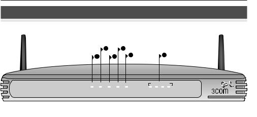
1. Alert LED amber
This LED has a number of functions:
•It will flash rapidly during the power up self test. If it then remains on the unit self test has failed (refer to the User Guide).
•It will flash rapidly during software upgrade.
•It will flash rapidly during the reset to Factory defaults. If the reset button on the rear panel has been used to reset the unit to Factory defaults the Alert LED will then slow flash until power is removed.
•It will flash on for 2 seconds when the firewall detects a hacker attack.
2.Power LED green
If the LED is on, it indicates that the Router is powered on.
3. Wireless LAN (WLAN) Status LED green
If the LED is on, it indicates that wireless networking is enabled. If the LED is flashing, the link is OK and data is being transmitted or received. If the LED is off, the wireless LAN has been disabled on the Router, or there is a problem (refer to the User Guide).
4. SYNC DSL LED green
If the LED is on, it indicates that the DSL connection is present. This LED flashes during configuration at power up.
5. Data DSL LED green
If the LED is on, it indicates that your Username/Password has been authenticated successfully with your ISP. It flashes to indicate activity on your DSL connection.
6. LAN Status LED green
If the LED is on, the link between the port and the next piece of network equipment is OK. If the LED is flashing, the link is OK and data is being transmitted or received. If the LED is off, nothing is connected, or the connected device is switched off, or there is a problem with the connection (refer to the User Guide). The port will automatically adjust to the correct speed and duplex.

Rear Panel |
3 |
REAR PANEL
7 |
8 |
|
|
9 |
|
|
10 |
11 |
12 |
|
|
|
|
|
|
|
|
|
GB |
|
|
|
|
|
|
|
|
|
12 VDC |
|
|
|
|
|
|
|
|
|
1.25A MAX |
|
ADSL |
4 |
3 |
2 |
1 |
LAN |
RESET |
POWER |
OK |
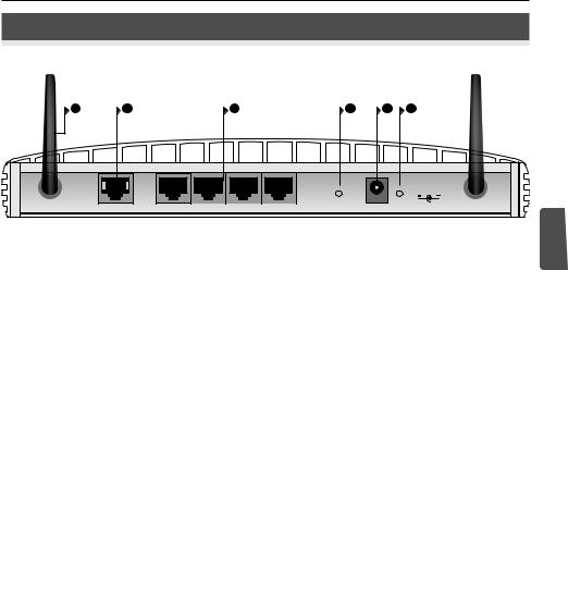
7. Wireless Antennae
For optimum wireless coverage, place the antennae in a ‘V’ position.
8. ADSL
The ADSL port is used to connect the Router to the ADSL wall socket connection. Use an RJ11 cable to connect from the ADSL port to the ADSL wall connection.
9. Ethernet Ports
Using suitable RJ45 cables, you can connect your Router to a computer, or to any other piece of equipment that has an Ethernet connection (for example, a hub or a switch). These ports have an automatic MDI/MDIX feature, which means you can use either a straight-through or a crossover cable.
10. Reset Button
To reboot the Router, press the reset button for 1 second. If you want to reset the Router to factory defaults or if you cannot access the Web management interface (for example, due to a lost password), press the reset button for 5 seconds.
11. Power Adapter Socket
Only use the power adapter that is supplied with the Router. Do not use any other adapter.
12. Power Adapter OK LED
The LED indicates that the power adapter is supplying power to the Router. If the LED is off, there may be a problem with the power adapter or adapter cable.

4Positioning and Installing Your Router
1.POSITIONING AND INSTALLING YOUR ROUTER
Safety Information  WARNING: Please read the ‘Important Safety Information’ section in the Support and Safety Information sheet before you start.
 VORSICHT: Bitte lesen Sie den Abschnitt „Wichtige Sicherheitsinformationen” sorgfältig durch, bevor Sie das Gerät in Betrieb nehmen.
 AVERTISSEMENT: Lisez attentivement le paragraphe “Remarques relatives à la sécurité” avant de mettre votre routeur sous tension.
When positioning your Router, ensure that:
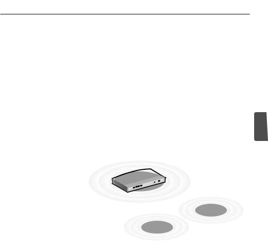
•The Router is centrally located to the wireless computers that will connect to it. A suitable location might be on top of a high shelf or similar furniture to optimize wireless connections to computers in both horizontal and vertical directions, allowing coverage throughout.
•It is out of direct sunlight and away from sources of heat.
•Cabling is away from power lines, fluorescent lighting fixtures, and sources of electrical noise such as radios, transmitters and broadband amplifiers.
•To meet FCC radiation exposure regulations, the Router should be located in a position that maintains a minimum distance of 20 cm (8 inches) from any personnel (refer to the User Guide for details).
•Water or moisture cannot enter the case of the unit.
•Air flow around the unit and through the vents on the side of the case is not restricted. 3Com recommends that you provide a minimum of 25 mm (1 in.) clearance.
Using the Rubber Feet Use the four self-adhesive rubber feet to prevent your Router from moving around on your desk or when stacking with other flat top units. Only stick the feet to the marked areas at each corner of the underside of your Router.
|
Positioning and Installing Your Router |
5 |
|
|
|
Connecting Your Router 1. |
Connect the power adapter to the Router and wait for the Power LED to |
|
|
illuminate. |
|
2. |
Ensure that your computer is switched on. |
|
3. |
Connect your computer to one of the 10/100 LAN ports on the Router. |
|
|
The LAN Port Status LED should turn green. |
|
4. |
Connect the RJ11 cable from the ADSL port on the Router to your ADSL |
|
|
socket on the wall. |
|
Connecting to a Hub or |
To share your Router with more than four users, you will need an additional |
GB |
Switch |
hub or switch. Connect a LAN port on your Router to the hub or switch (for |
|
|
example, OfficeConnect Dual Speed Switch 8). |
|
Power
Supply Unit
Internet
3Com OfficeConnect
ADSL Wireless 108 Mbps 11g Firewall Router
Telephone
Socket
Splitter/
Microfilter Block
Wireless
Users
Your PC
Example Network with OfficeConnect ADSL Wireless 108 Mbps 11g Firewall Router
6Installing a Splitter and Micro-filter
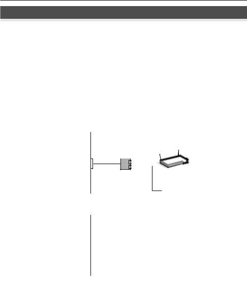
2.INSTALLING A SPLITTER AND MICRO-FILTER
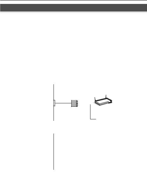
A splitter and micro-filter allow you to use your Router and telephone at the same time. The splitter connects to the ADSL wall connection, and then provides two connectors:
•An RJ11 connector which connects to the Router with the RJ11 cable
•A telephone jack connector which can be connected to your telephone
There must also be a micro-filter between the splitter and the telephone. The micro-filter ensures that DSL data signal does not interfere with the telephone voice signal. A micro-filter must be installed inline with each telephone to prevent signal interference. Splitters are now available with built in microfilters, which simplifies the setup as shown in the diagram below. Splitters and micro-filters can be obtained from your ISP or a computer store.
|
|
Combind Splitter |
||||
|
Wall |
and Micro-filter |
||||
|
|
|
|
|
|
|
|
socket |
|
|
|
|
|
|
|
|
|
|
|
|
|
|
|
|
|
||
|
|
|
|
|
|
|
|
|
|
|
|
|
|
|
|
|
|
|
|
|
OfficeConnect |
® |
ADSL Wireless |
108 Mbps 11g Firewall Router |
||
Phone
|
For Telephone Extensions |
||
|
Wall |
Micro-filter |
|
|
|
|
|
|
socket |
|
|
|
|
|
|
|
|
|
|
|
|
|
|
Phone

Connecting to Your ISP |
7 |
3. CONNECTING TO YOUR ISP
Before you can configure the Router, you need to know the IP allocation method used by your ISP. There are four different methods that the Router can use to connect to the Internet, as described below. For all methods, you need to know the VPI (Virtual Path Identifier), VCI (Virtual Channel Identifier) and the Encapsulation (LLC or VC Mux). The Router defaults for the VPI and VCI should cater for most ISPs. Your ISP can provide you with the required information.
1. PPPoE
GB
To configure the gateway, you will need to know the user name and password to log in to your ISP account. If you have been using a PPPoE client on your computer, you can disable it as it is no longer needed. If your ISP provides you with a static IP address, enter this IP address in the Internet Settings section of the Router Web interface. Otherwise, your ISP will automatically assign your Router an IP address.
2.PPPoA
This is similar to PPPoE but is used mainly in the UK. To configure the gateway, you will need to know the user name and password to log in to your ISP account. If your ISP provides you with a static IP address, enter this IP address in the Internet Settings section of the Router Web interface. Otherwise, your ISP will automatically assign your Router an IP address.
3.Bridge Mode for a Single Computer (RFC 1483 Bridging Mode)
In this mode, the Router is set into a bridging mode to connect the LAN and WAN networks. Traffic is limited between the two networks based on hardware addresses and so limits the LAN side to a single computer.
4.Routing Mode over ATM (RFC 1483 Bridging Mode)
Routing mode over ATM means that the Router has a fixed IP address to connect to the Internet. Your ISP will provide the Router with a fixed IP address, the subnet mask and the ISP’s gateway address. You need to enter this information in the Internet Settings section of the Router Web interface.

8Running the Setup Wizard
4.RUNNING THE SETUP WIZARD
1.If you have not already done so, restart your computer.
2.Launch your Web browser and try to connect to the Router by typing the following URL in the address or location bar: http://192.168.1.1. If you can access the login page, then your computer has correctly received an IP address from the Router.
3.Log in using the default password <admin>. The Wizard will attempt to launch automatically. If it fails, select Wizard from the menu.
Where possible, the Wizard will recommend settings for most parameters. However, there are some settings that you must provide. Most of these will have been provided to you by your ISP when you set your account up.
Connecting to When the Wizard has completed, attempt to browse to an Internet Web site, the Internet such as www.3com.com. If you can successfully access this site, then you
computer and Router have been configured correctly.
Connecting to the Wireless LAN |
9 |
5.CONNECTING TO THE WIRELESS LAN
1.Now that you have configured the Router via the wired computer, you can connect to the Router via a wireless computer.
The Router and wireless clients must have both the same SSID and the same encryption settings. All wireless clients must use Infrastructure mode.
The default wireless settings for the Router are:
SSID is 3Com |
Channel 11 |
Encryption is off. |
GB
2.
|
SSID |
______________________________ |
|
Channel Number |
______________________________ |
3. |
|
|
If your computer has both a wired |
you must |
|
|
ensure that only one NIC is used to |
. To use the |
|
wireless NIC, unplug the Ethernet |
computer. |
4. |
Launch your Web browser and |
Web site |
|
such as www.3com.com. If you |
site, then |
|
your wireless computer and Router |
successfully. |
To improve the security of your wireless |
recommends |
|
that you enable WPA2 or WPA |
the SSID to |
|
something other than the default. |
User Guide |
|
for details. |
|
|

10 Problem Solving
PROBLEM SOLVING
If you are experiencing difficulties with your installation, try the following.
• Ensure all networking equipment is switched on.
The Router should be showing a green Power LED. If it is not, check the power adapter connection. Do not use any power adapter with your Router other than the one supplied.
• Ensure that the computer is connected to the Router.
The Router should be displaying a green LAN Status LED. If it is not, verify that the computer is connected to one of the Router’s LAN ports with an Ethernet cable.
• Ensure that you do not have a Web proxy enabled on your computer.
Go to the Control Panel and click on Internet Options. Click the
Connections tab, and then click the LAN Settings button at the bottom. Make sure that the Use Proxy Server option is unchecked.
• If you are unable to access the Router’s Web interface.
|
Launch a Web browser, and then enter http://192.168.1.1. If you chose a |
|
different IP address, use that instead. Ensure that you include the http:// |
|
prefix. |
|
• Ensure your computer is configured correctly. |
|
Make sure that the computer obtains an IP address automatically from the |
|
Router’s DHCP server. |
DSL Internet |
• If you have an existing DSL line and have PPPoE client software installed |
Connections |
on your computer, you need to disable it. |
|
• It is important that you set up the correct VPI/VCI parameters and |
|
Encapsulation (LLC or VC Mux) method to match up with your DSL line. |
|
These parameters can be obtained from your ISP. |
|
• Check that the PPPoE/PPPoA settings are correct (for example, user name, |
|
password and IP address configuration). |
|
• You must use a splitter to separate the Router from your telephone. A |
|
micro-filter can then be used in line with the telephone to ensure that the |
|
Router and telephone do not interere with each other. Ensure that a |
|
microfilter is not fitted directly inline with the Router. |

Problem Solving |
11 |
Wireless Configuration. If you are unable to access the wireless LAN.
•Ensure that the wireless client is set to infrastructure mode.
•If you have both wired and wireless NICs on the same computer, ensure that the wired NIC is disabled.
•Ensure that the SSID is the same for the wireless client and the Router.
•Ensure that the Router WLAN LED is on. If not, go to the Wireless Settings menu, and then enable Wireless Networking.
•Ensure that wireless encryption is the same for the wireless client and the Router. If there are problems, turn encryption off on the client and the Router until you have established a wireless connection.
GB

12

Introducción 13
INTRODUCCIÓN
Este manual le guiará a lo largo de los pasos básicos para instalar y configurar su OfficeConnect ADSL Wireless 108 Mbps 11g Firewall Router, y establecer una conexión a Internet desde sus PCs. A lo largo de esta guía, nos referiremos al OfficeConnect ADSL Wireless 108 Mbps 11g Firewall Router simplemente como el router.
Nota: 3Com le recomienda que utilice una conexión cableada (Ethernet) para realizar la configuración inicial.
Contenido de la caja
Requisitos del sistema
•Un OfficeConnect ADSL Wireless 108 Mbps 11g Firewall Router
•Un adaptador de alimentación de para usar con el router
• Cuatro pies de goma |
E |
•Un cable RJ45
•Un cable RJ11
•Un CD-ROM con la Guía de usuario
•Esta Guía de instalación
•Una hoja de información de soporte y seguridad
•Un folleto de garantía
Antes de empezar, debe asegurarse de lo siguiente:
•Ya dispone de una cuenta ADSL de banda ancha.
•Tiene un PC con una conexión Ethernet disponible y adecuadamente configurado para su comunicación con Internet. Su PC debe poder conectarse a Internet mediante el módem, y ha de disponer de un navegador web instalado.
•No hay ningún otro dispositivo de servidor DHCP en su red local responsable de la asignación de direcciones IP a sus PCs y a otros dispositivos conectados a la red. Su router se encargará en adelante de realizar esta función por defecto.
•Si necesita un acceso inalámbrico, deberá disponer de un PC con una tarjeta adaptadora inalámbrica 802.11b o 802.11g instalada.
Si una o varias de estas condiciones no se cumple, consulte la guía de usuario del OfficeConnect ADSL Wireless 108 Mbps 11g Firewall Router facilitada en
el CD-ROM que se adjunta y que incluye una información completa al
respecto.MENSIONES Y ESTÁNDARES
14 Panel frontal
PANEL FRONTAL
2 |
|
4 |
|
1 |
3 |
5 |
6 |
|
|
||
3CRWDR200A/B-75 |
|
|
LAN Status |
Alert Power WLAN |
SYNC |
Data |
1 2 3 4 |
OfficeConnect ADSL Wireless 108 Mbps 11g Firewall Router |
DSL |
DSL |
Green = Link, Flash = Activity |
|
|
1. LED de alerta ámbar
Este LED tiene varias funciones:
•Parpadea rápidamente durante la fase de autocomprobación de arranque. Si a continuación permanece encendido, indica un fallo de la autocomprobación (consulte la Guía de usuario).
•Parpadea rápidamente durante una actualización del software.
•Parpadea rápidamente durante el reseteo de los valores por defecto de fábrica. Si se utiliza el botón de reset en el panel trasero para resetear la unidad a los valores por defecto de fábrica, entonces el LED de Alerta parpadeará lentamente hasta que se desconecte la alimentación.
•Parpadea durante 2 segundos cuando el firewall detecta un ataque de hacker.
2.LED de alimentación verde
Si el LED está encendido, indica que el router está encendido.
3. LED de estado de LAN inalámbrica (WLAN) verde
Si el LED está encendido, significa que la conectividad inalámbrica está habilitada. Si el LED está parpadeando, indica que el enlace es correcto y que se están transmitiendo o recibiendo datos. Si el LED está apagado, significa que la LAN inalámbrica ha sido inhabilitada en el router, o que hay un problema (consulte la Guía de usuario).
4. LED SYNC DSL verde
Si el LED está encendido, indica que la conexión DSL está presente. Este LED parpadea durante la configuración de arranque.
5. LED Data DSL verde
Si el LED está encendido, indica que su nombre de usuario/contraseña ha sido autenticado con éxito por su ISP. El LED parpadea para indicar que hay actividad en su conexión DSL.
6. LED de estado de LAN verde
Si el LED está encendido, el enlace entre el puerto y el siguiente equipo de red es correcto. Si el LED está parpadeando, el enlace es correcto y se están transmitiendo o recibiendo datos. Si el LED está apagado, no hay ningún dispositivo conectado, o el dispositivo conectado está apagado, o bien hay un problema con la conexión (consulte la Guía de usuario). El puerto ajustará automáticamente la velocidad y el modo dúplex correctos.
Panel trasera |
15 |
PANEL TRASERA
7 |
8 |
|
|
9 |
|
|
10 |
11 |
12 |
|
|
|
|
|
|
|
|
|
12 VDC |
|
|
|
|
|
|
|
|
|
1.25A MAX |
|
ADSL |
4 |
3 |
2 |
1 |
LAN |
RESET |
POWER |
OK |
E
7. Antena inalámbrica
Para una optima cobertura inalámbrica, la antena debe colocarse en forma de ‘V’.
8. ADSL
El Puerto ADSL se usa para conectar el router con la toma de pared ADSL. Use un cable RJ11 para la conexión entre el puerto ADSL y la toma de pared ADSL.
9. Puertos Ethernet
Si utiliza cables RJ-45 adecuados, podrá conectar su router a un PC o a cualquier otro equipo que disponga de una conexión Ethernet (por ejemplo, un hub o un switch). Estos puertos se auto-configurarán automáticamente como MDI o MDIX, lo que significa que puede usar cables tanto directos como cruzados.
10. Botón de reset
Para reiniciar el router, pulse el botón de reset durante 1 segundo. Si desea reiniciar el router a sus valores por defecto de fábrica, o si no puede acceder a la interfaz de administración web (por ejemplo, por pérdida de contraseña), pulse el botón de reset durante 5 segundos.
11. Toma de adaptador de alimentación
Use sólo el adaptador de alimentación suministrado con el router. No use ningún otro adaptador.
12. LED de adaptador de alimentación conectado
El LED indica que el adaptador de alimentación está suministrando alimentación eléctrica al router. Si el LED está apagado, puede haber un problema con el adaptador de alimentación o con el cable del adaptador.

16Ubicación e instalación de su router
1.UBICACIÓN E INSTALACIÓN DE SU ROUTER
Información  ADVERTENCIA: Antes de empezar, por favor lea atentamente la sec- de seguridad ción ‘Información importante de seguridad’ en la hoja de información
de soporte y seguridad.
 WARNING: Please read the ‘Important Safety Information’ section in the Support and Safety Information sheet before you start.
 VORSICHT: Bitte lesen Sie den Abschnitt „Wichtige Sicherheitsinformationen” sorgfältig durch, bevor Sie das Gerät in Betrieb nehmen.
 AVERTISSEMENT: Lisez attentivement le paragraphe “Remarques relatives à la sécurité” avant de mettre votre routeur sous tension.
Cuando vaya a ubicar su router, asegúrese de que:
•La unidad se sitúa en una posición central respecto de los PCs inalámbricos que se conectarán al router. Una ubicación adecuada podría ser encima de una estantería alta o de un mueble similar, para optimizar las conexiones inalámbricas de los PCs, tanto en el plano horizontal como vertical, permitiendo así una cobertura total.
•El router no está expuesto directamente a la luz del sol y está alejado de cualquier fuente de calor.
•El cableado está alejado de cables eléctricos, lámparas fluorescentes y fuentes de ruido eléctrico tales como radios, transmisores y amplificadores de banda ancha.
•Para poder cumplir con las normativas de exposición a radiaciones del FCC, el router debe estar situado a una distancia mínima de 20 cm (8 pulgadas) de cualquier persona (para una información detallada, consulte la Guía de usuario).
•El agua o la humedad no puede penetrar en la carcasa de la unidad.
•El flujo de aire alrededor de la unidad, y a través de las pequeñas aberturas en el panel lateral de la unidad, no está restringido. Le recomendamos que deje un espacio libre mínimo de 25 mm (1 pulgada).
Uso de los pies de goma Use los cuatro pies de goma auto-adhesivos para impedir que su router resbale por la superficie de su mesa o cuando vaya a apilarlo con otras unidades de superficie plana. Sólo tiene que pegar los pies de goma en las zonas marcadas en cada esquina en la parte inferior de su router.
Ubicación e instalación de su router |
17 |
Conexión de su router 1. Conecte el adaptador de alimentación al router, y espere a que el LED de alimentación se encienda.
2.Compruebe que su PC está encendido.
3.Conecte su PC a uno de los puertos de LAN 10/100 en el router. Al hacerlo, el LED de estado de puerto de LAN debería encenderse en color verde.
4.Conecte el cable RJ11 entre el puerto ADSL en el router y su toma ADSL en la pared.
Conexión a un hub Para poder compartir su router entre más de cuatro usuarios, necesitará un o a un switch hub o un switch adicional. Conecte un puerto de LAN de su router al hub o
switch, como por ejemplo el OfficeConnect Dual Speed Switch 8.
E
Unidad de fuente de alimentación
3Com OfficeConnect ADSL
Wireless 108 Mbps 11g Firewall Router
Internet
Toma de teléfono
Bloque de splitter/microfiltro
Usuarios inalámbricos
Su PC
Ejemplo de red con el OfficeConnect ADSL Wireless 108 Mbps 11g Firewall Router
18Instalación de un splitter y de un microfiltro
2.INSTALACIÓN DE UN SPLITTER Y DE UN MICROFILTRO
Un splitter y un microfiltro le permiten usar su router y un teléfono al mismo tiempo. El splitter se conecta a la conexión ADSL de pared, y proporciona a continuación dos conectores:
•Un conector RJ11 que se conecta al router con el cable RJ11
•Un conector de teléfono que puede conectarse a su teléfono
También tiene que haber un microfiltro entre el splitter y el teléfono. El microfiltro garantiza que la señal de datos DSL no interfiere con la señal de voz del teléfono. Hay que instalar un microfiltro en línea con cada teléfono para prevenir interferencias de señal. Los splitters están ahora disponibles con microfiltros integrados, lo que permite simplificar la configuración, tal como se muestra en el diagrama que aparece a continuación. Podrá conseguir los splitters y microfiltros a través de su ISP, o bien en una tienda informática.
|
|
Splitter y microfiltro |
||||
|
Toma |
combinados |
||||
|
|
|
|
|
|
|
|
de pared |
|
|
|
|
|
|
|
|
|
|
|
|
|
|
|
|
|
||
|
|
|
|
|
|
|
|
|
|
|
|
|
|
|
|
|
|
|
|
|
OfficeConnect |
® |
ADSL Wireless |
108 Mbps 11g Firewall Router |
||
Teléfono
|
Para teléfonos adicionales |
||
|
Toma |
Microfiltro |
|
|
|
|
|
|
de pared |
|
|
|
|
|
|
|
|
|
|
Teléfono
Conexión a su ISP |
19 |
3. CONEXIÓN A SU ISP
Antes de poder configurar el router, necesita conocer el método de asignación de la información IP usado por su ISP. Existen cuatro formas diferentes con las que el router puede conectarse a Internet, tal como se describe a continuación. Para todos los métodos, necesita conocer el VPI (identificador de camino virtual), el VCI (identificador de canal virtual), y la encapsulación (LLC o VC Mux). Los valores por defecto de VPI y VCI que lleva el router deben ser válidos para la mayoría de ISPs. Pida a su ISP que le facilite la información requerida.
1. PPPoE
Para configurar el gateway, es necesario que conozca el nombre de usuario y la contraseña para conectarse a su cuenta de ISP. Si ha estado usando un cliente PPPoE en su PC, puede desactivarlo puesto que ya no
será necesario. Si su ISP le proporciona una dirección IP estática, introduz- |
E |
|
|
ca esta dirección IP en la sección de Configuración de Internet, en la inter- |
|
faz web del router. Si no es así, su ISP asignará automáticamente una |
|
dirección IP a su router. |
|
2. PPPoA |
|
Este caso es similar al de PPPoE, pero se usa principalmente en el Reino |
|
Unido. Para configurar el gateway, es necesario que conozca el nombre de |
|
usuario y la contraseña para conectarse a su cuenta de ISP. Si su ISP le pro- |
|
porciona una dirección IP estática, introduzca esta dirección IP en la sec- |
|
ción de Configuración de Internet, en la interfaz web del router. Si no es |
|
así, su ISP asignará automáticamente una dirección IP a su router. |
|
3. Bridge Mode for a Single Computer (RFC 1483 Bridging Mode) |
|
En este modo, el router se configura en un modo bridging para conectar la |
|
LAN con redes WAN. El tráfico está limitado entre las dos redes en base a |
|
direcciones de hardware, y por tanto limita el lado de la LAN a un único PC. |
|
4. Routing Mode over ATM (RFC 1483 Bridging Mode) |
|
El modo routing sobre ATM significa que el router tiene una dirección IP |
|
fija para conectarse a Internet. Su ISP proporcionará al router una dirección |
|
IP fija, la mascara de subred, y la dirección del gateway de ISP. Necesita |
|
introducir esta información en la sección de Configuración de Internet, en |
|
la interfaz web del router. |
|

20Cómo usar el asistente de configuración
4.CÓMO USAR EL ASISTENTE DE CONFIGURACIÓN
1.Si todavía no lo ha hecho, reinicie su PC.
2.Abra su navegador web e intente conectar con el router escribiendo la siguiente URL en la barra de direcciones: http://192.168.1.1.
3.Si puede acceder a la página de Login, significa que su PC ha recibido correctamente una dirección IP del router.
4.Conéctese usando la contraseña por defecto <admin>. El asistente intentará lanzarse automáticamente. si no lo consigue, seleccione Asistente en el menú.
Cuando sea posible, el asistente recomendará ajustes para la mayoría de los parámetros. Sin embargo, hay algunos ajustes que deberá establecer usted mismo. En la mayoría de los casos, su ISP se los habrá facilitado cuando su cuenta fue dada de alta.
Conexión a Internet Una vez completado el asistente de configuración, intente acceder a una página web de Internet, como por ejemplo www.3com.com. Si consigue acceder con éxito a esta página, esto significa que tanto su PC como su router han sido configurados correctamente.
Conexión a la LAN inalámbrica |
21 |
5.CONEXIÓN A LA LAN INALÁMBRICA
1.Después de haber configurado el router a través del PC cableado, puede conectarse al router desde un PC inalámbrico.
Tanto el router como los clientes inalámbricos deben tener el mismo SSID y los mismos ajustes de encriptación. Todos los clientes inalámbricos deben usar el modo Infraestructura.
Los ajustes inalámbricos por defecto del router son:
El SSID es 3Com |
Canal 11 |
La encriptación está desactivada |
2.
E
|
SSID |
|
______________________________ |
|
|
|
|
|
|
|
Número de canal |
|
______________________________ |
|
|
|
|
||
3. Si tiene instalado en su PC una NIC |
- |
|||
gurarse que sólo se usa una NIC |
|
|
||
NIC inalámbrica, desconecte el |
|
|
||
4. Abra su navegador web e intente |
|
|
||
ejemplo www.3com.com. Si |
|
|
||
esto significa que tanto su PC |
|
|
||
figurados correctamente. |
|
|
||
3Com le recomienda encarecidamente |
|
|
||
WAP para mejorar la seguridad de su |
a |
|||
un valor distinto del valor por defecto. |
|
|
||
la ayuda on-line o la Guía de usuario. |
|
|
||

22 Resolución de problemas
RESOLUCIÓN DE PROBLEMAS
Si experimenta dificultades con su instalación, compruebe lo siguiente:
• Compruebe que todos los equipos de red están encendidos.
El LED de alimentación del router debería estar encendido y de color verde. Si no fuera el caso, verifique la conexión del adaptador de alimentación. Use sólo el adaptador de alimentación suministrado con el router.
• Compruebe que el PC está conectado al router.
El LED de estado de LAN del router debería estar encendido y de color verde. Si no fuera el caso, verifique que el PC está conectado a uno de los puertos de LAN del router con un cable Ethernet.
• Compruebe que no está activado ningún servidor proxy en su PC.
Vaya al Panel de control y haga clic en Opciones de Internet. Seleccione la pestaña Conexiones y haga clic en el botón Configuración de LAN en la parte inferior. Compruebe que la casilla Usar servidor proxy no esté seleccionada.
• Si no puede acceder a la interfaz web del router.
|
Abra un navegador web y escriba http://192.168.1.1 en la barra de direc- |
|
ciones. Si ha elegido una dirección IP distinta, use ésta en su lugar. |
|
Asegúrese de incluir el prefijo http://. |
|
• Compruebe que su PC está correctamente configurado. |
|
Asegúrese de que el PC obtiene automáticamente una dirección IP del |
|
servidor DHCP del router. |
Conexiones a |
• Si dispone de una línea DSL existente y tiene instalado en su PC un soft- |
Internet DSL |
ware de cliente PPPoE, deberá desactivarlo. |
|
• Es importante que fije los parámetros VPI/VCI y el método de encapsu- |
|
lación (LLC o VC Mux) correctos que coincidan con su línea DSL. Podrá |
|
obtener estos parámetros de su ISP. |
|
• Compruebe que las configuraciones de PPPoE/PPPoA son correctas (por |
|
ejemplo, configuración de nombre de usuario, contraseña, y dirección IP). |
|
• Debe utilizar un splitter para separar el router de su teléfono. Además, se |
|
puede usar un microfiltro en línea con el teléfono para garantizar que el |
|
router y el teléfono no interfieren entre sí. Asegúrese de que no hay |
|
ningún microfiltro colocado directamente en línea con el router. |

Resolución de problemas |
23 |
Configuración inalámbrica. Si no consigue acceder a la LAN inalámbrica.
•Compruebe que el cliente inalámbrico está configurado en modo infraestructura.
•Si su PC dispone de una NIC de cable y una inalámbrica, asegúrese de que la NIC de cable está desactivada.
•Compruebe que el SSID es el mismo para el cliente inalámbrico y el router.
•Compruebe que el LED de WLAN del router está encendido. Si no fuera el caso, vaya al menú Configuración inalámbrica y habilite el Networking Inalámbrico.
•Compruebe que la encriptación inalámbrica es la misma para el cliente inalámbrico y el router. Si hay algún problema, desactive la encriptación en el cliente y en el router hasta que haya establecido una conexión inalámbrica.
E

24

Présentation de votre routeur |
25 |
PRÉSENTATION DE VOTRE ROUTEUR
Ce guide décrit la procédure d’installation et de configuration de votre routeur OfficeConnect ADSL Wireless 108 Mbps 11g Firewall Router jusqu’à l’établissement de la connexion aux ordinateurs et à Internet. Dans l’ensemble du document, le routeur OfficeConnect ADSL Wireless 108 Mbps 11g Firewall Router sera simplement dénommé routeur.
Note : Pour l’installation initiale, 3Com vous recommande de configurer votre routeur par l’intermédiaire d’une connexion Ethernet filaire (câblée).
Composition
du produit :
Configuration minimum
•Un routeur OfficeConnect ADSL Wireless 108 Mbps 11g Firewall Router
•Un adaptateur secteur spécifique
•Quatre pieds caoutchouc
•Un câble RJ-45
•Un câble RJ-11
• Un CD-ROM contenant le Guide de l’utilisateur |
F |
•Le présent Guide d’installation
•La fiche d’information Support et sécurité
•La carte de Garantie
Avant de commencer, vérifiez que :
•Vous disposez d’une connexion ADSL haut débit.
•Vous disposez d’un ordinateur doté d’une connexion Ethernet et configuré pour Internet. Cet ordinateur doit pouvoir se connecter à Internet par l’intermédiaire du modem et être muni d’un navigateur.
•Il n’existe sur le réseau local aucun autre serveur DHCP chargé d’affecter des adresses IP à vos ordinateurs et aux périphériques connectés au réseau. Par défaut, votre routeur prend en charge cette fonction.
•Pour l’accès sans fil, vous devez disposer d’un ordinateur équipé d’une carte réseau sans fil au standard 802.11b ou 802.11g.
Si l’une de ces conditions n’est pas remplie, reportez-vous au Guide de l’utilisateur fourni sur CD-ROM pour plus d’informations.
 Loading...