


3C510
Table of contents
 Loading...
http://www.3com.com/
http://www.3com.com/productreg
Home Ethernet Gateway
User Guide
Version 1.0
Part No. 09-2024-000
Published December 2000

3Com Corporation
■
5400 Bayfront Plaza
■
Santa Clara, California
■
95052-8145
■
U.S.A.
Copyright © 2000 3Com Corporation. All rights reserved. No part of this documentation may be
reproduced in any form or by any means or used to make any derivative work (such as translation,
transformation, or adaptation) without written permission from 3Com Corporation.
3Com Corporation reserves the right to revise this documentation and to make changes in content from
time to time without obligation on the part of 3Com Corporation to provide notification of such revision or
change.
3Com Corporation provides this documentation without warranty, term, or condition of any kind, either
implied or expressed, including, but not limited to, the implied warranties, terms or conditions of
merchantability, satisfactory quality, and fitness for a particular purpose. 3Com may make improvements or
changes in the product(s) and/or the program(s) described in this documentation at any time.
If there is any software on removable media described in this documentation, it is furnished under a license
agreement included with the product as a separate document, in the hard copy documentation, or on the
removable media in a directory file named LICENSE.TXT or !LICENSE.TXT. If you are unable to locate a copy,
please contact 3Com and a copy will be provided to you.
UNITED STATES GOVERNMENT LEGEND
If you are a United States government agency, then this documentation and the software described herein
are provided to you subject to the following:
All technical data and computer software are commercial in nature and developed solely at private expense.
Software is delivered as “Commercial Computer Software” as defined in DFARS 252.227-7014 (June 1995)
or as a “commercial item” as defined in FAR 2.101(a) and as such is provided with only such rights as are
provided in 3Com’s standard commercial license for the Software. Technical data is provided with limited
rights only as provided in DFAR 252.227-7015 (Nov 1995) or FAR 52.227-14 (June 1987), whichever is
applicable. You agree not to remove or deface any portion of any legend provided on any licensed program
or documentation contained in, or delivered to you in conjunction with, this User Guide.
Unless otherwise indicated, 3Com registered trademarks are registered in the United States and may or may
not be registered in other countries.
3Com and AirConnect are registered trademarks and the 3Com logo is a trademark of 3Com Corporation.
UNIX is a registered trademark in the United States and other countries, exclusively licensed through X/Open
Company, Ltd.
Microsoft, MS-DOS, Windows, and Windows NT are registered trademarks of Microsoft Corporation.
All other company and product names may be trademarks of the respective companies with which they are
associated.
EXPORT RESTRICTIONS
This product or software contains encryption code which may not be exported or transferred from the U.S.
or Canada without an approved US Department of Commerce export license.

C
ONTENTS
1
W
ELCOME
T
O
H
OME
N
ETWORKING
Home Ethernet Gateway 1
Kit Contents 2
Using This Guide 2
2
H
ARDWARE
I
NSTALLATION
Panel Layout 3
Front Panel 3
Rear Panel 3
Top Panel 4
Left Side Panel 4
Installation Requirements 4
Hardware Installation 5
Computer Connection 5
Modem Connection 5
Printer Connection 6
Power 6
3
N
ETWORK
S
ETTINGS
Network Settings 7
TCP/IP Settings with Internet Sharing 7
TCP/IP Protocol Installation 8
Ping Command 8
4
I
NTERNET
S
HARING
S
ETUP
Setup Program 9
Administrator Mode 10
Menu Settings 14
Special Access 15
Client Privileges 16
Administration Tools 17
Miscellaneous Items 18

5
P
RINT
S
ERVER
Software Installation 20
Configuring Printer Properties 20
Windows 98 and 95 20
Windows NT 21
Configuring on UNIX-based Platforms 21
A
C
ONSOLE
M
ODE
G
LOSSARY
I
NDEX
3C
OM
C
ORPORATION
L
IMITED
W
ARRANTY
3C
OM
E
ND
U
SER
S
OFTWARE
L
ICENSE
A
GREEMENT
1
W
ELCOME
T
O
H
OME
N
ETWORKING
In today’s fast-paced world, communication and sharing information are crucial.
Computer networks are among the fastest ways to share information, and 3Com
has brought this exciting technology into the home with the our home
networking product line.
The home networking products from 3Com give the home user the same power,
flexibility, and protection that has been available only to large corporations. Now,
you can network the computers in your home, connect them all to a single
Internet outlet, and harness the combined power of all of your computers.
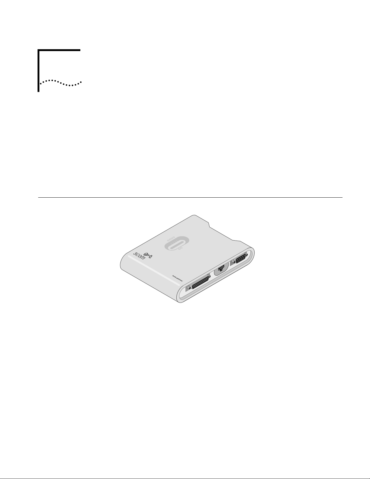
Home Ethernet
Gateway
Figure 1
Home Ethernet Gateway
The Home Ethernet Gateway features:
■
Modem and IP sharing
Connect multiple computers to a modem (cable, DSL, analog, or ISDN) or an
Ethernet router to surf the Internet.
■
Auto-sensing Ethernet switch
Network up to four computers with the 4-port auto-sensing Ethernet switch.
■
Virtual private network (VPN)
Support for multiple PPTP sessions included, allowing you to setup VPN server
and VPN clients.
■
Printer sharing
Embed a print server to allow all of the networked computers to share
one
printer.
PRINT
COM
WAN

2
C
HAPTER
1: W
ELCOME
T
O
H
OME
N
ETWORKING
■
Firewall
All unwanted packets from outside intruders are blocked to protect your
home
network.
■
DHCP server
All of the networked computers can retrieve TCP/IP settings automatically from
the gateway.
■
Web-based configuration
The gateway is configurable through any Web browser using Netscape
Communicator or Internet Explorer.
■
Access control
Different access rights can be assigned to different computers on your
home
network.
■
Virtual server
Enable access to the Web, FTP, and other services on your home network.
■
User-Definable application sensing tunnel
Attributes can be defined to support special applications requiring multiple
connections, like Internet gaming, video conferencing, and Internet telephony,
The gateway can then sense the application type and open a multi-port tunnel
for it.
■
De-Militarized Zone (DMZ) host
Fully expose one of the computers on your network to the Internet. This
function is used when special application sensing tunnel feature is insufficient
to allow an application to function correctly.
Kit Contents
■
Home Ethernet Gateway
■
Installation CD-ROM
■
Power cord and power adapter
■
Fast Ethernet cables (2)
Using This Guide
The rest of this user guide contains detailed information about your gateway and
how to connect it to your home network and the Internet.
■
Chapter 2
familiarizes you with the front, rear, top, and left panels of the
gateway, including information concerning LEDs and ports.
■
Chapter 3
explains the procedure involved in setting up your computers to
connect to the gateway.
■
Chapter 4
is an overview of the Web-based setup program.
■
Chapter 5
explains how to set up the printer sharing option.
■
Appendix A
details console mode, in which you can change the password of
the gateway if your forget it and configure other settings.
■
The
Glossary
provides devinition for key terms concerning the installation and
operation of the gateway.
2
H
ARDWARE
I
NSTALLATION
This chapter describes the panel layout of the Home Network Gateway, as well as
detailing the hardware installation procedure.
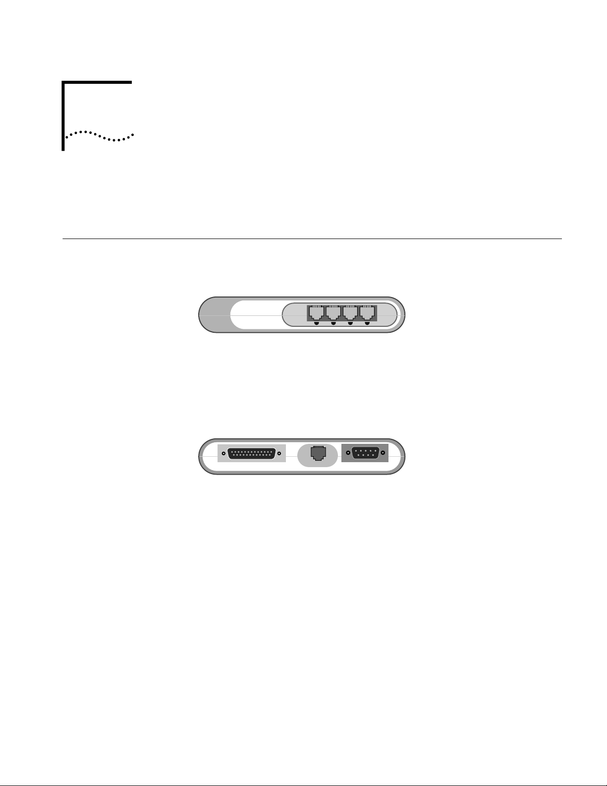
Panel Layout
Front Panel The front panel of the gateway contains 4 Ethernet ports.
Rear Panel The rear panel of the gateway contains three ports: the PRINT port, the WAN port,
and the COM port.
Ports 1 - 4 These ports function as your Ethernet switch. After you connect the devices to
these ports, (including computers, hubs, etc.), they can be networked together,
and you can share files between the computers on your home network.
1 2 3 4
PRINT Parallel port connector (25-pin D-type female). This is where you will connect the
shared printer.
WAN WAN port (RJ-45). This is where you will connect to your cable or DSL modem.
COM Serial port connector (9-pin D-type male). This is where you will connect your
analog or ISDN modem.
PRINT COM
WAN
4 CHAPTER 2: HARDWARE INSTALLATION
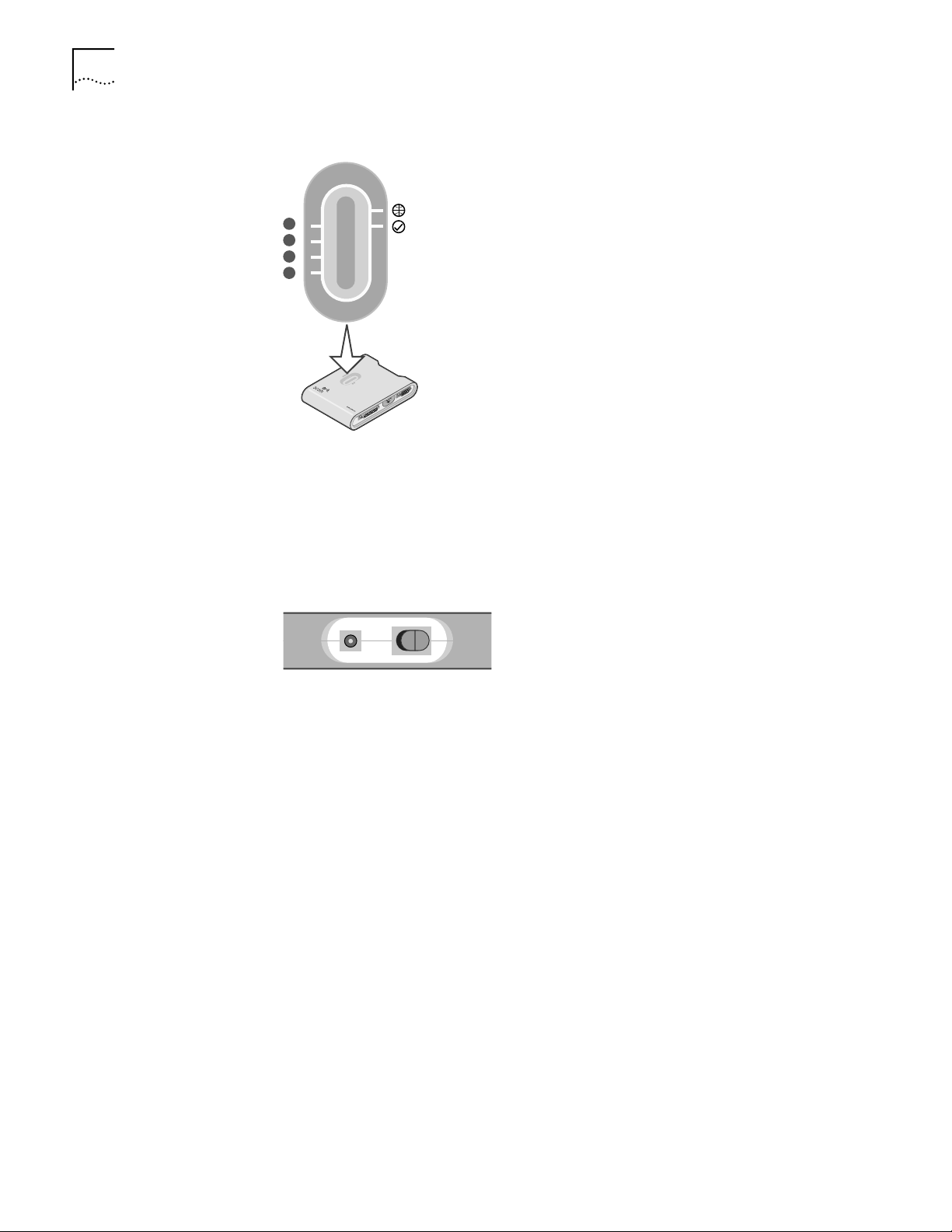
Top Panel The top panel of the gateway contains 6 LEDs.
l
Left Side Panel
Installation
Requirements
The gateway can be positioned in any convenient place in your office or home.
Follow these guidelines to ensure a troublefree installation:
■ Place the gateway on a flat horizontal surface.
■ Keep the gateway away from any sources of heat.
■ Do not place the gateway in a dusty or wet environment.
Be sure to turn off the power, remove the power cord from the outlet, and keep
your hands dry when connecting other devices to the gateway.
Ethernet Ports (1-4) The Ethernet port LEDs (green) will flicker when the corresponding port
is sending or receiving data.
WAN (globe icon) The WAN port LED (green) will flicker when the WAN port is sending or
receiving data.
Status (checkmark
icon)
The Status LED will flash once per second to indicate that the gateway
is functioning correctly.
1
2
3
4
PRINT
COM
WAN
Power connector (1) Plug the included power adapter into this connector. Use only the
power adapter that came with the gateway.
Power switch (2) Turns the power to the gateway on and off.
Hardware Installation 5
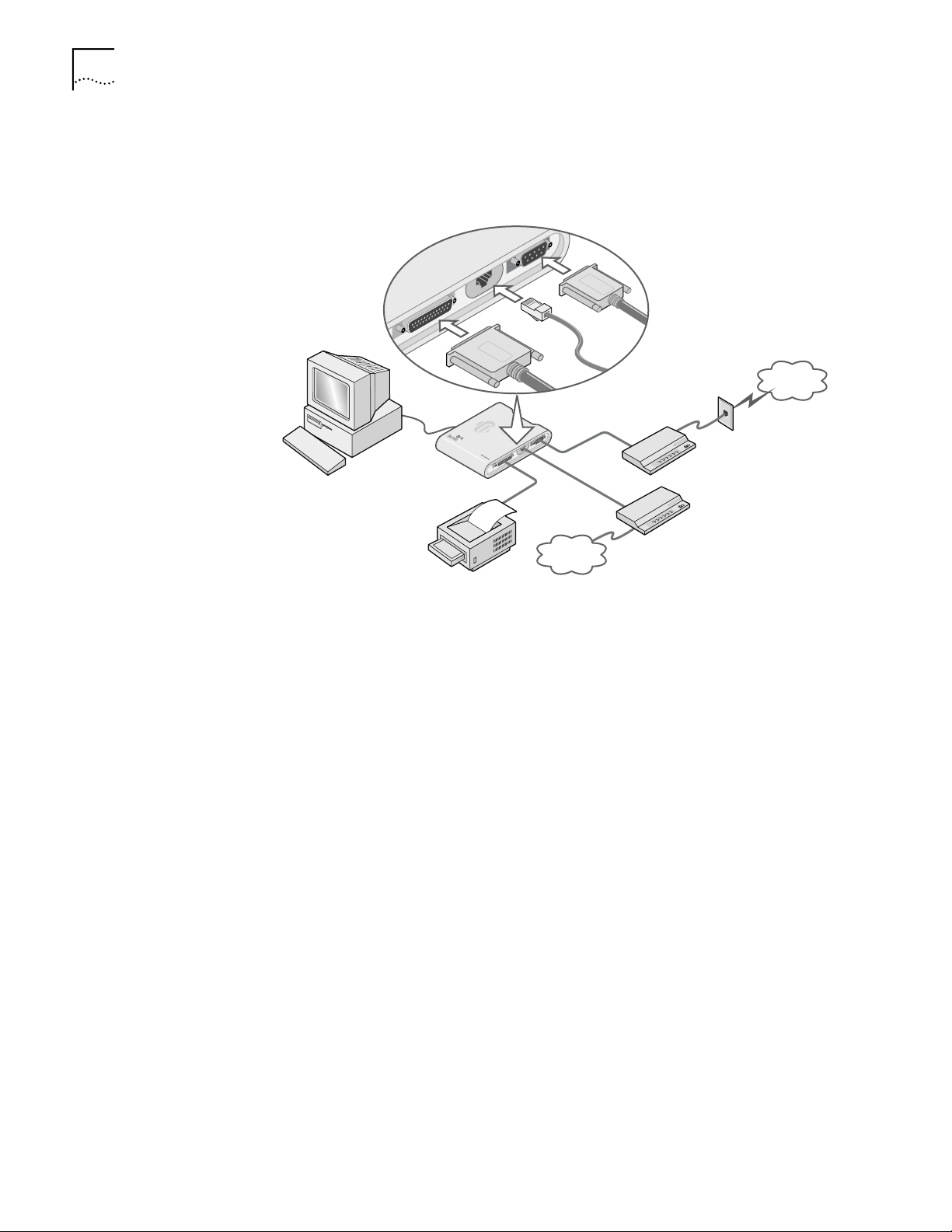
Hardware Installation This section details the cable connection procedures for the Home Ethernet
Gateway.
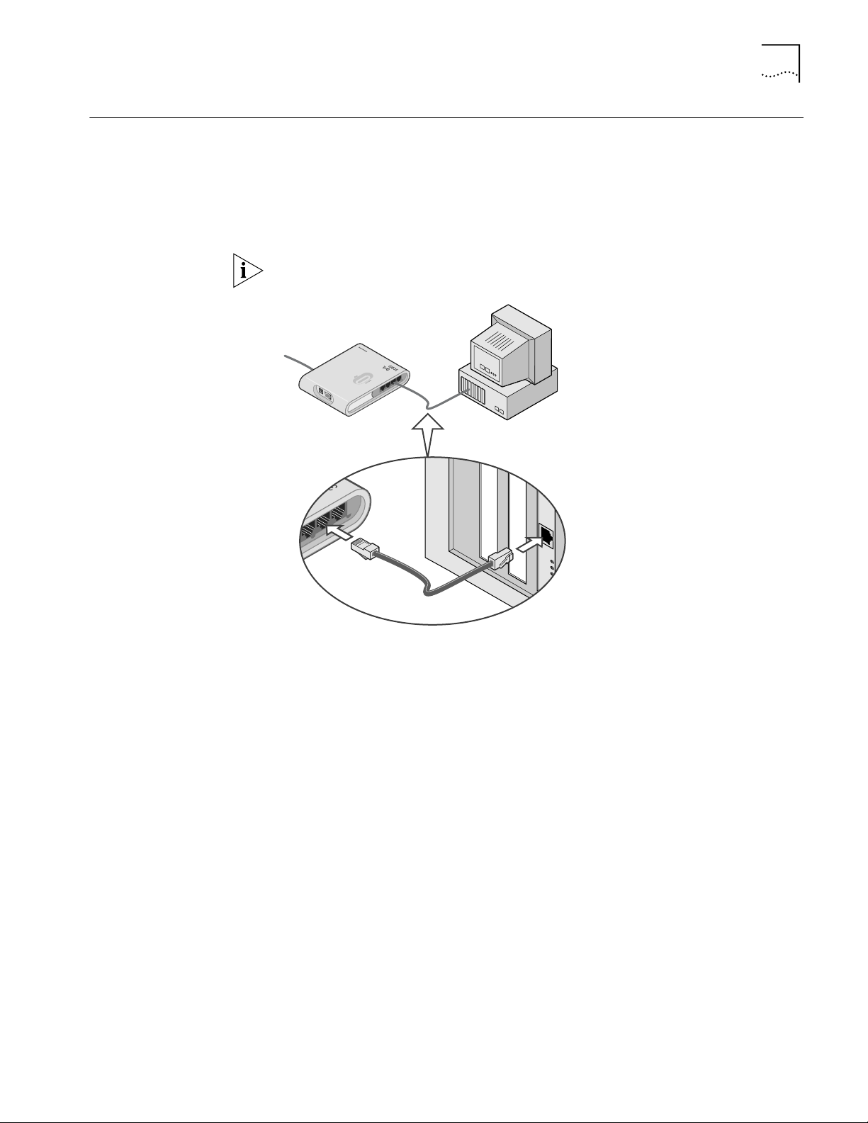
Computer Connection To create your home network, connect an Ethernet cable from the Ethernet port
of your computers to one of the Ethernet ports of the gateway, as shown in the
figure, below.
All networked computers must have Ethernet networking capabilities to connect
to the gateway.
Modem Connection There are two ways to connect modems to the gateway: using the WAN port (if
you are using a cable or DSL modem), or the COM port (if you are using an analog
or ISDN modem)
Cable or DSL Modem Connection
To connect a cable or DSL modem to the gateway, use one of the included
Ethernet cables to connect the WAN port of the gateway to your modem, as
shown in the figure below. See your cable or DSL modem documentation for
more details.
1
2
3
4
1
2
3
4
234
2
3
4
6 CHAPTER 2: HARDWARE INSTALLATION
Analog or ISDN Modem Connection
To connect an analog or ISDN modem to the gateway, use a COM cable to
connect the COM port of the gateway to your modem, as shown in the figure
below. See your analog or ISDN modem documentation for more details.
Printer Connection To connect a printer to the gateway, connect the printer cable to the PRINT port of
the gateway, as shown in the figure, above.
To use your gateway as a print server, allowing you to share one printer across
your home network, see Chapter 5 of this user manual for more details.
Power To supply power to the gateway, insert the power adapter plug in the power
connector of the gateway (see “Left Side Panel” on page 4). Then, power up the
devices of your home network in the following order:
■ Modem
■ Home Ethernet Gateway
■ Other devices (computers, printer, etc.)
Self-Test Phase
Once the gateway is powered up, it will automatically enter self-test phase. When
it is in self-test phase, the WAN and Status LEDs (see “Top Panel” on page 4) will
illuminate for about 5 seconds, and then flash three times to indicate that the
self-test has finished. Finally, the Status LED will flash once per second to indicate
that the gateway is operating normally.
Internet
P
RI
NT
C
O
M
WA
N
Analog or
ISDN modem
Cable or
DSL modem
Internet
PRINT
COM
W
A
N
Printer

3
NETWORK SETTINGS
This chapter explains how to configure the network settings of the computers on
your home network running Windows 95, 98, and NT 4.0, and Macintosh
operating systems.
Network Settings The default IP address of this product is 192.168.2.1, and the default subnet mask
IP address is 255.255.255.0. These addresses can be changed, but these default
values are used throughout this manual.
TCP/IP Settings with
Internet Sharing
If you want to set up the computers on your home network to share your Internet
connection
Windows 95, 98, and NT 4.0
1 Click Start and choose Settings, then Control Panel.
2 Double-click Network, and then select Configuration.
3 Scroll down the List window and select the TCP/IP option for the network card
that corresponds to your network interface card. For more details, see the
documentation that came with your network card.
4 Click Properties to set the TCP/IP protocol for the IP Sharer. Choose one of the
following options:
a To obtain an IP address automatically:
■ Select IP Address, and then select Obtain an IP address automatically.
■ Select DNS Configuration, and then select Disable DNS.
b To configure an IP address manually:
■ Select IP Address and then Specify an IP address. Since the default IP
address of the gateway is 192.168.2.1, enter
192.168.2.x (where x is a
value from 2 to 100) in the IP Address field. Enter
255.255.255.0 in the
Subnet Mask field.
■ Select Gateway, and then enter the IP address of the gateway (the default IP
address is 192.168.2.1) in the New Gateway field. Click Add.
■ Select DNS Configuration, and then enter the DNS values provided by your
ISP into the DNS Server Search Order field. Click Add.
5 Restart your computer.
Macintosh
1 Click the Apple Menu and select Control Panels, TCP/IP.
2 From the Configure: drop-down list, select Using DHCP Server.
3 Quit TCP/IP, and restart your computer.
Loading...