


SuperStack® 3
Switch 4200 Series
Getting Started Guide
3C17300
3C17302
3C17304
http://www.3com.com/
Part No. DUA1730-0AAA02
Published October 2002
3Com Corporation 5400 Bayfront Plaza Santa Clara, California 95052-8145
Copyright © 2002, 3Com Technologies. All rights reserved. No part of this documentation may be reproduced in any form or by any means or used to make any derivative work (such as translation, transformation, or adaptation) without written permission from 3Com Technologies.
3Com Technologies reserves the right to revise this documentation and to make changes in content from time to time without obligation on the part of 3Com Technologies to provide notification of such revision or change.
3Com Technologies provides this documentation without warranty, term, or condition of any kind, either implied or expressed, including, but not limited to, the implied warranties, terms or conditions of merchantability, satisfactory quality, and fitness for a particular purpose. 3Com may make improvements or changes in the product(s) and/or the program(s) described in this documentation at any time.
If there is any software on removable media described in this documentation, it is furnished under a license agreement included with the product as a separate document, in the hard copy documentation, or on the removable media in a directory file named LICENSE.TXT or !LICENSE.TXT. If you are unable to locate a copy, please contact 3Com and a copy will be provided to you.
UNITED STATES GOVERNMENT LEGEND
If you are a United States government agency, then this documentation and the software described herein are provided to you subject to the following:
All technical data and computer software are commercial in nature and developed solely at private expense. Software is delivered as “Commercial Computer Software” as defined in DFARS 252.227-7014 (June 1995) or as a “commercial item” as defined in FAR 2.101(a) and as such is provided with only such rights as are provided in 3Com’s standard commercial license for the Software. Technical data is provided with limited rights only as provided in DFAR 252.227-7015 (Nov 1995) or FAR 52.227-14 (June 1987), whichever is applicable. You agree not to remove or deface any portion of any legend provided on any licensed program or documentation contained in, or delivered to you in conjunction with, this User Guide.
Unless otherwise indicated, 3Com registered trademarks are registered in the United States and may or may not be registered in other countries.
3Com, the 3Com logo and SuperStack are all registered trademarks of 3Com Corporation.
Novell and NetWare are registered trademarks of Novell Incorporated.
Adobe and Acrobat are registered trademarks of Adobe Systems Incorporated.
All other company and product names may be trademarks of the respective companies with which they are associated.
Environmental Statement
It is a 3Com policy to be environmentally friendly in all operations. This manual is printed on paper that comes from sustainable, managed European forests. The production process for making the pulp has a reduced AOX level (adsorbable organic halogen) resulting in elemental chlorine-free paper.
The paper is fully biodegradable and recyclable.

CONTENTS
ABOUT THIS GUIDE
Conventions 8
Related Documentation 9
Accessing Online Documentation 10
Product Registration 10
Documentation Comments 10
1INTRODUCING THE
SUPERSTACK 3 SWITCH 4200 SERIES
|
About the Switch 4200 Series |
12 |
|
|
||
|
Summary of Hardware Features |
12 |
|
|||
|
Switch 4200 Series — Front View Detail |
13 |
||||
|
10BASE-T/ 100BASE-TX Ports 14 |
|
||||
|
10/100/1000BASE-T Ports |
14 |
|
|
||
|
GBIC Ports |
14 |
|
|
|
|
|
LEDs 15 |
|
|
|
|
|
|
Switch 4200 Series — Rear View Detail |
17 |
||||
|
Power Socket |
17 |
|
|
|
|
|
Redundant Power System Socket |
17 |
|
|||
|
Console Port |
17 |
|
|
|
|
|
Default Settings |
18 |
|
|
|
|
|
|
|
|
|
||
2 INSTALLING THE SWITCH |
|
|
|
|||
|
Package Contents 20 |
|
|
|
|
|
|
Choosing a Suitable Site |
20 |
|
|
|
|
|
Rack-mounting |
21 |
|
|
|
|
|
Placing Units On Top of Each Other |
23 |
|
|||
|
Stacking Units |
23 |
|
|
|
|
|
The Power-up Sequence |
24 |
|
|
|
|
|
Powering-up the Switch 4200 Series |
24 |
||||
|
Checking for Correct Operation of LEDs |
24 |
|
||||||
|
Connecting a Redundant Power System |
25 |
|
||||||
|
Choosing the Correct Cables |
25 |
|
|
|
|
|||
|
Choosing the correct Fiber cables |
26 |
|
|
|||||
|
GBIC Operation |
27 |
|
|
|
|
|
|
|
|
Approved GBIC Transceivers |
27 |
|
|
|
|
|||
|
Inserting a GBIC Transceiver |
27 |
|
|
|
|
|||
|
|
|
|
|
|||||
3 SETTING UP FOR MANAGEMENT |
|
|
|
||||||
|
Setting Up Overview |
32 |
|
|
|
|
|
|
|
|
IP Configuration 33 |
|
|
|
|
|
|
||
|
Preparing for Management |
|
34 |
|
|
|
|
||
|
Manually Configuring IP Information |
35 |
|
|
|||||
|
Connecting to a Front Panel Port |
35 |
|
|
|||||
|
Connecting to the Console Port |
38 |
|
|
|
||||
|
Viewing Automatically Configured IP Information |
42 |
|||||||
|
Using 3Com Network Supervisor |
42 |
|
|
|
||||
|
Connecting to the Console Port |
42 |
|
|
|
||||
|
Methods of Managing a Switch |
45 |
|
|
|
|
|||
|
Command Line Interface Management |
|
45 |
|
|||||
|
Web Interface Management |
46 |
|
|
|
|
|||
|
SNMP Management |
46 |
|
|
|
|
|
|
|
|
Setting Up Command Line Interface Management |
47 |
|||||||
|
CLI Management via the Console Port |
|
47 |
|
|||||
|
CLI Management over the Network |
47 |
|
||||||
|
Setting Up Web Interface Management |
48 |
|
||||||
|
Pre-requisites |
48 |
|
|
|
|
|
|
|
|
Web Management Over the Network |
|
49 |
|
|||||
|
Setting Up SNMP Management |
49 |
|
|
|
|
|||
|
Pre-requisites |
50 |
|
|
|
|
|
|
|
|
Default Users and Passwords |
50 |
|
|
|
|
|||
|
Changing Default Passwords |
50 |
|
|
|
|
|||
|
|
|
|
|
|
|
|
|
|
4 PROBLEM SOLVING |
|
|
|
|
|
|
|
||
|
Solving Problems Indicated by LEDs |
54 |
|
|
|
||||
|
Solving Hardware Problems |
55 |
|
|
|
|
|
||
|
Solving Communication Problems |
55 |
|
|
|
||||
|
Solving Stack Formation Problems |
56 |
||||
|
Solving Software Upgrade Problems |
57 |
||||
A |
|
|
|
|||
SAFETY INFORMATION |
|
|
||||
|
Important Safety Information |
60 |
|
|||
|
L’information de Sécurité Importante |
62 |
||||
|
Wichtige Sicherheitsinformationen |
64 |
||||
B |
|
|
|
|
|
|
PIN-OUTS |
|
|
|
|
|
|
|
Null Modem Cable |
67 |
|
|
|
|
|
PC-AT Serial Cable |
67 |
|
|
|
|
|
Modem Cable 68 |
|
|
|
|
|
|
RJ-45 Pin Assignments |
68 |
|
|
||
|
1000BASE-T RJ-45 Pin Assignments |
69 |
||||
C |
|
|
||||
TECHNICAL SPECIFICATIONS |
|
|||||
|
Switch 4226T |
|
|
|
|
|
|
(3C17300) |
71 |
|
|
|
|
|
Switch 4250T |
|
|
|
|
|
|
(3C17302) |
73 |
|
|
|
|
|
Switch 4228G |
|
|
|
|
|
|
(3C17304) |
74 |
|
|
|
|
D |
|
|
|
|
||
TECHNICAL SUPPORT |
|
|
|
|||
|
Online Technical Services |
75 |
|
|
||
|
World Wide Web Site |
75 |
|
|
||
|
3Com Knowledgebase Web Services 76 |
|||||
|
3Com FTP Site |
76 |
|
|
|
|
|
Support from Your Network Supplier |
76 |
||||
|
Support from 3Com |
77 |
|
|
||
|
Internet Support |
77 |
|
|
||
|
Telephone Support |
77 |
|
|
||
|
Returning Products for Repair |
79 |
|
|||

INDEX
REGULATORY NOTICES

ABOUT THIS GUIDE
This guide provides all the information you need to install and use a SuperStack® 3 Switch 4200 in its default state.
This guide is intended for use with all Switch 4200 Series models:
■Switch 4226T (3C17300) — 24 10BASE-T/100BASE-TX ports, 2 10/100/1000BASE-T ports
■Switch 4250T (3C17302) — 48 10BASE-T/100BASE-TX ports, 2 10/100/1000BASE-T ports
■Switch 4228G (3C17304) — 24 10BASE-T/100BASE-TX ports, 2 10/100/1000BASE-T ports and 2 GBIC ports
All procedures described in this guide apply to all models except where stated.
The guide is intended for use by network administrators who are responsible for installing and setting up network equipment; consequently, it assumes a basic working knowledge of LANs (Local Area Networks).
If the information in the release notes that are shipped with your product differ from the information in this guide, follow the instructions in the release notes.
Most user guides and release notes are available in Adobe Acrobat Reader Portable Document Format (PDF) or HTML on the 3Com World Wide Web site:
http://www.3com.com/
8 ABOUT THIS GUIDE
Conventions |
Table 1 and Table 2 list conventions that are used throughout this guide. |
||||
|
Table 1 |
Notice Icons |
|
|
|
|
|
|
|
|
|
|
Icon |
Notice Type |
Description |
||
|
|
|
|
||
|
|
Information note Information that describes important features or |
|||
|
|
|
|
instructions |
|
|
|
Caution |
|
Information that alerts you to potential loss of data or |
|
|
|
|
|
potential damage to an application, system, or device |
|
|
|
Warning |
|
Information that alerts you to potential personal injury |
|
|
|
|
|
||
|
Table 2 |
Text Conventions |
|||
|
|
|
|
||
|
Convention |
Description |
|||
|
|
|
|||
|
Screen displays |
This typeface represents information as it appears on the |
|
||
|
|
|
screen. |
||
|
Syntax |
|
The word “syntax” means that you must evaluate the syntax |
|
|
|
|
|
provided and then supply the appropriate values for the |
||
|
|
|
placeholders that appear in angle brackets. Example: |
||
|
|
|
To change your password, use the following syntax: |
||
|
|
|
|
system password <password> |
|
|
|
|
In this example, you must supply a password for <password>. |
||
|
|
|
|||
|
Commands |
The word “command” means that you must enter the |
|
||
|
|
|
command exactly as shown and then press Return or Enter. |
||
|
|
|
Commands appear in bold. Example: |
||
|
|
|
To display port information, enter the following command: |
||
|
|
|
|
bridge port detail |
|
|
The words “enter” |
When you see the word “enter” in this guide, you must type |
|
||
|
and “type” |
something, and then press Return or Enter. Do not press |
|||
|
|
|
Return or Enter when an instruction simply says “type.” |
||
|
|
|
|||
|
Keyboard key names |
If you must press two or more keys simultaneously, the key |
|
||
|
|
|
names are linked with a plus sign (+). Example: |
||
|
|
|
|
Press Ctrl+Alt+Del |
|
|
|
|
|||
|
Words in italics |
Italics are used to: |
|
||
|
|
|
■ |
Emphasize a point. |
|
|
|
|
■ Denote a new term at the place where it is defined in the |
||
|
|
|
|
text. |
|
■ Identify menu names, menu commands, and software button names. Examples:
From the Help menu, select Contents.
Click OK.

Related Documentation |
9 |
Related |
In addition to this guide, each Switch documentation set includes the |
Documentation |
following: |
|
■ SuperStack 3 Switch Implementation Guide |
|
This guide contains information on the features supported by your |
|
Switch and how they can be used to optimize your network. It is |
|
supplied in PDF format on the CD-ROM that accompanies the Switch. |
|
■ SuperStack 3 Switch Management Quick Reference Guide |
|
This guide contains: |
|
■ a list of the software features supported by the Switch. |
|
■ a summary of the web interface and command line interface |
|
commands for the Switch. |
|
■ SuperStack 3 Switch Management Interface Reference Guide |
|
This guide provides detailed information about the web interface and |
|
command line interface that enable you to manage the Switch. It is |
|
supplied in HTML format on the CD-ROM that accompanies the |
|
Switch. |
|
■ Release Notes |
|
These notes provide information about the current software release, |
|
including new features, modifications, and known problems. |
|
There are other publications you may find useful, such as: |
|
■ Documentation accompanying the Advanced Redundant Power |
|
system. |
|
■ Documentation accompanying 3Com Network Supervisor. This is |
|
supplied on the CD-ROM that accompanies the Switch. |

10 ABOUT THIS GUIDE
Accessing Online The CD-ROM supplied with your Switch contains the following online Documentation documentation:
■SuperStack 3 Switch Implementation Guide (PDF format)
■SuperStack 3 Switch Management Interface Reference Guide (HTML format)
1To access the documentation insert the CD-ROM into your CD-ROM drive. If your PC has auto-run enabled, a splash screen will be displayed automatically.
2Select the Documentation section from the contents page.
If the online documentation is to be accessed from a local drive or server, you will need to access the CD-ROM contents via the root directory and copy the files from the CD-ROM to a suitable directory.
■The HTML Reference Guide is stored in the Docs/reference directory on the CD-ROM. The documentation is accessed using the contents.htm file.
■The PDF Implementation Guide is stored in the Docs/implementation directory of the CD-ROM.
|
3Com recommends that you copy the Docs/reference directory as a |
|
whole to maintain the structure of the files. |
|
|
Product |
You can register your SuperStack 3 Switch 4200 on the 3Com Web site: |
Registration |
http://3com.com/register |
|
|
Documentation |
Your suggestions are very important to us. They will help make our |
Comments |
documentation more useful to you. Please e-mail comments about this |
|
document to 3Com at: |
|
pddtechpubs_comments@3com.com |
|
Please include the following information when commenting: |
|
■ Document title |
|
■ Document part number (on the title page) |
|
■ Page number (if appropriate) |
|
Example: |
|
Part Number DUA 1730-0AAA0x |
|
SuperStack 3 Switch 4200 Series Getting Started Guide |
|
Page 21 |
1 |
INTRODUCING THE |
SUPERSTACK 3 SWITCH 4200 |
SERIES
This chapter contains introductory information about the Switch 4200 Series and how it can be used in your network. It covers summaries of hardware and software features and also the following topics:
■About the Switch 4200 Series
■Switch 4200 Series — Front View Detail
■Switch 4200 Series — Rear View Detail
■Default Settings

12 CHAPTER 1: INTRODUCING THE SUPERSTACK 3 SWITCH 4200 SERIES
About the Switch |
The Switch 4200 Series are stackable 10/100/1000 Mbps devices which |
||
4200 Series |
consists of: |
||
|
■ 24 or 48 10BASE-T/100BASE-TX ports |
||
|
■ |
2 |
10/100/1000BASE-T ports |
|
■ |
2 |
GBIC ports (Switch 4228G only) |
The Switch provides high-performance workgroups with a backbone to server connection. You can also add the Switch 4200 Series to any SuperStack® system as your network grows.
Summary of Table 3 summarizes the hardware features that are supported by the Hardware Features Switch 4200 Series.
Table 3 Hardware features
Feature |
Switch 4200 Series |
|
|
Addresses |
■ Up to 8000 supported |
|
■ Up to 64 permanent entries |
Auto-negotiation |
■ Supported on all ports |
|
■ Auto MDI/MDI-X |
Forwarding Modes |
Store and Forward |
Duplex Modes |
Half and full duplex on all 10/100 ports. Full duplex |
|
on 1000BASE-T ports and full duplex on GBIC ports |
Flow Control |
In full duplex operation all ports are supported |
Smart Auto-sensing |
Supported on all ports except GBIC ports which are |
|
single speed ports. |
|
Smart auto-sensing allows auto-negotiating ports to |
|
monitor and detect a high error rate on a link, or a |
|
problem in the "physical" interconnection to |
|
another port and react accordingly. |
Traffic Prioritization |
Supported (IEEE 802.ID): 2 queues per port |
Ethernet and Fast Ethernet |
Auto-negotiating 10BASE-T/100BASE-TX ports |
Ports |
|
Gigabit Ethernet |
Auto-negotiating 10/100/1000BASE-T ports |
GBIC |
Auto-negotiating GBIC ports (Switch 4228G only) |
RPS Support |
Connects to SuperStack Advanced Redundant |
|
Power System (ARPS) (3C16071, 3C16071A or |
|
3C16071B) |
Mounting |
19-inch rack or stand-alone mounting |
|
|

About the Switch 4200 Series 13
Switch 4200 Series |
|
Figure 1 Switch 4226T (3C17300) — front view |
||||||||||||||
— Front View |
|
|
|
|
|
|
|
|
|
|
||||||
Detail |
|
|
|
|
|
|
|
|
|
|
|
|
|
|
||
|
|
|
|
|
|
|
10BASE-T / 100BASE-TX |
|
|
|||||||
|
|
|
|
|
|
|
|
|
RJ-45 Ports |
|
|
|
|
|||
|
|
|
|
|
|
|
|
|
|
|
|
Unit LEDs |
Power / Self Test LED |
|||
|
|
|
|
|
|
|
|
|
|
|
|
|
||||
1 |
13 |
2 |
14 |
3 15 |
4 16 |
5 17 |
6 18 |
7 19 |
8 20 |
9 |
21 |
10 22 |
11 23 |
12 24 |
3C17300 Superstack 3 Switch 4226T |
|
Power/ |
||||||||||||||||
|
|
|
|
|
|
|
|
|
|
|
|
|
|
|
||
|
|
|
|
|
|
|
|
|
|
|
|
|
|
|
Self Test |
|
|
|
|
|
|
|
|
|
|
|
|
|
|
|
1 |
25 / Up 26 / Down |
|
2 |
|
3 |
Alert |
4 |
Unit |
Alert LED
10/100/1000BASE-T ports
Figure 2 Switch 4250T (3C17302) — front view
10BASE-T / 100BASE-TX
RJ-45 Ports
Unit LEDs |
Power / Self Test LED |
|
|
|
|
|
|
|
|
|
|
|
|
|
|
|
|
|
|
|
|
|
|
|
|
|
|
|
|
|
|
|
|
|
|
|
|
|
|
|
|
3C17302 Superstack 3 Switch 4250T |
|
|
|
||||
1 |
25 |
2 |
26 |
3 |
27 |
4 |
28 |
5 |
29 |
6 |
30 |
7 |
31 |
8 |
32 |
9 |
33 |
10 |
34 |
11 |
35 |
12 |
36 |
13 |
37 |
14 |
38 |
15 |
39 |
16 |
40 |
17 |
41 |
18 |
42 |
19 |
43 |
20 |
44 |
21 45 |
22 46 |
23 47 |
24 |
48 |
Power/ |
|
|
|
|
|
|
|
|
|
|
|
|
|
|
|
|
|
|
|
|
|
|
|
|
|
|
|
|
|
|
|
|
|
|
|
|
|
|
|
|
|
|
|
|
|
|
|
|
|
|
|
|
|
|
|
|
|
|
|
|
|
|
|
|
|
|
|
|
|
|
|
|
|
|
|
|
|
|
|
|
|
|
|
|
|
|
|
|
|
|
|
|
|
|
|
Self Test |
|
|
|
|
|
|
|
|
|
|
|
|
|
|
|
|
|
|
|
|
|
|
|
|
|
|
|
|
|
|
|
|
|
|
|
|
|
|
|
|
|
|
|
|
|
|
1 |
|
|
|
|
|
|
|
|
|
|
|
|
|
|
|
|
|
|
|
|
|
|
|
|
|
|
|
|
|
|
|
|
|
|
|
|
|
|
|
|
|
|
|
|
|
|
|
2 |
|
|
Down |
|
|
|
|
|
|
|
|
|
|
|
|
|
|
|
|
|
|
|
|
|
|
|
|
|
|
|
|
|
|
|
|
|
|
|
|
|
|
|
|
|
|
|
|
3 |
Alert |
Up |
|
|
|
|
|
|
|
|
|
|
|
|
|
|
|
|
|
|
|
|
|
|
|
|
|
|
|
|
|
|
|
|
|
|
|
|
|
|
|
|
|
|
|
|
|
|
|
||
4  Unit
Unit
49 |
|
|
|
|
|
50 |
Alert LED
10/100/1000BASE-T ports
Figure 3 Switch 4228G (3C17304) — front view
10BASE-T / 100BASE-TX
RJ-45 Ports
Power / Self Test LED
Unit LEDs
1 |
13 |
2 |
14 |
3 15 |
4 16 |
5 17 |
6 18 |
7 19 |
8 20 |
9 |
21 |
10 22 |
11 23 |
12 24 |
Power/ |
|
|
Self Test |
|
27 |
1 |
25 / Up 26 / Down |
27 |
2 |
|
|
3 |
Alert |
|
4 |
Unit |
28 |
3C17304 Superstack 3 Switch 4228G
28
Alert LED
10/100/1000BASE-T GBIC ports ports

14 CHAPTER 1: INTRODUCING THE SUPERSTACK 3 SWITCH 4200 SERIES
WARNING: RJ-45 Ports. These are shielded RJ-45 data sockets. They cannot be used as standard traditional telephone sockets, or to connect the unit to a traditional PBX or public telephone network. Only connect RJ-45 data connectors, network telephony systems, or network telephones to these sockets.
Either shielded or unshielded data cables with shielded or unshielded jacks can be connected to these data sockets.
10BASE-T/ The Switch has 24 or 48 auto-negotiating 10BASE-T/100BASE-TX ports 100BASE-TX Ports configured as Auto MDIX (cross-over). While auto-negotiation is enabled,
these ports can automatically detect whether they need to operate in MDI or MDIX mode. Alternatively, you can manually set these ports to 10BASE-T half duplex, 10BASE-T full duplex, 100BASE-TX half duplex or 100BASE-TX full duplex. The maximum segment length is 100 m (328 ft) over Category 5 twisted pair cable.
10/100/1000BASE-T The Switch has two auto-negotiating 10/100/1000BASE-T ports
Ports configured as Auto MDIX (cross-over). While auto-negotiation is enabled, these ports can automatically detect whether they need to operate in MDI or MDIX mode. These ports provide 10/100/1000 Mbps full duplex connections to other Gigabit Ethernet devices. Full duplex allows packets to be transmitted and received simultaneously which, in effect, doubles the potential throughput of a link. These ports require either straight-through or cross-over Category 5 cables with RJ-45 connectors at both ends. The maximum UTP cable length is 100 m (328 ft) over Category 5 cable.
The 10/100/1000BASE-T ports will auto-negotiate to the appropriate speed.
GBIC Ports This section applies to the SuperStack 3 Switch 4228G only.
The two GBIC ports support Category 5 twisted pair cable and fiber Gigabit Ethernet short-wave (SX), long-wave (LX) and long-haul (LH70) GBIC transceivers in any combination. This offers you the flexibility of using GBIC transceivers to provide connectivity between the Switch and remote 1000 Mbps workgroups or to create a high capacity aggregated link backbone connection.

About the Switch 4200 Series 15
Fiber GBIC's.
The default state for these ports is auto-negotiation enabled, where speed, duplex and flow control modes are negotiated. Because the speed and duplex modes are fixed by the media type, only the flow control is negotiated with the link partner. Alternatively, auto-negotiation can be disabled and the flow control setting can be manually configured.
1000BaseT GBIC's
These ports will auto-negotiate to 1000BASE-T, full duplex only. Although it is not possible to disable auto-negotiation it is possible to change the advertised capabilities for flow control support, effectively enabling or disabling flow control.
LEDs Table 4 lists LEDs visible on the front of the Switch, and how to read their status according to color. For information on using the LEDs for problem solving, see “Solving Problems Indicated by LEDs” on page 54.
It is not possible to determine the duplex mode from the LEDs. For more detailed information, refer to the “SuperStack 3 Switch Management Interface Reference Guide” on the CD-ROM that is supplied with the Switch.
Table 4 |
LED behavior |
|
|
|
|
LED |
Color |
Indicates |
|
||
Port Status LEDs 10BASE-T/100BASE-TX ports |
||
|
Green |
A 100 Mbps link is present and the port is enabled. |
|
Green flashing |
Packets are being transmitted/received on the port. |
|
Yellow |
A 10 Mbps link is present and the port is enabled. |
|
Yellow flashing |
Packets are being transmitted/received on the port. |
|
Green / Yellow |
A 10 or 100 Mbps link is present, but the port is disabled. |
|
alternating |
|
|
Off |
No link is present. |
Port Status LEDs GBIC ports |
||
|
Green |
A 1000 Mbps link is present and the port is enabled. |
|
Green flashing |
Packets are being transmitted/received on the port. |
Port Status LEDs 10/100/1000BASE-T ports |
||
|
Green |
A 1000 Mbps link is present and the port is enabled. |
(continued) |
|
|

16 CHAPTER 1: INTRODUCING THE SUPERSTACK 3 SWITCH 4200 SERIES
LED |
Color |
Indicates |
|
|
|
|
Green flashing |
Packets are being transmitted/received on the port. |
|
Yellow |
A 10 or 100 Mbps link is present and the port is enabled. |
|
Yellow flashing |
Packets are being transmitted/received on the port. |
|
Green / Yellow |
A 10, 100 or 1000 Mbps link present but disabled. |
|
alternating |
|
|
Off |
No link is present. |
Unit LEDs |
|
|
1–4 |
Green |
When the Switch forms a stack with other Switch 4200 |
|
|
Series units the LED indicates the position of the unit in the |
|
|
stack and that a link is present. Unit LED number 1 can also |
|
|
indicate a stand-alone Switch. |
|
Off |
The Switch initialization process is not complete. |
Power/Self Test LED |
|
|
|
Green |
The Switch is powered-up and operating normally. |
|
Green flashing |
The Switch is either downloading software or is initializing |
|
|
(which includes running a Power On Self Test). |
|
Yellow |
The Switch has failed its Power On Self Test. |
|
|
Refer to Chapter 4 Solving Problems Indicated by LEDs. |
|
Off |
The Switch is not receiving power or there is a fault with the |
|
|
Power Supply Unit. |
Alert LED |
|
|
|
Green flashing |
The Switch Alert LED has been configured via the CLI or Web |
|
|
Interface to flash. |
|
Off |
The Switch Alert LED has been configured via the CLI or Web |
|
|
Interface to be off (Default state). |
|
|
|
About the Switch 4200 Series 17
Switch 4200 Series |
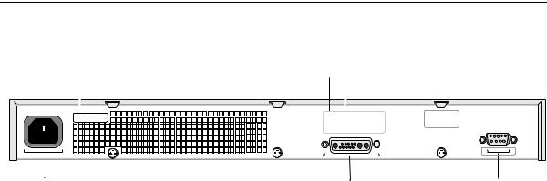
Figure 4 Switch 4200 Series — rear view |
— Rear View Detail |
|
|
Supply Data Warning Label |
Console (max) 19200,8,1,N
|
|
|
|
|
|
|
Redundant Power System Socket |
|
Console Port |
|
|
|
|
|
|
|
|
||
|
|
|
|
|
|
|
|
||
|
|
|
|
|
|
|
|
||
Power Socket |
|
|
|||||||
Power Socket The Switch automatically adjusts its power setting to any supply voltage in the range 90-240 VAC.
Redundant Power To protect against internal power supply failure, you can use this socket System Socket to connect a Switch 4200 to a SuperStack Advanced Redundant Power
System (RPS). See “Connecting a Redundant Power System” on page 25.
Console Port The console port allows you to connect a terminal and perform remote or local out-of-band management. The console port uses a standard null modem cable and is set to auto-baud, 8 data bits, no parity and 1 stop bit.

18 CHAPTER 1: INTRODUCING THE SUPERSTACK 3 SWITCH 4200 SERIES
Default Settings Table 5 shows the default settings for the Switch 4200 Series:
Table 5 Default Settings
Feature |
Switch 4200 Series |
|
|
Automatic IP Configuration |
Enabled |
Port Status |
Enabled |
Port Speed |
All ports are auto-negotiated |
Duplex Mode |
All ports are auto-negotiated |
Flow Control |
■ Enabled in half duplex |
|
■ Auto-negotiated in full duplex |
Broadcast Storm Control |
Enabled |
Virtual LANs (VLANs) |
All ports belong to the untagged Default VLAN |
|
(VLAN 1) with 802.1Q learning operational |
IP Multicast Filtering |
Filtering enabled |
Rapid Spanning Tree Protocol |
Enabled |
Fast Start: |
Enabled on all ports |
RMON Alarm |
Enabled |
Smart Auto-Sensing |
Enabled |
LACP |
(10/100/1000BASE-T ports and GBIC ports only) |
|
Enabled |
Quality of Service (QoS) |
All ports prioritize NBX VoIP IP. |
|
All ports set to “best effort” for all other traffic. |
|
|
If you initialize a Switch unit by selecting System > Control > Initialize in the Web interface or by entering system control initialize in the Command Line Interface, the following settings are retained to allow you to connect to and manage the Switch:
■IP Address
■Subnet Mask
■Default Router
2 |
INSTALLING THE SWITCH |
|
This chapter contains the information you need to install and set up the Switch 4200 Series. It covers the following topics:
■Package Contents
■Choosing a Suitable Site
■Rack-mounting
■Placing Units On Top of Each Other
■The Power-up Sequence
■GBIC Operation
WARNING: Safety Information. Before installing or removing any components from the Switch 4200 Series or carrying out any maintenance procedures, you must read the safety information provided in Appendix A of this guide.
AVERTISSEMENT: Consignes de sécurité. Avant d'installer ou d'enlever tout composant du Switch 4200 ou d'entamer une procédure de maintenance, lisez les informations relatives à la sécurité qui se trouvent dans l'Appendice A de ce guide.
VORSICHT: Sicherheitsinformationen. Bevor Sie Komponenten aus dem Switch 4200 entfernen oder dem Switch 4200 hinzufuegen oder Instandhaltungsarbeiten verrichten, lesen Sie die Sicherheitsanweisungen, die in Appendix A (Anhang A) in diesem Handbuch aufgefuehrt sind.

20 CHAPTER 2: INSTALLING THE SWITCH
Package Contents |
■ |
Switch unit |
|
■ |
CD-ROM |
|
■ Getting Started Guide (this guide) |
|
|
■ Management Quick Reference Guide |
|
|
■ |
Release Notes |
|
■ |
Unit Information Labels |
|
■ |
Warranty Information |
|
■ |
Power Cord |
|
■ 2 x Mounting brackets |
|
|
■ |
4 x Screws |
|
■ 4 x Rubber feet |
|
|
|
|
Choosing a Suitable |
The Switch is suited for use on a desktop, either free standing or |
|
Site |
mounted in a standard 19-inch equipment rack. Alternatively, the Switch |
|
|
can be mounted in a wiring closet or equipment room, as an aggregator |
|
for other Hubs and Switches. A rack-mounting kit containing two mounting brackets is supplied with the Switch.
CAUTION: Ensure that the ventilation holes are not obstructed.
When deciding where to position the Switch, ensure that:
■Cabling is located away from:
■sources of electrical noise such as radios, transmitters and broadband amplifiers.
■power lines and fluorescent lighting fixtures
■The Switch is accessible and cables can be connected easily.
■Water or moisture cannot enter the case of the Switch.
■Air-flow is not restricted around the Switch or through the vents in the side of the Switch. 3Com recommends that you provide a minimum of 25mm (1in.) clearance.
■Air temperature around the Switch does not exceed 40 °C (104 °F).
If the Switch is installed in a 19-inch rack or closed assembly its local air temperature may be greater than room ambient temperature.
Rack-mounting 21
■ The air is as free from dust as possible.
■ The switch is situated away from sources of conductive (electrical) dust, for example, laser printers.
|
■ The unit is installed in a clean, air conditioned environment. |
|
■ The AC supply used by the switch is separate to that used by units |
|
that generate high levels of AC noise, for example, air-conditioning |
|
units and laser printers. |
|
■ No more than eight Switch units are placed on top of one another, if |
|
the units are free-standing. |
|
|
Rack-mounting |
The Switch 4200 Series are 1U high and will fit in most standard 19-inch |
|
racks. |
|
CAUTION: Disconnect all cables from the Switch before continuing. |
|
Remove all self adhesive pads from the underside of the Switch if they |
|
have been fitted. |
|
To rack-mount your Switch: |
|
1 Place the Switch the right way up on a hard flat surface, with the front |
|
facing towards you. |
|
2 Locate a mounting bracket over the mounting holes on one side of the |
|
Switch, as shown in Figure 5. |
22 CHAPTER 2: INSTALLING THE SWITCH
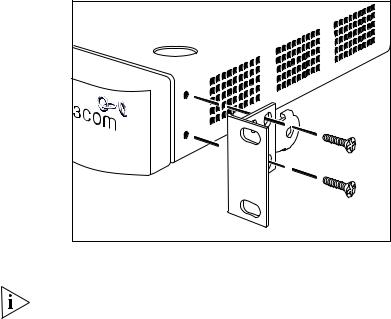
Figure 5 Fitting a bracket for rack-mounting
3Insert the two screws and tighten with a suitable screwdriver.
You must use the screws supplied with the mounting brackets. Damage caused to the unit by using incorrect screws invalidates your warranty.
4Repeat steps 2 and 3 for the other side of the Switch.
5Insert the Switch into the 19-inch rack and secure with suitable screws (not provided). Ensure that ventilation holes are not obstructed.
6Connect network cabling.
7Finally place a unit information label on the unit in an easily accessible position. The unit information label shows the following:
■The 3Com product name of the Switch
■The 3Com 3C number of the Switch
■The unique MAC address (Ethernet address) of the Switch
■The serial number of the Switch
You may need this information for fault reporting purposes.
Placing Units On Top of Each Other 23
Placing Units On If the Switch units are free-standing, up to eight units can be placed one Top of Each Other on top of the other. If you are mixing a variety of SuperStack® 3 Switch
and Hub units, the smaller units must be positioned at the top.
|
If you are placing Switch units one on top of the other, you must use the |
|
self-adhesive rubber pads supplied. Apply the pads to the underside of |
|
each Switch, sticking one in the marked area at each corner. Place the |
|
Switch units on top of each other, ensuring that the pads of the upper |
|
unit line up with the recesses of the lower unit. |
|
|
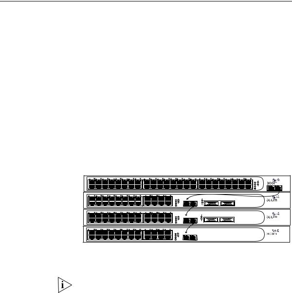
Stacking Units |
Up to four Switch 4200 Series units can be stacked together and then |
|
treated as a single manageable unit with one IP address. Any |
|
combination of Switch 4200 Series units is allowed in a single stack. The |
|
units are connected together via the 10/100/1000BASE-T ports on the |
|
front of the unit as shown in Figure 6. Starting from the base of the stack, |
|
the port marked with ‘up’ is connected to the port marked with ‘down’ |
|
on the unit above. Cable lengths of between 14 cm (5.5 in) and |
|
100 m (328 ft) can be used for stacking. |
Figure 6 Stacking example
|
|
|
|
|
|
|
|
|
|
|
|
|
|
|
|
|
|
|
|
|
|
|
|
|
|
|
|
|
|
|
|
|
|
|
|
|
|
|
|
3C17302 Superstack 3 Switch 4250T |
|
|
|
||||
1 |
25 |
2 |
26 |
3 |
27 |
4 |
28 |
5 |
29 |
6 |
30 |
7 |
31 |
8 |
32 |
9 |
33 |
10 |
34 |
11 |
35 |
12 |
36 |
13 |
37 |
14 |
38 |
15 |
39 |
16 |
40 |
17 |
41 |
18 |
42 |
19 |
43 |
20 |
44 |
21 45 |
22 46 |
23 47 |
24 |
48 |
Power/ |
|
|
|
|
|
|
|
|
|
|
|
|
|
|
|
|
|
|
|
|
|
|
|
|
|
|
|
|
|
|
|
|
|
|
|
|
|
|
|
|
|
|
|
|
|
|
|
Self Test |
|
|
|
|
|
|
|
|
|
|
|
|
|
|
|
|
|
|
|
|
|
|
|
|
|
|
|
|
|
|
|
|
|
|
|
|
|
|
|
|
|
|
|
|
|
|
1 |
|
|
|
|
|
|
|
|
|
|
|
|
|
|
|
|
|
|
|
|
|
|
|
|
|
|
|
|
|
|
|
|
|
|
|
|
|
|
|
|
|
|
|
|
|
|
|
2 |
|
Up |
Down |
|
|
|
|
|
|
|
|
|
|
|
|
|
|
|
|
|
|
|
|
|
|
|
|
|
|
|
|
|
|
|
|
|
|
|
|
|
|
|
|
|
|
|
|
3 |
Alert |
||
|
|
|
|
|
|
|
|
|
|
|
|
|
|
|
|
|
|
|
|
|
|
|
|
|
|
|
|
|
|
|
|
|
|
|
|
|
|
|
|
|
|
|
|
|
|||
|
|
|
|
|
|
|
|
|
|
|
|
|
|
|
|
|
|
|
|
|
|
|
|
|
|
|
|
|
|
|
|
|
|
|
|
|
|
|
|
|
|
|
|
4 |
Unit |
|
|
|
|
|
|
|
|
|
|
|
|
|
|
|
|
|
|
|
|
|
|
|
|
|
|
|
|
|
|
|
|
|
|
|
|
|
|
|
|
|
|
|
|
|
|
|
|
49 |
50 |
1 |
13 |
2 |
14 |
3 15 |
4 16 |
5 17 |
6 18 |
7 19 |
8 20 |
9 |
21 |
10 22 |
11 23 |
12 24 |
|
|
|
|
|
|
|
|
|
|
|
|
|
|
|
3C17304 Superstack 3 Switch 4228G |
|
|
|
||||||||||||||
|
|
|
|
|
|
|
|
|
|
|
|
|
|
|
|
|
|
|
|
|
|
|
|
||||||||||||||||||||||||
|
|
|
|
|
|
|
|
|
|
|
|
|
|
|
|
|
|
|
|
|
|
|
|
|
|
Power/ |
|
|
|
|
27 |
|
|
|
|
|
|
|
|
|
|
|
|
|
|
||
|
|
|
|
|
|
|
|
|
|
|
|
|
|
|
|
|
|
|
|
|
|
|
|
|
|
Self Test |
|
|
|
|
|
|
|
|
|
|
|
|
|
|
|
|
|
|
|||
|
|
|
|
|
|
|
|
|
|
|
|
|
|
|
|
|
|
|
|
|
|
|
|
|
1 |
|
|
25 / Up |
26 / Down |
|
27 |
|
|
|
|
28 |
|
|
|
|
|
|
|
|
|
||
|
|
|
|
|
|
|
|
|
|
|
|
|
|
|
|
|
|
|
|
|
|
|
|
|
2 |
|
|
|
|
|
|
|
|
|
|
|
|
|
|
|
|
|
|
|
|
|
|
|
|
|
|
|
|
|
|
|
|
|
|
|
|
|
|
|
|
|
|
|
|
|
|
|
3 |
Alert |
|
|
|
|
|
|
|
|
|
|
|
|
|
|
|
|
|
|
|
|
|
|
|
|
|
|
|
|
|
|
|
|
|
|
|
|
|
|
|
|
|
|
|
|
|
|
4 |
Unit |
|
|
|
|
|
28 |
|
|
|
|
|
|
|
|
|
|
|
|
|
|
|
1 |
13 |
2 14 |
3 15 |
4 16 |
5 17 |
6 18 |
7 19 |
8 20 |
9 |
21 |
10 22 |
11 23 |
12 24 |
|
|
|
|
|
|
|
|
|
|
|
|
|
|
|
3C17304 Superstack 3 Switch 4228G |
|
|
|
|||||||||||||||
|
|
|
|
|
|
|
|
|
|
|
|
|
|
|
|
|
|
|
|
|
|
|
|
|
|
Power/ |
|
|
|
|
27 |
|
|
|
|
|
|
|
|
|
|
|
|
|
|
|
|
|
|
|
|
|
|
|
|
|
|
|
|
|
|
|
|
|
|
|
|
|
|
|
|
|
|
Self Test |
|
|
|
|
|
27 |
|
|
|
|
28 |
|
|
|
|
|
|
|
|
|
|
|
|
|
|
|
|
|
|
|
|
|
|
|
|
|
|
|
|
|
|
|
|
|
|
|
1 |
|
|
25 / Up |
26 / Down |
|
|
|
|
|
|
|
|
|
|
|
|
|
|
|
|
||
|
|
|
|
|
|
|
|
|
|
|
|
|
|
|
|
|
|
|
|
|
|
|
|
|
2 |
|
|
|
|
|
|
|
|
|
|
|
|
|
|
|
|
|
|
|
|
|
|
|
|
|
|
|
|
|
|
|
|
|
|
|
|
|
|
|
|
|
|
|
|
|
|
|
3 |
Alert |
|
|
|
|
|
28 |
|
|
|
|
|
|
|
|
|
|
|
|
|
|
|
|
|
|
|
|
|
|
|
|
|
|
|
|
|
|
|
|
|
|
|
|
|
|
|
|
4 |
|
|
|
|
|
|
|
|
|
|
|
|
|
|
|
|
|
|
|
|
|
|
|
|
|
|
|
|
|
|
|
|
|
|
|
|
|
|
|
|
|
|
|
|
|
|
|
Unit |
|
|
|
|
|
|
|
|
|
|
|
|
|
|
|
|
|
|
|
|
|
|
1 |
13 |
2 14 |
3 15 |
4 16 |
5 17 |
6 18 |
7 19 |
8 20 |
9 |
21 |
10 22 |
11 23 |
12 24 |
|
3C17300 Superstack 3 Switch 4226T |
|
|
|
|
|
|
|
|
|
|
|
|
|
|
Power/ |
|
|
|
|
|
|
|
|
|
|
|
|
|
|
|
Self Test |
|
|
|
|
|
|
|
|
|
|
|
|
|
|
1 |
25 / Up |
26 / Down |
|
|
|
|
|
|
|
|
|
|
|
|
|
2 |
|
|
|
|
|
|
|
|
|
|
|
|
|
|
|
3 |
Alert |
|
|
|
|
|
|
|
|
|
|
|
|
|
|
4 |
Unit |
|
The unit LEDs will display the unit number in the stack, from 1 at the bottom to 4 at the top.
3Com recommends that when you add a new unit to a stack, you should first initialize it to factory default settings
Stack renumbering occurs when another Switch 4200 Series unit is added to the bottom of an established stack except when the stack is already 4 units high. In this instance the ‘down’ port on the bottom unit of the existing stack will be disabled and its LED will flash green. You will then not be able to use that port again until the link is lost on that port.

24 CHAPTER 2: INSTALLING THE SWITCH
When another Switch 4200 Series unit is added to the top of an established stack, no stack renumbering occurs. If however the unit being added takes the stack height above 4 then the ‘up’ port on the top unit of the existing stack will be disabled and its LED will flash green. You will then not be able to use that port again until the link is lost on that port.
When removing a Switch from a stack, note the following:
■Removing a Switch 4200 Series unit from the bottom of an existing stack will cause the remaining stack to renumber.
■Removing a Switch 4200 Series unit from the middle of an existing stack will cause the other Switches in the stack to divide into two stacks. Units below the unit removed will not renumber, units above will renumber.
■Removing a Switch 4200 Series unit from the top of an existing stack will have no effect on the remaining stack.
If you are having problems, refer to “Solving Stack Formation Problems” on page 56.
The Power-up |
The following sections describe how to get your Switch 4200 Series |
Sequence |
powered-up and ready for operation. |
Powering-up the |
Use the following sequence of steps to power-up the Switch. |
Switch 4200 Series |
|
1Plug the power cord into the power socket at the rear of the Switch.
2Plug the other end of the power cord into your power outlet.
The Switch powers-up and runs through its Power On Self Test (POST), which takes approximately 10 seconds.
Checking for Correct During the Power On Self Test, all ports on the Switch are disabled and Operation of LEDs the LEDs light in a set sequence.
When the POST has completed, check the Power On Self Test LED to make sure that your Switch is operating correctly. Table 6 shows possible colors for the LED.
The Power-up Sequence 25
Table 6 Power/Self Test LED colors
Color |
State |
|
|
Green |
The Switch is powered-up and operating normally. |
Yellow |
The Switch has failed its Power On Self Test. |
Off |
The Switch is not receiving power. |
|
|
In addition, check the Unit LEDs on all Switches in the stack. If a Unit LED is off, initialization is not complete. 3Com recommends that you do not use the Switch's management interface until the Unit LED is green.
If there is evidence of a problem, see “Solving Problems Indicated by
LEDs” on page 54.
Connecting a You can connect a SuperStack Advanced Redundant Power System Redundant Power (3C16071, 3C16071A or 3C16071B) to the Switch. This unit, which is
System also known as an RPS, is designed to maintain the power to your Switch if a power supply failure occurs.
For normal redundancy, the unit requires one Type 2A Power Module (part number 3C16074A). For full redundancy, the unit requires two type 2A Power Modules combined using a Type 2 Y-Cable (part number 3C16078).
CAUTION: The Switch has no ON/OFF switch; the only method of connecting or disconnecting mains power is by connecting or disconnecting the power cord.
CAUTION: The Switch can only use a SuperStack Advanced Redundant
Power System output.
Choosing the Correct All of the ports on the front of the Switch 4200 Series are Auto-MDIX, Cables that is they have a cross-over capability. The port can automatically detect
whether it needs to operate in MDI or MDIX mode. Therefore you can make a connection to a port with a straight-through (MDI) or a cross-over cable (MDIX).
The Auto-MDIX feature only operates when auto-negotiation is enabled.
If auto-negotiation is disabled, all the Switch ports are configured as
MDIX (cross-over). If you want to make a connection to another MDIX
26 CHAPTER 2: INSTALLING THE SWITCH
port, you need a cross-over cable. Many ports on workstations and servers are configured as MDI (straight-through). If you want to make a connection to an MDI port, you need to use a standard straight-through cable. See Table 7.
3Com recommends that you use Category 5 twisted pair cable — the maximum segment length for this type of cable is 100 m (328 ft).
CAUTION: If you want to install the Switch using a Category 5E or Category 6 cable, 3Com recommends that you briefly connect the cable to a grounded port before connecting network equipment. If you do not, the cables Electrostatic Discharge (ESD) may damage the Switch's port.
You can create a grounded port by connecting all wires at one end of a UTP cable to an earth ground point, and the other end to a female RJ-45 connector located, for example, on a Switch rack or patch panel. The RJ-45 connector is now a grounded port.
Table 7 Cables required to connect the Switch 4200 Series to other devices if auto-negotiation is disabled
Cross-over Cable |
Straight-through Cable |
Switch to Switch (MDIX to MDIX)
Switch to Hub (MDIX to MDIX)
Switch to PC (NIC) (MDIX to MDI)
Choosing the correct Choose from the following cable options:
Fiber cables
■The 1000BASE-SX ports can be connected to multimode fiber cables only.
■The 1000BASE-LX and LH70 GBIC ports use multimode or single-mode fiber optic cables.
For detailed information on fiber cable specifications, refer to the
SuperStack 3 Implementation Guide that accompanies your Switch.
If you wish to connect a 1000BASE-SX MT-RJ port to a fiber port with a different type of connector, for example, SC or ST please contact your network supplier for a suitable patch cable.
 Loading...