


SuperStack® II
® Switch 3800
User Guide
http://www.3com.com/
Part No. DUA1691-0AAA01
100004-00 Rev. 01
Published April 1998

3Com Corporation 5400 Bayfront Plaza Santa Clara, California 95052-8145
Copyright © 3Com Corporation, 1998. All rights reserved. No part of this documentation may be reproduced in any form or by any means or used to make any derivative work (such as translation, transformation, or adaptation) without permission from 3Com Technologies.
3Com Technologies reserves the right to revise this documentation and to make changes in content from time to time without obligation on the part of 3Com Technologies to provide notification of such revision or change.
3Com Technologies provides this documentation without warranty of any kind, either implied or expressed, including, but not limited to, the implied warranties of merchantability and fitness for a particular purpose. 3Com may make improvements or changes in the product(s) and/or the program(s) described in this documentation at any time.
UNITED STATES GOVERNMENT LEGENDS:
If you are a United States government agency, then this documentation and the software described herein are provided to you subject to the following restricted rights:
For units of the Department of Defense:
Restricted Rights Legend: Use, duplication, or disclosure by the Government is subject to restrictions as set forth in subparagraph (c) (1) (ii) for Restricted Rights in Technical Data and Computer Software Clause at 48 C.F.R. 52.227-7013. 3Com Technologies, c/o 3Com Limited, 3Com Centre, Boundary Way, Hemel Hempstead, Herts, HP2 7YU, United Kingdom.
For civilian agencies:
Restricted Rights Legend: Use, reproduction, or disclosure is subject to restrictions set forth in subparagraph
(a) through (d) of the Commercial Computer Software - Restricted Rights Clause at 48 C.F.R. 52.227-19 and the limitations set forth in 3Com Corporation’s standard commercial agreement for the software. Unpublished rights reserved under the copyright laws of the United States.
If there is any software on removable media described in this documentation, it is furnished under a license agreement included with the product as a separate document, in the hard copy documentation, or on the removable media in a directory file named LICENSE.TXT. If you are unable to locate a copy, please contact 3Com and a copy will be provided to you.
Unless otherwise indicated, 3Com registered trademarks are registered in the United States and may or may not be registered in other countries.
3Com, EtherLink, SuperStack, and Transcend are registered trademarks of 3Com Corporation and 3TECH is a trademark of 3Com Corporation. 3ComFacts is a service mark of 3Com Corporation.
CompuServe is a registered trademark of CompuServe, Inc. Other brand and product names may be registered trademarks or trademarks of their respective holders.
Electromagnetic |
FCC Statement |
Compatibility |
This equipment has been tested with a class A computing device and has been found to comply with part |
|
|
|
15 of FCC Rules. Operation in a residential area may cause unacceptable interference to radio and TV |
|
receptions, requiring the operator to take whatever steps are necessary to correct the interference. |
CSA Statement
This Class A digital apparatus meets all requirements of the Canadian interference-Causing Equipment
Regulations.
Cet appareil numérique de la classe A respecte toutes les exigences du Règlement sur le matériel brouilleur du Canada.
ii
VCCI Statement
Information To The User
If this equipment does cause interference to radio or television reception, which can be determined by turning the equipment off and on, the user is encouraged to try to correct the interference by one or more of the following measures:
■Reorient the receiving antenna.
■Relocate the equipment with respect to the receiver.
■Move the equipment away from the receiver.
■Plug the equipment into a different outlet so that equipment and receiver are on different branch circuits.
If necessary, the user should consult the dealer or an experienced radio/television technician for additional suggestions. The user may find the following booklet prepared by the Federal Communications Commission helpful:
How to Identify and Resolve Radio-TV Interference Problems
This booklet is available from the U.S. Government Printing Office, Washington, DC 20402, Stock No. 004-000-00345-4.
In order to meet FCC emissions limits, this equipment must be used only with cables which comply with IEEE 802.3.
iii

iv

CONTENTS
ABOUT THIS GUIDE
|
Introduction |
1 |
|
|
|
|
|
|
Terminology |
1 |
|
|
|
|
|
|
Finding Information in This Guide |
2 |
|||||
|
Conventions |
3 |
|
|
|
|
|
|
Command Syntax Symbols |
4 |
|
||||
|
Line-Editing Commands |
5 |
|
||||
|
Related Publications |
5 |
|
|
|||
|
|
|
|||||
1 SWITCH 3800 OVERVIEW |
|
||||||
|
About the Switch 3800 |
|
1-1 |
|
|||
|
Summary of Features |
|
1-1 |
|
|||
|
Port Connections |
|
1-3 |
|
|||
|
Full-duplex 1-3 |
|
|
|
|
||
|
Port Redundancy |
|
1-3 |
|
|||
|
Load Sharing |
1-4 |
|
|
|
||
|
Switch Operation |
|
1-4 |
|
|||
|
Virtual LANs (VLANs) 1-4 |
|
|||||
|
Priority Access Control Enabled (PACE) 1-5 |
||||||
|
Spanning Tree Protocol (STP) |
1-5 |
|||||
|
IP Unicast Routing |
1-5 |
|
||||
|
Network Configuration Example |
1-5 |
|||||
|
Switch 3800 Front View |
1-7 |
|
||||
|
Ports |
1-7 |
|
|
|
|
|
|
LEDs |
1-8 |
|
|
|
|
|
|
Switch 3800 Rear View |
|
1-9 |
|
|||
|
Power Socket |
|
1-9 |
|
|||
|
Serial Number |
|
1-9 |
|
|||
|
MAC Address |
|
1-10 |
|
|||
|
Console Port |
1-10 |
|
||||
|
Factory Defaults |
1-10 |
|
|
|||
v

2 INSTALLATION AND SETUP
|
Following Safety Information |
2-1 |
|
|
|
|||
|
Determining the Switch 3800 Location |
2-1 |
|
|||||
|
Configuration Rules for Ethernet |
2-2 |
|
|||||
|
Installing the Switch 3800 |
2-2 |
|
|
|
|||
|
Rack Mounting |
2-2 |
|
|
|
|
|
|
|
Free-Standing 2-3 |
|
|
|
|
|
||
|
Stacking the Switch and Other Devices |
2-4 |
||||||
|
Connecting Equipment to the Console Port |
2-4 |
||||||
|
Powering-up the Switch |
2-6 |
|
|
|
|
||
|
Checking the Installation |
2-6 |
|
|
|
|
||
|
Power On Self-Test (POST) |
2-6 |
|
|
|
|||
|
Logging on for the First Time |
2-6 |
|
|
|
|||
|
|
|
|
|
|
|||
3 ACCESSING THE SWITCH |
|
|
|
|
||||
|
Security Access Levels |
3-1 |
|
|
|
|
||
|
User Access Level |
3-1 |
|
|
|
|
||
|
Administrator Access Level |
3-2 |
|
|
|
|||
|
Default Accounts |
3-2 |
|
|
|
|
|
|
|
Adding a Password to the Default admin Account 3-2 |
|||||||
|
Creating a Management Account |
|
3-3 |
|
||||
|
Changing Account Passwords |
3-3 |
|
|||||
|
Viewing Switch Accounts |
3-4 |
|
|
||||
|
Deleting a Switch Account 3-4 |
|
|
|||||
|
Methods of Managing the Switch 3800 |
3-4 |
||||||
|
Using the Console Interface |
3-5 |
|
|
||||
|
Using Telnet |
3-5 |
|
|
|
|
|
|
|
Configuring Switch IP Parameters |
|
3-5 |
|
||||
|
Using a BOOTP Server |
3-5 |
|
|
|
|||
|
Manually Configuring the IP Settings |
3-6 |
||||||
|
Disconnecting a Telnet Session |
3-7 |
|
|||||
|
Disabling Telnet Access |
3-8 |
|
|
|
|||
|
Using SNMP |
3-8 |
|
|
|
|
|
|
|
Accessing Switch Agents 3-9 |
|
|
|
||||
|
Saving Configuration Changes |
3-9 |
|
|||||
|
Supported MIBs |
3-9 |
|
|
|
|
|
|
|
Supported Traps |
3-9 |
|
|
|
|
|
|
vi

|
Configuring SNMP Settings |
|
3-10 |
|
||||
|
Displaying SNMP Settings |
|
3-12 |
|
||||
|
Resetting and Disabling SNMP |
3-12 |
||||||
|
Checking Basic Connectivity |
3-12 |
|
|||||
|
Ping 3-12 |
|
|
|
|
|
|
|
|
Traceroute 3-13 |
|
|
|
|
|
||
|
Configuring Ports |
3-13 |
|
|
|
|
||
|
Enabling and Disabling Ports |
|
3-13 |
|||||
|
Configuring Autonegotiation |
3-14 |
||||||
|
10/100 port settings |
3-14 |
|
|
|
|||
|
Gigabit port settings |
3-14 |
|
|
|
|||
|
Load Sharing |
3-15 |
|
|
|
|
|
|
|
Configuring Load Sharing |
|
3-15 |
|
||||
|
Verifying the Load Sharing Configuration 3-16 |
|||||||
|
Current Limitations of Load Sharing |
3-16 |
||||||
|
SmartRedundancy |
3-17 |
|
|
|
|
||
|
Port Commands |
3-17 |
|
|
|
|
|
|
|
|
|
|
|
|
|
|
|
4 COMMANDS |
|
|
|
|
|
|
||
|
Understanding the Command Syntax |
4-1 |
||||||
|
Syntax Helper |
4-2 |
|
|
|
|
|
|
|
Command Completion |
4-2 |
|
|
||||
|
Abbreviated Syntax |
4-2 |
|
|
|
|
||
|
Command Shortcuts |
4-2 |
|
|
|
|||
|
Numerical Ranges |
4-3 |
|
|
|
|
||
|
Names |
4-3 |
|
|
|
|
|
|
|
Symbols |
4-3 |
|
|
|
|
|
|
|
Line-Editing Commands |
4-4 |
|
|
|
|||
|
Command History Substitution |
|
4-5 |
|
||||
|
Common Commands |
4-5 |
|
|
|
|
||
|
Switch 3800 Commands 4-6 |
|
|
|
||||
|
General Switch Commands |
|
4-7 |
|
||||
|
User Account Commands |
|
4-8 |
|
||||
|
Switch Management Commands |
4-9 |
||||||
|
VLAN Commands |
4-10 |
|
|
|
|
||
|
Protocol Commands |
4-11 |
|
|
|
|||
|
FDB Commands |
4-11 |
|
|
|
|
||
vii

Port Commands |
4-12 |
|
PACE Commands |
|
4-13 |
STP Commands |
4-14 |
|
Basic IP Commands |
4-16 |
|
IP ARP Commands |
4-17 |
|
IP Route Table Commands 4-18 |
||
ICMP Commands |
|
4-18 |
RIP Commands |
4-20 |
|
Logging Commands |
4-22 |
|
Configuration and Image Commands 4-23 |
||
5 VIRTUAL LANS (VLANS)
|
Overview of Virtual LANs |
5-1 |
|
|
||
|
Benefits 5-1 |
|
|
|
|
|
|
Types of VLANs |
|
5-2 |
|
|
|
|
Port-Based VLANs |
5-2 |
|
|
||
|
Expanding Port-Based VLANs Across Switches 5-4 |
|||||
|
Tagged VLANs |
5-6 |
|
|
|
|
|
Uses of Tagged VLANs |
5-6 |
||||
|
Assigning a VLAN Tag |
5-6 |
||||
|
Mixing Port-based and Tagged VLANs 5-8 |
|||||
|
Protocol-based VLANs |
5-8 |
|
|
||
|
Predefined Protocol Filters |
5-9 |
||||
|
Defining Protocol Filters |
|
5-10 |
|||
|
VLAN Names |
5-10 |
|
|
|
|
|
The Default VLAN |
5-11 |
|
|||
|
Configuring VLANs on the Switch 3800 5-11 |
|||||
|
VLAN Configuration Examples |
5-12 |
||||
|
Displaying VLAN Settings |
5-13 |
|
|||
|
Deleting and Resetting VLANs |
5-15 |
||||
|
|
|||||
6 SWITCH FORWARDING DATABASE (FDB) |
||||||
|
Overview of the FDB |
6-1 |
|
|
|
|
|
FDB Contents |
6-1 |
|
|
|
|
|
FDB Entry Types |
|
6-1 |
|
|
|
|
PACE Prioritization |
6-2 |
|
|
||
|
How FDB Entries are Added |
|
6-2 |
|||
viii

|
Configuring FDB Entries |
6-3 |
|
|
||
|
FDB Configuration Example |
6-3 |
|
|||
|
Displaying FDB Entries |
6-3 |
|
|
|
|
|
Removing FDB Entries |
6-4 |
|
|
|
|
|
|
|
||||
7 SPANNING TREE PROTOCOL (STP) |
|
|||||
|
Overview of the Spanning Tree Protocol |
7-1 |
||||
|
How STP Works |
7-3 |
|
|
|
|
|
Initialization |
7-3 |
|
|
|
|
|
Stabilization |
7-4 |
|
|
|
|
|
Reconfiguration |
7-4 |
|
|
|
|
|
Spanning Tree Domains |
7-4 |
|
|
||
|
Defaults 7-5 |
|
|
|
|
|
|
STP Configurations |
7-6 |
|
|
|
|
|
STP Configurations to Avoid |
7-8 |
|
|||
|
Creating STP Domains |
7-9 |
|
|
|
|
|
Enabling STP on the Switch |
7-10 |
|
|||
|
Configuring STP 7-10 |
|
|
|
|
|
|
Configuration Example |
7-12 |
|
|
||
|
Displaying STP Settings |
7-12 |
|
|
||
|
Disabling and Resetting STP |
7-14 |
|
|||
|
|
|
|
|
||
8 IP UNICAST ROUTING |
|
|
|
|||
|
Overview of IP Unicast Routing |
8-1 |
|
|||
|
Router Interfaces |
8-1 |
|
|
|
|
|
Populating the Routing Table |
8-2 |
|
|||
|
Dynamic Routes |
8-3 |
|
|
|
|
|
Static Routes |
8-3 |
|
|
|
|
|
Multiple Routes |
8-3 |
|
|
|
|
|
Configuring IP Unicast Routing |
8-4 |
|
|||
|
Verifying the IP Unicast Routing Configuration 8-5 |
|||||
|
Configuring DHCP/BOOTP Relay |
8-5 |
|
|||
|
Verifying the DHCP/BOOTP Relay Configuration 8-5 |
|||||
|
Routing Configuration Example |
8-10 |
|
|||
|
Displaying Router Settings |
8-12 |
|
|
||
|
Resetting and Disabling Router Settings |
8-13 |
||||
ix

9 STATUS MONITORING AND STATISTICS
Status Monitoring |
9-1 |
|
|
|
Port Statistics |
9-4 |
|
|
|
Port Errors 9-6 |
|
|
|
|
Switch Logging |
9-7 |
|
|
|
Local Logging |
9-8 |
|
|
|
Real-time Display |
9-8 |
|
||
Remote Logging |
9-9 |
|
|
|
Logging Commands |
9-10 |
|
||
RMON 9-11 |
|
|
|
|
About RMON |
9-11 |
|
|
|
About the RMON Groups 9-12 |
||||
Statistics |
9-12 |
|
|
|
History |
9-12 |
|
|
|
Alarms |
9-13 |
|
|
|
Events |
9-13 |
|
|
|
Benefits of RMON 9-13 |
|
|||
Improving Efficiency |
9-13 |
|
||
Allowing Proactive Management 9-13 |
||||
Reducing the Traffic Load |
9-13 |
|||
RMON and the Switch |
9-14 |
|
||
RMON Features of the Switch |
9-14 |
|||
About Event Actions |
9-15 |
|
||
10 SOFTWARE UPGRADE AND BOOT OPTIONS
Upgrading the Software |
10-1 |
|
Rebooting the Switch 10-2 |
||
Saving Configuration Changes |
10-2 |
|
Returning to Factory Defaults |
10-3 |
|
Boot Option Commands |
10-3 |
|
A SAFETY INFORMATION
Important Safety Information A-1
Power |
A-1 |
Power Cord A-2 |
|
Fuse |
A-3 |
x
Fiber Optic Ports |
A-3 |
|
|
Lithium Battery |
A-4 |
|
|
L’information de Sécurité Importante |
A-4 |
||
Power |
A-5 |
|
|
Cordon électrique |
A-6 |
|
|
Fuse |
A-6 |
|
|
Ports pour fibres optiques A-7 |
|
||
Batterie au lithium A-7 |
|
||
Wichtige Sicherheitsinformationen |
A-8 |
||
Power |
A-8 |
|
|
Power Cord A-9 |
|
||
Fuse |
A-9 |
|
|
Faseroptikanschlüsse - Optische Sicherheit A-10 |
|||
Lithiumbatterie |
A-11 |
|
|
BTECHNICAL SPECIFICATIONS
CTROUBLESHOOTING
|
LEDs |
C-1 |
|
|
|
|
|
Using the Command-Line Interface |
C-2 |
||||
|
VLANs |
C-4 |
|
|
|
|
|
STP |
C-5 |
|
|
|
|
|
Routing |
C-6 |
|
|
|
|
|
|
|
|
|
||
D TECHNICAL SUPPORT |
|
|
|
|||
|
Online Technical Services |
D-1 |
|
|
||
|
World Wide Web Site |
D-1 |
|
|
||
|
3Com Bulletin Board Service |
D-1 |
||||
|
Access by Analog Modem |
D-1 |
||||
|
Access by Digital Modem |
D-2 |
||||
|
3ComFactsSM Automated Fax Service D-2 |
|||||
|
3ComForum on CompuServe® Online Service D-3 |
|||||
|
Support from Your Network Supplier |
D-3 |
||||
|
Support from 3Com D-4 |
|
|
|
||
|
Returning Products for Repair |
D-5 |
|
|||
xi

GLOSSARY
INDEX
3COM CORPORATION LIMITED WARRANTY
xii

ABOUT THIS GUIDE
|
About This Guide provides an overview of this guide, describes guide |
|
|
conventions, tells you where to look for specific information and lists |
|
|
other publications that may be useful. |
|
|
|
|
Introduction |
This guide provides the required information to install and configure |
|
|
the SuperStack® II Switch 3800 (3C16910). |
|
|
This guide is intended for use by network administrators who are |
|
|
responsible for installing and setting up network equipment. It |
|
|
assumes a basic working knowledge of: |
|
|
■ Local Area Networks (LANs) |
|
|
■ |
Ethernet concepts |
|
■ Ethernet switching and bridging concepts |
|
|
■ Simple Network Management Protocol (SNMP) |
|
|
■ |
IP Routing |
|
The Release Notes shipped with the Switch 3800 may contain |
|
|
information that updates or overrides information in this guide. You |
|
|
should always follow the information in the Release Notes if it is |
|
|
different from the information given in this guide. |
|
Terminology |
Throughout this guide, the term Switch 3800 is used to refer to the |
|
|
SuperStack II Switch 3800. |
|
For definitions of other terms used in this guide, refer to the “Glossary,” located at the end of the user guide.
The terms Forwarding Database and Switch Database are interchangeable.

2 ABOUT THIS GUIDE
Finding |
This table shows where to find specific information in this guide. |
|
Information in This |
|
|
Guide |
|
|
|
|
|
|
Task |
Location |
|
|
|
|
Learning concepts |
Chapter 1, “Switch 3800 Overview” |
|
Installing the Switch 3800 |
Chapter 2, “Installation and Setup” |
|
|
Appendix A, “Safety Information” |
|
Setting up user accounts |
Chapter 3, “Accessing The Switch” |
|
Understanding the |
Chapter 4, “Commands” |
|
Command-Line Interface |
|
|
Creating a VLAN |
Chapter 5, “Virtual LANs (VLANs)” |
|
Understanding the Switch |
Chapter 6, “Switch Forwarding Database (FDB)” |
|
Forwarding Database (FDB) |
|
|
Configuring Spanning Tree |
Chapter 7, “Spanning Tree Protocol (STP)” |
|
Protocol parameters |
|
|
Configuring IP Unicast Routing |
Chapter 8, “IP Unicast Routing |
|
Monitoring |
Chapter 9, “Status Monitoring and Statistics” |
|
Saving the Switch configuration |
Chapter 10, “Software Upgrade and Boot |
|
|
Options” |
|
Upgrading the Switch software |
Chapter 10, “Software Upgrade and Boot |
|
|
Options” |
|
Technical Specifications |
Appendix B, “Technical Specifications” |
|
Troubleshooting |
Appendix C, “Troubleshooting” |
|
Getting technical support |
Appendix D, “Technical Support” |
|
Identifying terms |
“Glossary” |
|
|
|
Conventions 3
Conventions |
Table 1 and Table 2 list conventions that are used throughout this |
|
guide. |
|
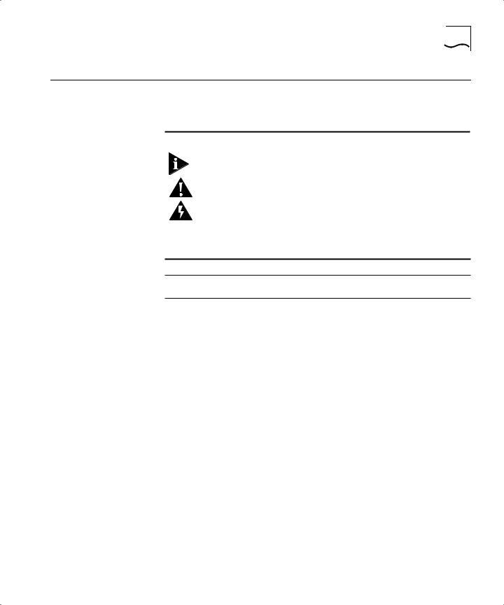
Table 1 Notice Icons |
Icon |
Notice Type |
Alerts you to... |
|
|
|
|
Note |
Important features or instructions |
|
Caution |
Risk of personal injury, system damage, or loss |
|
|
of data |
|
Warning |
Risk of severe personal injury |
|
|
|
Table 2 Text Conventions
Convention Description
Screen displays This typeface represents information as it appears on the screen.
The words “enter” |
When you see the word “enter” in this guide, you must |
and “type” |
type something, and then press the Return or Enter key. Do |
|
not press the Return or Enter key when an instruction |
|
simply says “type.” |
|
|
[Key] names |
Key names appear in text in one of two ways: |
|
■ Referred to by their labels, such as “the Return key” or |
|
“the Escape key” |
|
■ Written with brackets, such as [Return] or [Esc] |
|
If you must press two or more keys simultaneously, the key |
|
names are linked with a plus sign (+). Example: |
|
Press [Ctrl]+[Alt]+[Del]. |
|
|
Words in italicized |
Italics emphasize a point or denote new terms at the place |
type |
where they are defined in the text. |
|
|
Words in boldface |
Bold text denotes key features. |
type |
|
|
|

4 ABOUT THIS GUIDE
Command Syntax You may see a variety of symbols shown as part of the command Symbols syntax. These symbols explain how to enter the command, and you do
not type them as part of the command itself. Table 3 summarizes command syntax symbols.
Table 3 Command Syntax Symbols
Symbol |
Description |
|
|
angle brackets < > |
Enclose a variable or value. You must specify the variable or value. For example, in |
|
the syntax |
|
config vlan <name> ipaddress <ip_address> |
|
you must supply a VLAN name for <name> and an address for <ip_address> when |
|
entering the command. Do not type the angle brackets. |
square brackets [ ] |
Enclose a required value or list of required arguments. One or more values or |
|
arguments can be specified. For example, in the syntax |
|
disable vlan [<name> | all] |
|
you must specify either the VLAN name for <name>, or the keyword “all” when |
|
entering the command. Do not type the square brackets. |
vertical bar | |
Separates mutually exclusive items in a list, one of which must be entered. For |
|
example, in the syntax |
|
config snmp community [read | write] <string> |
|
you must specify either the read or write community string in the command. Do not |
|
type the vertical bar. |
braces { } |
Enclose an optional value or a list of optional arguments. One or more values or |
|
arguments can be specified. For example, in the syntax |
|
show vlan {<name> | all} |
|
you can specify either a particular VLAN or the keyword “all.” If you do not specify |
|
an argument, the command will show all VLANs. Do not type the braces. |
|
|

Line-Editing Commands |
5 |
Line-Editing |
Table 4 describes the line-editing commands available using the |
Commands |
command-line interface. |
Table 4 Line-Editing Commands |
|
|
|
Command |
Description |
|
|
Backspace |
Deletes character to the left of cursor and shifts remainder of line to left. |
Delete or [Ctrl] + D |
Deletes character under cursor and shifts remainder of line to left. |
[Ctrl] + K |
Deletes characters from under cursor to the end of the line. |
Insert |
Toggles on and off. When toggled on, inserts text and pushes previous text to right. |
Left Arrow |
Moves cursor to left. |
Right Arrow |
Moves cursor to right. |
Home or [Ctrl]+A |
Moves cursor to first character in line. |
End or [Ctrl]+E |
Moves cursor to last character in line. |
[Ctrl]+L |
Clears the screen and moves the cursor to the beginning of the line. |
Up Arrow |
Displays the previous command in the command history buffer, and places cursor at |
|
end of command. |
Down Arrow |
Displays the next command in the command history buffer, and places cursor at end |
|
of command. |
|
|
The command syntax is explained in Chapter 4.
Related
Publications
The Switch 3800 documentation set includes the following:
■SuperStack II Switch 3800 Quick Reference Guide. Part Number DQA1691-OAAA01.
■SuperStack II Switch 3800 Quick Installation Guide. Part Number DIA1691-OAAA01.
■SuperStack II Switch 3800 Release Note. Part Number DNA1691-OAAA01.
3Com’s home page can be found at the following web site:
■ http://www.3com.com/

6 ABOUT THIS GUIDE

SWITCH 3800 OVERVIEW
1
|
This chapter describes the following: |
|
|
■ |
Switch 3800 features |
|
■ How to use the Switch 3800 in your network configuration |
|
|
■ Switch 3800 front view |
|
|
■ Switch 3800 rear view |
|
|
■ |
Factory default settings |
|
|
|
About the |
Network managers are currently faced with the challenge of creating |
|
Switch 3800 |
networks that can provide high-speed and high performance to serve |
|
|
the needs of today’s network users. |
|
Part of the 3Com SuperStack® II range of products, the Switch 3800 provides switching and IP Routing between multiple 10BASE-T/100BASE-TX ports and one Gigabit Ethernet port.
Summary of
Features
The Switch 3800 has the following features:
■24 autosensing 10BASE-T/100BASE-TX ports, one Gigabit Ethernet port, and one redundant Gigabit Ethernet port
■Support for 12,000 addresses in the Switch forwarding database
■Fully nonblocking operation
■ All ports transmit and receive packets at wire speed
■Full-duplex operation
■2Mb packet memory

1-2 CHAPTER 1: SWITCH 3800 OVERVIEW
■Virtual LANs (VLANs)
■Support for 64 VLANs on a single Switch 3800
■Support for IEEE 802.1Q tagging
■Controls traffic (including broadcasts)
■Provides extra security
■Protocol-sensitive filtering for VLANs
■Recognition of the Priority Access Control Enabled (PACE) bit set by 3Com Etherlink® adapters and the other devices that support PACE
■Responds to 802.3x flow-control messages
■Autonegotiation to IEEE 802.3z for Gigabit Ethernet
■Load sharing
■Spanning Tree Protocol (IEEE 802.1d)
■Multiple spanning trees (64)
■Wire speed Internet Protocol (IP) via Routing Information Protocol (RIP) version 1 and RIP version 2
■Wire speed Internet Protocol (IP) unicast routing
■3Com’s SuperStack® II architecture
■Integrated network management
■19-inch rack or free-standing mounting
■Agent support
■Simple Network Management Protocol (SNMP)
■Remote Monitoring (RMON) groups 1 to 4 — statistics, history, alarms, and events
■Repeater and Bridge Management Information Base (MIB)
■Easy software upgrades
■BOOTP for automatic Internet Protocol (IP) address configuration
■Local management
Summary of Features 1-3
Port Connections The Switch 3800 has 24 autosensing 10BASE-T/100BASE-TX ports with standard RJ-45 connectors, and supports one Gigabit Ethernet port, and one redundant Gigabit Ethernet port with standard Gigabit Interface Connectors (GBICs). You must have a 3Com-approved GBIC module (such as 3C16911) inserted to make use of these ports. You can connect other Gigabit Ethernet devices (such as 10/100 Switches that have Gigabit Ethernet modules) to the Switch 3800. You can also connect Switch 3800 devices to each other.
10BASE-T/100BASE-TX ports are configured as MDIX (crossover). A crossover cable will typically be needed to connect these ports to another 3Com Switch.
Full-duplex The Switch 3800 provides full-duplex support for all ports. Full-duplex allows frames to be transmitted and received simultaneously and, in effect, doubles the bandwidth available on a link. All 10/100 Mbps ports on the Switch 3800 autonegotiate for halfor full-duplex operation.
Port Redundancy The Switch 3800 has an optional redundant Gigabit Ethernet port to provide resilient links. Using the redundant port (the redundant port is labeled 25-Standby), you can dual-home to one or two Switches. Figure 1-1 illustrates a Switch 3800 dual-homed to two different Switches.
|
Dual-homed |
Standby |
Main |
Figure 1-1 Dual-homing configuration

1-4 CHAPTER 1: SWITCH 3800 OVERVIEW
In the event that the active main port fails or loses link status, the standby port is automatically activated. When the main port resumes operation, the standby port becomes inactive. This feature can be disabled.
Load Sharing Load sharing with Switch 3800 Switches allows the user to increase bandwidth and resilience between Switches by using a group of ports to carry traffic in parallel between Switches. The sharing algorithm allows the Switch to use multiple ports as a single logical port. For example, Virtual LANs (VLANs) see the load-sharing group as a single virtual port. The algorithm also guarantees packet sequencing between clients.
For information on load sharing, refer to Chapter 3.
Switch Operation The Switch 3800 uses the same algorithm as a conventional 802.1d bridge for filtering, forwarding, and learning packets.
Virtual LANs (VLANs)
The Switch 3800 has a Virtual LAN (VLAN) feature that allows you to build your network segments without being restricted by physical connections. A VLAN is a group of locationand topology-independent devices that communicate as if they are on the same physical Local Area Network (LAN). Implementing VLANs on your network has the following three advantages:
■It eases the change and movement of devices on networks. If a device in VLAN marketing is moved to a port in another part of the network, all you must do is specify that the new port belongs to VLAN marketing.
■It helps to control broadcast traffic. If a device in VLAN marketing transmits a broadcast frame, only VLAN marketing devices receive the frame.
■It provides extra security. Devices in VLAN marketing can only communicate with devices on VLAN sales using a device that provides routing services.
For more information on VLANs, refer to Chapter 5.
Network Configuration Example 1-5
Priority Access Control Enabled (PACE)
The Switch recognizes the PACE bit set by 3Com Etherlink® adapters and other devices supporting PACE. When enabled, traffic with these bits receives priority service from the Switch.
Spanning Tree Protocol (STP)
The Switch 3800 supports the IEEE 802.1d Spanning Tree Protocol (STP), which is a bridge-based mechanism for providing fault tolerance on networks. STP allows you to implement parallel paths for network traffic, and ensure the following:
■Redundant paths are disabled when the main paths are operational.
■Redundant paths are enabled if the main traffic paths fail.
For more information on STP, refer to Chapter 7.
IP Unicast Routing
The Switch 3800 can route IP traffic between the VLANs configured as virtual router interfaces. Both dynamic and static IP routes are maintained in the routing table. RIP version 1 and RIP version 2 are supported.
For more information on IP unicast routing, refer to Chapter 8.
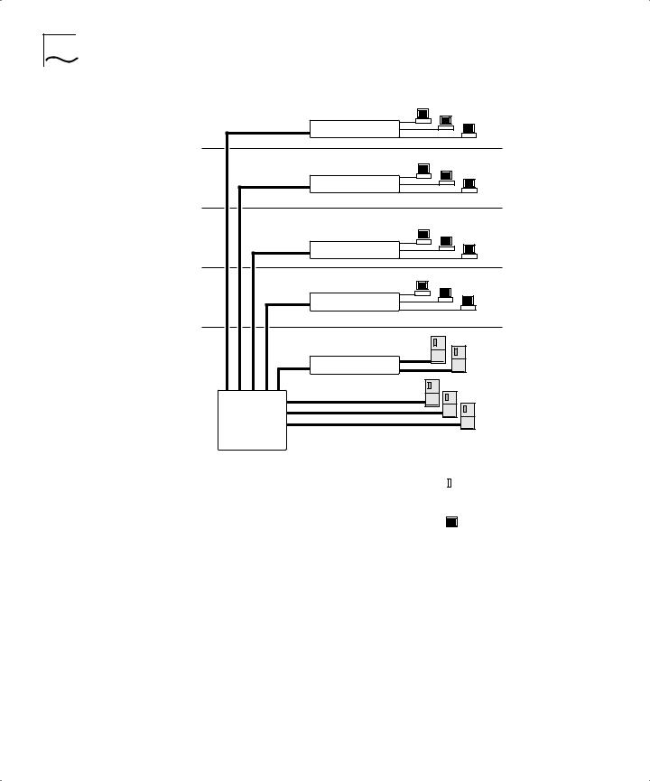
Network |
This section describes where to position the Switch 3800 within your |
Configuration |
network. One common use of the Switch 3800 is on a Gigabit Ethernet |
Example |
backbone. Figure 1-2 shows an example of a Gigabit Ethernet |
|
backbone within a building. |
1-6 CHAPTER 1: SWITCH 3800 OVERVIEW
Switch 1100
Switch 1100
Switch 1100
Switch 1100
Switch 3300
Switch 3800
|
|
|
|
|
|
|
|
To Backbone |
||||
|
Key |
|
|
|
|
|
|
|
||||
|
|
|
|
|
|
|
|
|||||
|
Ethernet |
|
Server |
|
|
|
||||||
|
|
|
|
|
|
|||||||
|
Fast Ethernet |
|
|
|
|
|
|
|||||
|
|
|
|
|
|
|
|
|
||||
|
|
|
|
|
|
|
||||||
|
Gigabit Ethernet |
|
|
Workstation |
|
|
||||||
|
|
|
|
|||||||||
|
|
|
|
|
|
|
|
|
|
|
|
|
Figure 1-2 Switch 3800 used in a backbone configuration
The Switch 1100 on each floor has a 100Mbps full-duplex link to the Switch 3800. A Switch 3300 is connected to a group of servers on one floor of the building. The Switch 3800 routes IP traffic between the IP subnets on each floor, and also provides bridged connectivity for non-IP traffic. The Gigabit Ethernet port on the Switch 3800 connects into a Gigabit Ethernet campus backbone.
Using Gigabit Ethernet as a backbone technology removes bottlenecks by providing scalable bandwidth, low-latency, and high-speed data switching.

Switch 3800 Front View 1-7
In addition to providing a fast backbone between Ethernet LANs, Gigabit Ethernet equipped file servers and services may be directly attached to the Switch 3800 providing improved performance to the Ethernet desktop.
Switch 3800 Front Figure 1-3 shows the Switch 3800 front view.
View
Unit status LEDs
10/100 Mbps ports
1 |
2 |
3 |
4 |
5 |
6 |
7 |
8 |
|
|
9 |
10 |
11 |
12 |
13 |
14 |
15 |
16 |
25 |
25 |
17 |
18 |
19 |
20 |
21 |
22 |
23 |
24 |
25 |
25 |
10/100 Mbps ports |
|
Port status LEDs Gigabit Ethernet ports |
|
Figure 1-3 Switch 3800 front view
The front panel has the following features:
Ports
The Switch 3800 has 24 autosensing 10BASE-T/100BASE-TX ports using standard RJ-45 connectors, and supports one Gigabit Ethernet port, and one redundant Gigabit Ethernet port using standard Gigabit Interface Connectors (GBICs). You must have a GBIC transceiver module inserted to make use of these ports.
The Switch 3800 ports support the media types and distances listed in
Table 1-1.

1-8 CHAPTER 1: SWITCH 3800 OVERVIEW
Table 1-1 Media Types and Distances
Standard |
Media Type |
Mhz/Km Rating |
Maximum Distance |
|
|
|
|
10BASE-T |
Category 3 UTP Cable (10Mbps) |
|
100 Meters |
100BASE-TX |
Category 5 UTP Cable (100Mbps) |
|
100 Meters |
1000BASE-SX |
62.5/125 um Multimode fiber |
160 |
220 Meters |
(850 nm) |
62.5/125 um Multimode fiber |
200 |
275 Meters |
|
50/125 um Multimode fiber |
400 |
500 Meters |
|
50/125 um Multimode fiber |
500 |
550 Meters |
1000BASE-LX |
62.5/125 um Multimode fiber |
500 |
550 Meters |
(1300 nm) |
50/125 um Multimode fiber |
400 |
550 Meters |
|
50/125 um Multimode |
500 |
550 Meters |
|
10u Single-mode fiber |
NA |
5,000 Meters |
|
|
|
|
For more information on 1000BASE-SX and 1000BASE-LX characteristics refer to IEEE Draft P802.3z/D4.2 Tables 38-2 and 38-6.
LEDs
Table 1-2 describes the LED behavior on the Switch 3800.
Table 1-2 |
Switch 3800 LEDs |
|
|
|
|
LED |
Color |
Indicates |
|
|
|
10/100Mbps Port Status LEDs |
|
|
|
Green |
Link is present; port is enabled. |
|
Yellow |
Frames are being transmitted/received on this |
|
|
port. |
|
Green flashing |
Link is present; port is disabled. |
|
Off |
Link is not present. |
Gigabit Ethernet Port Status LEDs |
|
|
Packet |
Yellow |
Frames are being transmitted/received on this |
|
|
port. |
|
Off |
No activity on this port. |
Status |
Green |
Link is present; port is enabled; full-duplex |
|
|
operation. |
|
Green flashing |
Link is present; port is disabled. |
|
Off |
Link is not present. |
(continued)
Switch 3800 Rear View 1-9
Table 1-2 Switch 3800 LEDs (continued)
LED |
Color |
Indicates |
|
|
|
Unit Status LEDs |
|
|
Power |
Green |
The Switch 3800 is powered up. |
|
Yellow |
The Switch 3800 is indicating a power, |
|
|
overheat, or fan failure. |
MGMT |
Green |
The Switch 3800 is operating normally. |
|
Green flashing |
Software download is in progress. |
|
|
Power On Self Test (POST) is in progress. |
|
Yellow |
The Switch 3800 has failed its POST, or is |
|
|
indicating an overheat condition. |
|
|
|
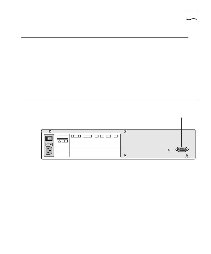
Switch 3800 Rear Figure 1-4 shows the Switch 3800 rear view.
View
Power socket and fuse |
Console port |
! |
U C U
L L
MADE IN USA |
3C16990 |
MAIN ASSEMBLY
SERIAL NUMBER
MAC ADDRESS
Figure 1-4 Switch 3800 rear view
The rear panel has the following features:
Power Socket
The Switch 3800 automatically adjusts to the supply voltage. The power supply operates down to 90 V. The fuse is suitable for both 110 V AC and 220-240 V AC operation.
Serial Number
The serial number uniquely identifies this unit. You may need this serial number for fault-reporting purposes.

1-10 CHAPTER 1: SWITCH 3800 OVERVIEW
MAC Address
This label shows the unique Ethernet MAC address assigned to this device.
Console Port
The console port (9-pin, “D” type connector) is used to connect a terminal and to carry out local out-of-band management.
Factory Defaults Table 1-3 shows the factory defaults for the Switch 3800 features.
Table 1-3 Switch 3800 Factory Defaults
Item |
Default Setting |
|
|
Port status |
Enabled on all ports |
Default user account |
admin with no password and user with no |
|
password |
Console port configuration |
9600 baud, eight data bits, one stop bit, no |
|
parity, XON/XOFF flow control enabled |
SNMP read community string |
Public |
SNMP write community string |
Private |
RMON history session |
Enabled |
RMON alarms |
Enabled |
|
■ Send trap if load is greater than 75% of |
|
available bandwidth |
|
■ Send trap if there are more than 10 errors in |
|
1,000 packets |
PACE |
Recognition disabled |
Virtual LANs |
One VLAN named default; all ports belong to the |
|
default VLAN; no protocol filter used. |
802.1Q tagging |
All packets are untagged on the default VLAN |
|
(default) |
BOOTP |
Enabled on the default VLAN (default) |
Spanning Tree Protocol |
Disabled; one defined as “s0” |
IP Routing |
Disabled |
Forwarding database aging |
30 minutes |
period |
|
RIP Protocol |
Disabled |
Autonegotiation |
On |
|
|

INSTALLATION AND SETUP
2
|
This chapter describes the following: |
|
■ How to decide where to install the Switch 3800 |
|
■ Ethernet configuration rules |
|
■ How to install the Switch in a rack or free-standing |
|
■ How to connect equipment to the console port |
|
■ How to check the installation using the Power On Self-Test (POST) |
|
|
Following Safety |
Before installing or removing any components of the Switch, or before |
Information |
carrying out any maintenance procedures, you must read the safety |
|
information provided in Appendix A of this guide. |
|
|
Determining the |
The Switch 3800 is suited for use in the office, where it can be |
Switch 3800 |
free-standing or mounted in a standard 19-inch equipment rack. |
Location |
Alternatively, the device can be rack-mounted in a wiring closet or |
|
equipment room. Two mounting brackets are supplied with the Switch. |
|
CAUTION: When using a rack mounting system, the Switch must be |
|
mounted on a shelf or runners. The rack mounting brackets alone are |
|
not sufficient to support the weight of the Switch. The rack mounting |
|
brackets are provided to ensure stability across the horizontal plane. If |
|
you stack Switches, you must ensure that the shelf or runners are |
|
strong enough to hold the combined weight. Ensure that the |
|
ventilation holes are not obstructed. |
After deciding where to install the Switch, make sure that:
■You will be able to meet the configuration rules detailed in Chapter 1.
■The Switch is accessible and cables can be connected easily.

2-2 CHAPTER 2: INSTALLATION AND SETUP
■Water or moisture cannot enter the case of the unit.
■Temperature must be within the range of 0 to 40 degrees Celsius.
■Air-flow around the unit and through the vents in the side of the case is not restricted. You should provide a minimum of 25mm (1-inch) clearance.
■No objects are placed on top of the unit.
■Units are not stacked more than four high if the Switch is free-standing.
Configuration Rules The connectors, supported media types, and maximum distances for for Ethernet the Switch 3800 are described in Chapter 1.
Installing the |
The Switch 3800 can be mounted in a rack, or placed free-standing on |
Switch 3800 |
a tabletop. |
Rack Mounting |
The Switch 3800 is 2U high and will fit in most standard 19-inch racks. |
|
CAUTION: The Switch should only be used in a rack if it is mounted on |
|
runners, a shelf, or a tray to support the weight. The rack mount kits |
|
alone are not sufficient to support the weight of the Switch. The rack |
|
mount kits must not be used to suspend the Switch from under a table |
|
or desk, or attach it to a wall. |
|
To install the mounting brackets on the Switch, follow these steps: |
1Place the Switch the right way up on a hard flat surface, with the front facing toward you.
2Remove the existing screws from the sides of the chassis.
3Locate a mounting bracket over the mounting holes on one side of the unit.
4Insert the four screws and fully tighten with a suitable screwdriver, as shown in Figure 2-1.
 Loading...