


 Loading...
3Com Baseline Switch 2900 Family
Getting Started Guide
Manual Version: 5W100
www.3com.com
3Com Corporation
350 Campus Drive, Marlborough,
MA, USA 01752 3064
Copyright © 2009, 3Com Corporation. All rights reserved. No part of this documentation may be reproduced in any form or by any means or used to make any derivative work (such as translation, transformation, or adaptation) without written permission from 3Com Corporation.
3Com Corporation reserves the right to revise this documentation and to make changes in content from time to time without obligation on the part of 3Com Corporation to provide notification of such revision or change.
3Com Corporation provides this documentation without warranty, term, or condition of any kind, either implied or expressed, including, but not limited to, the implied warranties, terms or conditions of merchantability, satisfactory quality, and fitness for a particular purpose. 3Com may make improvements or changes in the product(s) and/or the program(s) described in this documentation at any time.
If there is any software on removable media described in this documentation, it is furnished under a license agreement included with the product as a separate document, in the hard copy documentation, or on the removable media in a directory file named LICENSE.TXT or !LICENSE.TXT. If you are unable to locate a copy, please contact 3Com and a copy will be provided to you.
UNITED STATES GOVERNMENT LEGEND
If you are a United States government agency, then this documentation and the software described herein are provided to you subject to the following:
All technical data and computer software are commercial in nature and developed solely at private expense. Software is delivered as “Commercial Computer Software” as defined in DFARS 252.227-7014 (June 1995) or as a “commercial item” as defined in FAR 2.101(a) and as such is provided with only such rights as are provided in 3Com’s standard commercial license for the Software. Technical data is provided with limited rights only as provided in DFAR 252.227-7015 (Nov 1995) or FAR 52.227-14 (June 1987), whichever is applicable. You agree not to remove or deface any portion of any legend provided on any licensed program or documentation contained in, or delivered to you in conjunction with, this User Guide.
Unless otherwise indicated, 3Com registered trademarks are registered in the United States and may or may not be registered in other countries.
3Com and the 3Com logo are registered trademarks of 3Com Corporation.
All other company and product names may be trademarks of the respective companies with which they are associated.
ENVIRONMENTAL STATEMENT
It is the policy of 3Com Corporation to be environmentally-friendly in all operations. To uphold our policy, we are committed to:
Establishing environmental performance standards that comply with national legislation and regulations. Conserving energy, materials and natural resources in all operations.
Reducing the waste generated by all operations. Ensuring that all waste conforms to recognized environmental standards. Maximizing the recyclable and reusable content of all products.
Ensuring that all products can be recycled, reused and disposed of safely.
Ensuring that all products are labelled according to recognized environmental standards. Improving our environmental record on a continual basis.
End of Life Statement
3Com processes allow for the recovery, reclamation and safe disposal of all end-of-life electronic components.
Regulated Materials Statement
3Com products do not contain any hazardous or ozone-depleting material.
Environmental Statement about the Documentation
The documentation for this product is printed on paper that comes from sustainable, managed forests; it is fully biodegradable and recyclable, and is completely chlorine-free. The varnish is environmentally-friendly, and the inks are vegetable-based with a low heavy-metal content.

About This Manual
Organization
3Com Baseline Switch 2900 Family Getting Started Guide is organized as follows:
|
Chapter |
Contents |
|
|
|
Briefly introduces the appearance, system description, as |
|
1 |
Product Overview |
well as the features and applications of the 3Com Baseline |
|
|
|
Switch 2900 Family. |
|
|
|
|
|
|
|
Describes the requirements on installation site, the safety |
|
2 |
Installation Preparations |
recommendations before and during installation, and the |
|
|
|
required tools. |
|
|
|
|
|
|
|
Covers the procedures for installing the 3Com Baseline |
|
3 |
Installing a Switch |
Switch 2900 Family, ground wire connection, power |
|
module installation, interface module installation, and so |
|||
|
|
||
|
|
on. |
|
|
|
|
|
|
|
Helps you get familiar with the basic knowledge of how to |
|
4 |
Initial Power-On |
boot and configure the 3Com Baseline Switch 2900 Family, |
|
including device startup, power-on, and initialization of |
|||
|
|
||
|
|
system files, and so on. |
|
|
|
|
|
5 |
Loading Software |
Introduces how to load Boot ROM and host software for the |
|
3Com Baseline Switch 2900 Family |
|||
|
|
||
|
|
|
|
|
|
Introduces the problems that might occur during the |
|
6 |
Maintenance and Troubleshooting |
installation and the booting of the 3Com Baseline Switch |
|
|
|
2900 Family and the related solution. |
|
|
|
|
Conventions
The manual uses the following conventions:
GUI conventions
Convention |
Description |
|
Boldface |
Window names, button names, field names, and menu items are in |
|
Boldface. For example, the New User window appears; click OK. |
||
|
||
|
|
|
> |
Multi-level menus are separated by angle brackets. For example, File > |
|
Create > Folder. |
||
|
||
|
|
Symbols
Convention |
Description |
|
|
Means reader be extremely careful. Improper operation may cause bodily injury.
Means reader be careful. Improper operation may cause data loss or damage to equipment.
Means an action or information that needs special attention to ensure successful configuration or good performance.

Convention |
Description |
|
|
Means a complementary description.
Means techniques helpful for you to make configuration with ease.
Related Documentation
In addition to this manual, each 3Com Baseline Switch 2900 documentation set includes the following:
Manual |
Description |
|
|
Describe how to configure your 3Com Baseline 3Com Baseline Switch 2900 Family User Guide Switch 2900 Family using the supported
protocols
Obtaining Documentation
You can access the most up-to-date 3Com product documentation on the World Wide Web at this URL: http://www.3com.com.
Table of Contents
1Product Overview ······································································································································1-1
Introduction ·············································································································································1-1 3Com Baseline Switch 2920-SFP Plus···································································································1-3 Front Panel ······································································································································1-3 Rear Panel·······································································································································1-3 Power Supply System ·····················································································································1-3 Cooling System ·······························································································································1-3 3Com Baseline Switch 2928-SFP Plus···································································································1-4 Front Panel ······································································································································1-4 Rear Panel·······································································································································1-4 Power Supply System ·····················································································································1-4 Cooling System ·······························································································································1-4 3Com Baseline Switch 2952-SFP Plus···································································································1-5 Front Panel ······································································································································1-5 Rear Panel·······································································································································1-5 Power Supply System ·····················································································································1-5 Cooling System ·······························································································································1-5 3Com Baseline Switch 2928-PWR Plus ·································································································1-6 Front Panel ······································································································································1-6 Rear Panel·······································································································································1-6 Power Supply System ·····················································································································1-6 Cooling System ·······························································································································1-6 3Com Baseline Switch 2928-HPWR Plus·······························································································1-7 Front Panel ······································································································································1-7 Rear Panel·······································································································································1-7 Power Supply System ·····················································································································1-7 Cooling System ·······························································································································1-8 Ports························································································································································1-8 Console Port····································································································································1-8 10/100/1000Base-T Ethernet Port···································································································1-8 1000Base-X SFP Interface··············································································································1-9 LEDs······················································································································································1-10 Power LED ····································································································································1-10 RPS Status LED····························································································································1-10 Port Mode LED······························································································································1-11 10/100/1000Base-T Auto-Sensing Ethernet Port Status LED·······················································1-11 1000Base-X SFP Interface Status LED ························································································1-13
2Installation Preparations···························································································································2-1
Safety Precautions··································································································································2-1 Installation Site········································································································································2-1 Temperature/Humidity·····················································································································2-1 Cleanness········································································································································2-1 Electromagnetic Susceptibility·········································································································2-2
i
Laser Safety ····································································································································2-2 Installation Tools ·····································································································································2-3
3Installing a Switch ·····································································································································3-1
Installing the Switch into a 19-Inch Rack Using Mounting Brackets·······················································3-1 Introduction to Mounting Brackets···································································································3-1 Attaching the Mounting Brackets to a Switch··················································································3-2 Mounting the Switch to a Rack········································································································3-4 Mounting the Switch on a Workbench ····································································································3-6 Connecting the PGND Cable ··················································································································3-6 When a Grounding Strip is Available·······························································································3-6 Where a Grounding Conductor Can be Buried ···············································································3-8 In Other Installation Sites ················································································································3-8
Connecting the Power Cord····················································································································3-9 Connecting an AC Power Cord ·······································································································3-9 Connecting an RPS DC Power Cord·····························································································3-10 Verifying the Installation························································································································3-10
4Initial Power-On ·········································································································································4-1
Setting Up the Configuration Environment······························································································4-1 Connecting the Console Cable ···············································································································4-1 Console Cable ·································································································································4-1 Connection Procedure·····················································································································4-2 Setting Terminal Parameters ··················································································································4-2 Booting the Switch ··································································································································4-5 Checking Before Power-On·············································································································4-5 Powering On the Switch ··················································································································4-5 Changing the Boot Mode·················································································································4-7
5Loading Software·······································································································································5-1
Introduction ·············································································································································5-1 Approaches for Loading Application and Configuration Files·································································5-1 Loading Files Through the Boot ROM Menu ··························································································5-1 Introduction to the Boot ROM Menu································································································5-2 Loading Files Using XMODEM Through Console Port ···································································5-3 Loading Files Using TFTP Through Ethernet Port ········································································5-11 Loading Files Using FTP Through Ethernet Port ··········································································5-14
6Maintenance and Troubleshooting··········································································································6-1
File Loading Failure·································································································································6-1 Password Loss········································································································································6-1 User Password Loss························································································································6-1 Boot ROM Password Loss ··············································································································6-1 Power Supply Failure······························································································································6-2 Configuration Terminal Failure················································································································6-3
ii

1 Product Overview
Introduction
The 3Com Baseline Switch 2900 Family are Layer 2 Gigabit Ethernet switches developed by 3Com. They are intelligent manageable switches designed for network environments where high performance, high-density port distribution, and easy installation are required.
With 10/100/1000 Mbps Ethernet interfaces, the 3Com Baseline Switch 2900 Family are mainly deployed at the access layer in enterprise networks requiring Gigabit to the Desktop (GTTD) application and at the distribution layer in metropolitan-area networks (MANs). In the latter deployment, the 3Com Baseline Switch 2900 Family provide GE electrical interfaces for user access or low-end switch convergence in the downlink direction. Whereas, in the uplink direction, they are aggregated to large-capacity Layer 3 switches or switches at the exchange office through their GE interfaces.
Table 1-1 shows the models and system specifications of the 3Com Baseline Switch 2900 Family.
Table 1-1 The 3Com Baseline Switch 2900 Family system specifications
|
|
|
|
|
|
|
|
Description |
|
|
|
|
|
|
|
|
|
3Com |
|
3Com |
|
3Com |
|
3Com |
|
3Com |
|
|
|
Item |
|
Baseline |
|
Baseline |
|
Baseline |
|
Baseline |
|
Baseline |
|
|
|
|
|
Switch |
|
Switch |
|
Switch |
|
Switch |
|
Switch |
|
|
|
|
|
2920-SFP |
|
2928-SFP |
|
2952-SFP |
|
2928-PWR |
|
2928-HPWR |
|
|
|
|
|
Plus |
|
Plus |
|
Plus |
|
Plus |
|
Plus |
|
|
|
Physical |
43.6 × 440 × |
|
43.6 × 440 × |
|
43.6 × 440 × |
|
43.6 × 440 × |
43.6 × 440 × |
|
||
|
|
dimension |
|
160 mm (1.72 |
160 mm (1.72 |
260 mm (1.72 |
420 mm (1.72 |
|
420 mm (1.72 |
||||
|
|
s (H × W × |
× 17.32 × 6.30 |
|
× 17.32 × 6.30 |
|
× 17.32 × |
|
× 17.32 × |
× 17.32 × |
|
||
|
|
D) |
|
in.) |
in.) |
10.24 in.) |
16.54 in.) |
|
16.54 in.) |
||||
|
|
|
|
|
|
|
|
|
|
||||
|
|
Weight |
|
ñ 3 kg (6.61 lb) |
ñ 3 kg (6.61 lb) |
ñ 5 kg (11.02 |
ñ 7 kg (15.43 |
|
ñ 7 kg (15.43 |
||||
|
|
|
|
|
|
|
|
lb) |
lb) |
|
lb) |
||
|
|
Console |
1 |
|
1 |
|
1 |
|
1 |
1 |
|
||
|
|
port |
|
|
|
|
|||||||
|
|
|
|
|
|
|
|
|
|
|
|
|
|
|
|
|
|
|
|
|
|
|
|
|
|
||
|
|
|
16 × |
|
24 × |
|
48 × |
|
24 × |
24 × |
|
||
|
|
|
|
10/100/1000B |
10/100/1000B |
10/100/1000B |
10/100/1000Ba |
|
10/100/1000B |
||||
|
|
Service |
|
ase-T |
ase-T |
ase-T |
se-T |
|
ase-T |
||||
|
|
|
autosensing |
autosensing |
autosensing |
autosensing |
|
autosensing |
|||||
|
|
ports |
|
|
|||||||||
|
|
|
Ethernet ports |
Ethernet ports |
Ethernet ports |
Ethernet ports |
|
Ethernet ports |
|||||
|
|
|
|
|
|||||||||
|
|
|
|
+ 4 GE SFP |
+ 4 GE SFP |
+ 4 GE SFP |
+ 4 GE SFP |
|
+ 4 GE SFP |
||||
|
|
|
|
interfaces |
interfaces |
interfaces |
interfaces |
|
interfaces |
||||
|
|
|
|
|
|
|
|
|
|
|
|
|
|
1-1

|
|
|
|
|
|
|
|
|
Description |
|
|
|
|
|
|
|
|
3Com |
|
3Com |
|
3Com |
3Com |
|
3Com |
|
|
Item |
|
Baseline |
|
Baseline |
|
Baseline |
Baseline |
|
Baseline |
|
|
|
|
|
|
Switch |
|
Switch |
|
Switch |
Switch |
|
Switch |
|
|
|
|
|
2920-SFP |
|
2928-SFP |
|
2952-SFP |
2928-PWR |
|
2928-HPWR |
|
|
|
|
|
Plus |
|
Plus |
|
Plus |
Plus |
|
Plus |
|
|
|
AC |
|
Rated voltage range: 100 VAC to 240 VAC, 50 Hz or 60 Hz |
|
|
|||||
|
|
|
|
Maximum voltage range: 90 VAC to 264 VAC, 47 Hz or 63 Hz |
|
|
||||||
|
|
|
|
|
|
|
||||||
|
|
|
|
|
|
|
|
|
|
|
|
|
|
|
Inp |
|
|
|
|
|
|
|
|
|
Use the |
|
|
|
|
|
|
|
|
|
|
|
external RPS |
|
|
|
ut |
|
|
|
|
|
|
|
|
|
|
|
|
|
|
|
|
|
|
|
|
|
unit provided |
|
|
|
volt |
RP |
|
|
|
|
|
|
|
|
|
|
|
|
|
|
|
|
|
|
|
by 3Com only, |
||
|
|
ag |
|
|
|
|
|
|
|
|
||
|
|
S |
|
— |
|
|
|
|
|
|
with the rated |
|
|
|
e |
|
|
|
|
|
|
|
|||
|
|
DC |
|
|
|
|
|
|
|
|
voltage |
|
|
|
|
|
|
|
|
|
|
|
|
||
|
|
|
|
|
|
|
|
|
|
|
|
ranging from |
|
|
|
|
|
|
|
|
|
|
|
|
–52 VDC to |
|
|
|
|
|
|
|
|
|
|
|
|
–55 VDC |
|
|
|
|
|
|
|
|
|
|
|
|
|
|
|
Supported |
|
— |
|
|
|
|
|
|
RPS1000-A3 |
|
|
|
RPS unit |
|
|
|
|
|
|
|
|||
|
|
|
|
|
|
|
|
|
|
|
||
|
|
|
|
|
|
|
|
|
|
|
|
|
|
|
Power |
|
|
|
|
|
|
|
|
AC: 45.6W |
|
|
|
consumpti |
|
11.9W |
|
13.4W |
|
25.7W |
25.0W |
|
||
|
|
|
|
|
|
DC: 27.5W |
||||||
|
|
on |
|
|
|
|
|
|
|
|
|
|
|
|
|
|
|
|
|
|
|
|
|
|
|
|
|
|
|
|
|
|
|
|
|
|
|
|
|
|
|
|
|
|
|
|
|
|
|
|
AC power |
|
|
|
|
|
|
|
|
|
|
|
|
input: 523 W |
|
|
|
|
|
|
|
|
|
|
|
|
(158 W for |
|
|
|
|
|
|
|
|
|
|
|
|
system power |
|
|
|
|
|
|
|
|
|
|
255 W (85 W |
|
consumption |
|
|
Power |
|
|
|
|
|
|
|
and 365 W for |
||
|
|
|
|
|
|
|
|
for system |
|
|||
|
|
|
|
|
|
|
|
|
PoE power |
|||
|
|
consumpti |
|
|
|
|
|
|
power |
|
||
|
|
|
|
|
|
|
|
|
consumption) |
|||
|
|
on (full |
|
22.4 W |
|
31.5 W |
|
55.4 W |
consumption |
|
||
|
|
|
|
|
|
DC power |
||||||
|
|
configurati |
|
|
|
|
|
|
and 170 W for |
|
||
|
|
|
|
|
|
|
|
|
input: 832 W |
|||
|
|
on) |
|
|
|
|
|
|
|
PoE power |
|
|
|
|
|
|
|
|
|
|
|
|
(92 W for |
||
|
|
|
|
|
|
|
|
|
|
consumption) |
|
|
|
|
|
|
|
|
|
|
|
|
|
system power |
|
|
|
|
|
|
|
|
|
|
|
|
|
|
|
|
|
|
|
|
|
|
|
|
|
|
consumption |
|
|
|
|
|
|
|
|
|
|
|
|
and 740 W for |
|
|
|
|
|
|
|
|
|
|
|
|
PoE power |
|
|
|
|
|
|
|
|
|
|
|
|
consumption) |
|
|
|
|
|
|
|
|
|
|
|
|
|
|
|
Operating |
|
|
|
|
|
|
|
|
|
|
|
|
temperatu |
|
0°C to 45°C (32°F to 113°F) |
|
|
|
|
|
|||
|
|
re |
|
|
|
|
|
|
|
|
|
|
|
|
|
|
|
|
|
|
|
|
|
|
|
|
|
Operating |
|
|
|
|
|
|
|
|
|
|
|
|
humidity |
|
10% to 90% |
|
|
|
|
|
|
|
|
|
|
(nonconde |
|
|
|
|
|
|
|
|
||
|
|
|
|
|
|
|
|
|
|
|
||
|
|
nsing) |
|
|
|
|
|
|
|
|
|
|
|
|
|
|
|
|
|
|
|
|
|
|
|
1-2
3Com Baseline Switch 2920-SFP Plus
Front Panel
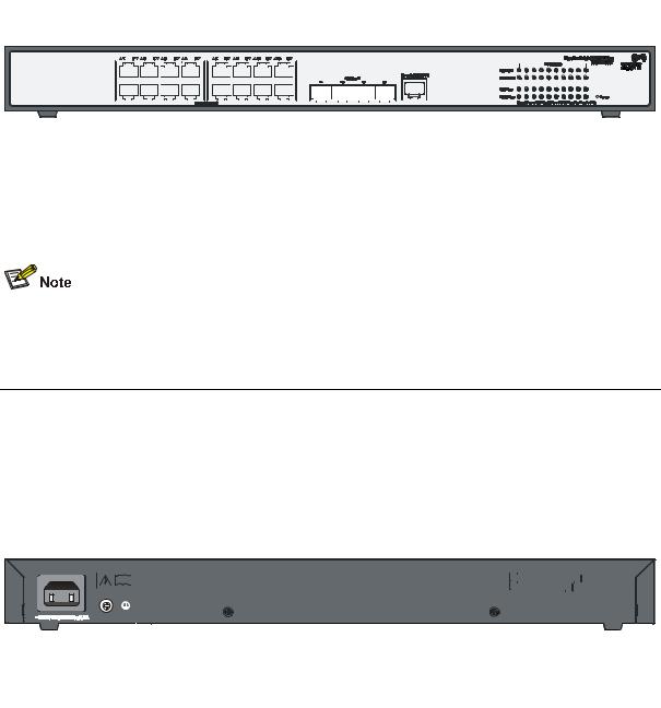
Figure 1-1 3Com Baseline Switch 2920-SFP Plus front panel
|
|
|
|
|
|
|
|
|
|
|
|
|
|
|
|
|
|
|
|
|
|
|
|
|
|
|
|
|
|
|
|
|
|
|
|
|
|
|
|
|
|
|
|
|
|
|
|
|
|
|
|
|
|
|
|
|
|
|
|
|
|
|
|
|
|
|
|
|
|
|
|
|
|
|
|
|
|
|
|
|
|
|
|
|
|
|
|
|
|
|
|
|
|
|
|
|
|
|
|
|
|
|
|
|
|
|
|
|
|
|
|
|
|
|
|
|
|
|
|
|
|
|
|
|
|
|
|
|
|
|
|
|
|
|
|
|
|
|
|
|
|
|
|
|
|
|
|
|
|
|
|
|
|
|
|
|
|
|
|
|
|
|
|
|
|
|
|
|
|
|
|
|
|
|
|
|
|
|
|
|
|
|
|
|
|
|
|
|
|
|
|
|
|
|
|
|
|
|
|
|
|
|
|
|
|
|
|
|
|
|
|
|
|
|
|
|
|
|
|
|
|
|
|
|
|
|
|
|
|
|
|
|
|
|
|
|
|
|
|
|
|
|
|
|
|
|
|
|
|
|
|
|
|
|
|
|
|
|
|
|
|
|
|
|
|
|
|
|
|
|
|
|
|
|
|
|
|
|
|
|
|
|
|
|
|
|
|
|
|
|
|
|
|
|
|
|
|
|
|
|
|
|
|
|
|
|
|
|
|
|
|
|
|
|
|
|
|
|
|
|
|
|
|
|
|
|
|
|
|
|
|
|
|
|
|
|
|
|
|
|
|
|
|
|
|
|
|
|
|
|
|
|
|
|
|
|
|
|
|
|
|
|
|
|
|
|
|
|
|
|
|
|
|
|
|
|
|
|
|
|
|
|
|
|
(1) |
10/100/1000Base-T auto-sensing Ethernet port |
|
(2) |
Port status LED |
|
|||||||||||||||||||||||||||||||||||||||||
|
(3) |
Power LED (Power) |
|
|
|
|
|
|
(4) |
Console port |
|
||||||||||||||||||||||||||||||||||||
|
(5) |
1000Base-X SFP interface |
|
|
|
|
|
|
|
|
|
|
|
|
|
|
|
|
|
|
|
|
|
|
|
|
|
|
|
||||||||||||||||||
|
|
|
|
|
|
|
|
|
|
|
|
|
|
|
|
|
|
|
|
|
|
|
|
|
|
|
|
|
|
|
|
|
|
|
|
|
|
|
|
|
|
|
|
|
|
|
|
10/100/1000Base-T autosensing Ethernet ports on the 3Com Baseline Switch 2900 Family are numbered in up-down and left-right order, with the first upper left one being Port 1, the first lower left one being Port 2, the second upper left one being Port 3, and so on.
Rear Panel
Figure 1-2 3Com Baseline Switch 2920-SFP Plus rear panel
|
|
|
|
|
|
|
|
|
|
|
|
|
|
|
|
|
|
|
|
|
|
|
|
|
|
|
|
|
|
|
|
|
|
|
|
|
|
|
|
|
|
|
|
|
|
|
|
|
|
|
|
|
|
|
|
|
|
|
|
|
|
|
|
|
|
|
|
|
|
|
|
|
|
|
|
|
|
|
|
|
|
|
|
|
|
|
|
|
|
|
|
|
|
|
|
|
|
|
|
|
|
|
|
|
|
|
|
|
|
|
|
|
|
|
|
|
|
|
|
|
|
|
|
|
|
|
|
|
|
|
|
|
|
|
|
|
|
|
|
|
|
|
|
|
|
|
|
|
|
|
|
|
|
|
|
|
|
|
|
|
|
|
|
|
|
|
|
|
|
|
|
|
|
|
|
|
|
|
|
|
|
|
|
|
|
|
|
|
|
|
|
|
|
|
|
|
|
|
|
|
|
|
|
|
|
|
|
|
|
|
|
|
|
|
|
|
|
|
|
|
|
|
|
|
|
|
|
|
|
|
|
|
|
|
|
|
|
|
|
|
|
|
|
|
|
|
|
|
|
|
|
|
|
|
|
|
|
|
|
|
|
|
|
|
|
|
|
|
|
|
|
|
|
|
|
(1) AC receptacle |
|
(2) Grounding screw |
|||||||||||||||||||||
Power Supply System
AC power input:
Rated voltage range: 100 VAC to 240 VAC, 50 Hz or 60 Hz
Input voltage range: 90 VAC to 264 VAC, 47 Hz or 63 Hz
Cooling System
The 3Com Baseline Switch 2920-SFP Plus is equipped with one fan for heat dissipation
1-3
3Com Baseline Switch 2928-SFP Plus
Front Panel
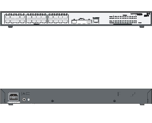
Figure 1-3 3Com Baseline Switch 2928-SFP Plus front panel
|
|
|
|
|
|
|
|
|
|
|
|
|
|
|
|
|
|
|
|
|
|
|
|
|
|
|
|
|
|
|
|
|
|
|
|
|
|
|
|
|
|
|
|
|
|
|
|
|
|
|
|
|
|
|
|
|
|
|
|
|
|
|
|
|
|
|
|
|
|
|
|
|
|
|
|
|
|
|
|
|
|
|
|
|
|
|
|
|
|
|
|
|
|
|
|
|
|
|
|
|
|
|
|
|
|
|
|
|
|
|
|
|
|
|
|
|
|
|
|
|
|
|
|
|
|
|
|
|
|
|
|
|
|
|
|
|
|
|
|
|
|
|
|
|
|
|
|
|
|
|
|
|
|
|
|
|
|
|
|
|
|
|
|
|
|
|
|
|
|
|
|
|
|
|
|
|
|
|
|
|
|
|
|
|
|
|
|
|
|
|
|
|
|
|
|
|
|
|
|
|
|
|
|
|
|
|
|
|
|
|
|
|
|
|
|
|
|
|
|
|
|
|
|
|
|
|
|
|
|
|
|
|
|
|
|
|
|
|
|
|
|
|
|
|
|
|
|
|
|
|
|
|
|
|
|
|
|
|
|
|
|
|
|
|
|
|
|
|
|
|
|
|
|
|
|
|
|
|
|
|
|
|
|
|
|
|
|
|
|
|
|
|
|
|
|
|
|
|
|
|
|
|
|
|
|
|
|
|
|
|
|
|
|
|
|
|
|
|
|
|
|
|
|
|
|
|
|
|
|
|
|
|
|
|
|
|
|
|
|
|
|
|
|
|
|
|
|
|
|
|
|
|
|
|
|
|
|
|
|
|
|
|
|
|
|
|
|
|
|
|
|
|
|
|
|
|
|
|
|
|
|
|
|
|
|
|
|
|
|
|
|
|
|
|
|
|
|
|
|
|
|
|
|
|
|
|
|
|
|
|
|
|
|
|
|
|
|
|
|
|
|
|
|
|
|
|
|
|
|
|
|
(1) |
10/100/1000Base-T auto-sensing Ethernet port |
|
(2) |
|
Port status LED |
|
|
|
|
|
|
||||||||||||||||||||||||||||||||||||||||||
(3) |
Power LED (Power) |
|
|
|
|
(4) |
|
Console port |
|
|
|
|
|
|
|||||||||||||||||||||||||||||||||||||||
(5) |
1000Base-X SFP interface |
|
|
|
|
|
|
|
|
|
|
|
|
|
|
|
|
|
|
|
|
||||||||||||||||||||||||||||||||
Rear Panel
Figure 1-4 3Com Baseline Switch 2928-SFP Plus rear panel
|
|
|
|
|
|
|
|
|
|
|
|
|
|
|
|
|
|
|
|
|
|
|
|
|
|
|
|
|
|
|
|
|
|
|
|
|
|
|
|
|
|
|
|
|
|
|
|
|
|
|
|
|
|
|
|
|
|
|
|
|
|
|
|
|
|
|
|
|
|
|
|
|
|
|
|
|
|
|
|
|
|
|
|
|
|
|
|
|
|
|
|
|
|
|
|
|
|
|
|
|
|
|
|
|
|
|
|
|
|
|
|
|
|
|
|
|
|
|
|
|
|
|
|
|
|
|
|
|
|
|
|
|
|
|
|
|
|
|
|
|
|
|
|
|
|
|
|
|
|
|
|
|
|
|
|
|
|
|
|
|
|
|
|
|
|
|
|
|
|
|
|
|
|
|
|
|
|
|
|
|
|
|
|
|
|
|
|
|
|
|
|
|
|
|
|
|
|
|
|
|
|
|
|
|
|
|
|
|
|
|
|
|
|
|
|
|
|
|
|
|
|
|
|
|
|
|
|
|
|
|
|
|
|
|
|
|
|
|
|
|
|
|
|
|
|
|
|
|
|
|
|
|
|
|
|
|
|
|
|
|
|
|
|
|
|
|
|
|
|
|
|
|
|
|
|
|
|
|
|
|
|
|
|
|
|
|
|
|
|
|
|
|
|
|
|
|
|
|
|
|
|
|
|
|
|
|
|
|
|
|
|
|
|
|
|
|
|
|
|
|
|
|
|
|
|
|
|
|
|
|
|
|
|
|
|
|
(1) AC receptacle |
|
(2) Grounding screw |
|
|||||||||||||||||||||||
Power Supply System
AC power input:
Rated voltage range: 100 VAC to 240 VAC, 50 Hz or 60 Hz
Input voltage range: 90 VAC to 264 VAC, 47 Hz or 63 Hz
Cooling System
The 3Com Baseline Switch 2928-SFP Plus is equipped with one fan for heat dissipation.
1-4

3Com Baseline Switch 2952-SFP Plus
Front Panel
Figure 1-5 3Com Baseline Switch 2952-SFP Plus front panel
|
|
|
|
|
|
|
|
|
|
|
|
|
|
|
|
|
|
|
|
|
|
|
|
|
|
|
|
|
|
|
|
|
|
|
|
|
|
|
|
|
|
|
|
|
|
|
|
|
|
|
|
|
|
|
|
|
|
|
|
|
|
|
|
|
|
|
|
|
|
|
|
|
|
|
|
|
|
|
|
|
|
|
|
|
|
|
|
|
|
|
|
|
|
|
|
|
|
|
|
|
|
|
|
|
|
|
|
|
|
|
|
|
|
|
|
|
|
|
|
|
|
|
|
|
|
|
|
|
|
|
|
|
|
|
|
|
|
|
|
|
|
|
|
|
|
|
|
|
|
|
|
|
|
|
|
|
|
|
|
|
|
|
|
|
|
|
|
|
|
|
|
|
|
|
|
|
|
|
|
|
|
|
|
|
|
|
|
|
|
|
|
|
|
|
|
|
|
|
|
|
|
|
|
|
|
|
|
|
|
|
|
|
|
|
|
|
|
|
|
|
|
|
|
|
|
|
|
|
|
|
|
|
|
|
|
|
|
|
|
|
|
|
|
|
|
|
|
|
|
|
|
|
|
|
|
|
|
|
|
|
|
|
|
|
|
|
|
|
|
|
|
|
|
|
|
|
|
|
|
|
|
|
|
|
|
|
|
|
|
|
|
|
|
|
|
|
|
|
|
|
|
|
|
|
|
|
|
|
|
|
|
|
|
|
|
|
|
|
|
|
|
|
|
|
|
|
|
|
|
|
|
|
|
|
|
|
|
|
|
|
|
|
|
|
|
|
|
|
|
|
|
|
|
|
|
|
|
|
|
|
|
|
|
|
|
|
|
|
|
|
|
|
|
|
|
|
|
|
|
|
|
|
|
|
|
|
|
|
|
|
|
|
|
|
|
|
|
|
|
|
|
|
|
|
|
|
|
|
|
|
|
|
|
|
|
|
|
|
|
|
|
|
|
|
|
|
|
|
|
|
|
|
|
|
|
|
|
|
|
|
|
|
|
|
|
|
|
|
|
|
|
|
|
|
|
|
|
|
|
|
|
|
|
|
|
|
|
|
|
|
|
|
|
|
|
|
|
|
|
|
|
|
|
|
|
|
|
|
|
|
|
|
|
|
|
|
|
|
|
|
|
|
|
|
|
|
|
|
|
|
|
|
|
|
|
|
|
|
|
|
|
|
|
|
|
|
|
(1) |
10/100/1000Base-T auto-sensing Ethernet |
|
(2) |
10/100/1000Base-T auto-sensing Ethernet |
|||||||||||||||||||||||||||||||||||||||||||||||||||||||||||||
port |
|
|
|
port status LED |
|||||||||||||||||||||||||||||||||||||||||||||||||||||||||||||
(3) |
Console port |
|
|
(4) |
Power LED (Power) |
||||||||||||||||||||||||||||||||||||||||||||||||||||||||||||
(5) |
1000Base-X SFP interface |
|
|
(6) |
1000Base-X SFP interface status LED |
||||||||||||||||||||||||||||||||||||||||||||||||||||||||||||
Rear Panel
Figure 1-6 3Com Baseline Switch 2952-SFP Plus rear panel
|
|
|
|
|
|
|
|
|
|
|
|
|
|
|
|
|
|
|
|
|
|
|
|
|
|
|
|
|
|
|
|
|
|
|
|
|
|
|
|
|
|
|
|
|
|
|
|
|
|
|
|
|
|
|
|
|
|
|
|
|
|
|
|
|
|
|
|
|
|
|
|
|
|
|
|
|
|
|
|
|
|
|
|
|
|
|
|
|
|
|
|
|
|
|
|
|
|
|
|
|
|
|
|
|
|
|
|
|
|
|
|
|
|
|
|
|
|
|
|
|
|
|
|
|
|
|
|
|
|
|
|
|
|
|
|
|
|
|
|
|
|
|
|
|
|
|
|
|
|
|
|
|
|
|
|
|
|
|
|
|
|
|
|
|
|
|
|
|
|
|
|
|
|
|
|
|
|
|
|
|
(1) AC receptacle |
|
(2) Grounding screw |
||||||||||||||
Power Supply System
AC power input:
Rated voltage range: 100 VAC to 240 VAC, 50 Hz or 60 Hz
Input voltage range: 90 VAC to 264 VAC, 47 Hz or 63 Hz
Cooling System
The 3Com Baseline Switch 2952-SFP Plus is equipped with one fan for heat dissipation.
1-5

3Com Baseline Switch 2928-PWR Plus
Front Panel
Figure 1-7 3Com Baseline Switch 2928-PWR Plus front panel
|
|
|
|
|
|
|
|
|
|
|
|
|
|
|
|
|
|
|
|
|
|
|
|
|
|
|
|
|
|
|
|
|
|
|
|
|
|
|
|
|
|
|
|
|
|
|
|
|
|
|
|
|
|
|
|
|
|
|
|
|
|
|
|
|
|
|
|
|
|
|
|
|
|
|
|
|
|
|
|
|
|
|
|
|
|
|
|
|
|
|
|
|
|
|
|
|
|
|
|
|
|
|
|
|
|
|
|
|
|
|
|
|
|
|
|
|
|
|
|
|
|
|
|
|
|
|
|
|
|
|
|
|
|
|
|
|
|
|
|
|
|
|
|
|
|
|
|
|
|
|
|
|
|
|
|
|
|
|
|
|
|
|
|
|
|
|
|
|
|
|
|
|
|
|
|
|
|
|
|
|
|
|
|
|
|
|
|
|
|
|
|
|
|
|
|
|
|
|
|
|
|
|
|
|
|
|
|
|
|
|
|
|
|
|
|
|
|
|
|
|
|
|
|
|
|
|
|
|
|
|
|
|
|
|
|
|
|
|
|
|
|
|
|
|
|
|
|
|
|
|
|
|
|
|
|
|
|
|
|
|
|
|
|
|
|
|
|
|
|
|
|
|
|
|
|
|
|
|
|
|
|
|
|
|
|
|
|
|
|
|
|
|
|
|
|
|
|
|
|
|
|
|
|
|
|
|
|
|
|
|
|
|
|
|
|
|
|
|
|
|
|
|
|
|
|
|
|
|
|
|
|
|
|
|
|
|
|
|
|
|
|
|
|
|
|
|
|
|
|
|
|
|
|
|
|
|
|
|
|
|
|
|
|
|
|
|
|
|
|
|
|
|
|
|
|
|
|
|
|
|
|
|
|
|
|
|
|
|
|
|
|
|
|
|
|
|
|
|
|
|
|
|
|
|
|
|
|
|
|
|
|
|
|
|
|
|
|
|
|
|
|
|
|
|
|
|
|
|
|
|
|
|
|
|
|
|
|
|
|
|
|
|
|
|
|
|
|
|
|
|
|
|
|
|
|
|
|
|
|
|
|
|
|
|
|
|
|
|
|
|
|
|
|
|
|
|
|
|
|
|
|
|
|
|
|
|
|
|
|
|
|
|
|
|
|
|
|
|
|
|
|
|
|
(1) |
10/100/1000Base-T auto-sensing Ethernet port |
|
(2) |
Port status LED mode switching button |
||||||||||||||||||||||||||||||||||||||||||||||||||||||||||
(3) |
Port status LED |
|
(4) |
Power LED (Power) |
||||||||||||||||||||||||||||||||||||||||||||||||||||||||||
(5) |
Port mode LED |
|
(6) Console port Port |
|||||||||||||||||||||||||||||||||||||||||||||||||||||||||||
(7) |
1000Base-X SFP interface |
|
|
|
|
|
|
|
|
|
|
|
|
|
|
|
|
|
|
|
|
|
|
|
|
|
||||||||||||||||||||||||||||||||||||
Rear Panel
Figure 1-8 3Com Baseline Switch 2928-PWR Plus rear panel
|
|
|
|
|
|
|
|
|
|
|
|
|
|
|
|
|
|
|
|
|
|
|
|
|
|
|
|
|
|
|
|
|
|
|
|
|
|
|
|
|
|
|
|
|
|
|
|
|
|
|
|
|
|
|
|
|
|
|
|
|
|
|
|
|
|
|
|
|
|
|
|
|
|
|
|
|
|
|
|
|
|
|
|
|
|
|
|
|
|
|
|
|
|
|
|
|
|
|
|
|
|
|
|
|
|
|
|
|
|
|
|
|
|
|
|
|
|
|
|
|
|
|
|
|
|
|
|
|
|
|
|
|
|
|
|
|
|
|
|
|
|
|
|
|
|
|
|
|
|
|
|
|
|
|
|
|
|
|
|
|
|
|
|
|
|
|
|
|
|
|
|
|
|
|
|
|
|
|
|
|
|
|
|
|
|
|
|
|
|
|
|
|
|
|
|
|
|
|
|
|
|
|
|
|
|
|
|
|
|
|
|
|
|
|
|
|
(1) AC receptacle |
|
(2) Grounding screw |
|
|||||||||||||
Power Supply System
AC power input:
Rated voltage range: 100 VAC to 240 VAC, 50 Hz or 60 Hz
Input voltage range: 90 VAC to 264 VAC, 47 Hz or 63 Hz
Cooling System
The 3Com Baseline Switch 2928-PWR Plus is equipped with three fans for heat dissipation.
1-6
3Com Baseline Switch 2928-HPWR Plus
Front Panel
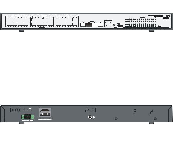
Figure 1-9 3Com Baseline Switch 2928-HPWR Plus front panel
|
|
|
|
|
|
|
|
|
|
|
|
|
|
|
|
|
|
|
|
|
|
|
|
|
|
|
|
|
|
|
|
|
|
|
|
|
|
|
|
|
|
|
|
|
|
|
|
|
|
|
|
|
|
|
|
|
|
|
|
|
|
|
|
|
|
|
|
|
|
|
|
|
|
|
|
|
|
|
|
|
|
|
|
|
|
|
|
|
|
|
|
|
|
|
|
|
|
|
|
|
|
|
|
|
|
|
|
|
|
|
|
|
|
|
|
|
|
|
|
|
|
|
|
|
|
|
|
|
|
|
|
|
|
|
|
|
|
|
|
|
|
|
|
|
|
|
|
|
|
|
|
|
|
|
|
|
|
|
|
|
|
|
|
|
|
|
|
|
|
|
|
|
|
|
|
|
|
|
|
|
|
|
|
|
|
|
|
|
|
|
|
|
|
|
|
|
|
|
|
|
|
|
|
|
|
|
|
|
|
|
|
|
|
|
|
|
|
|
|
|
|
|
|
|
|
|
|
|
|
|
|
|
|
|
|
|
|
|
|
|
|
|
|
|
|
|
|
|
|
|
|
|
|
|
|
|
|
|
|
|
|
|
|
|
|
|
|
|
|
|
|
|
|
|
|
|
|
|
|
|
|
|
|
|
|
|
|
|
|
|
|
|
|
|
|
|
|
|
|
|
|
|
|
|
|
|
|
|
|
|
|
|
|
|
|
|
|
|
|
|
|
|
|
|
|
|
|
|
|
|
|
|
|
|
|
|
|
|
|
|
|
|
|
|
|
|
|
|
|
|
|
|
|
|
|
|
|
|
|
|
|
|
|
|
|
|
|
|
|
|
|
|
|
|
|
|
|
|
|
|
|
|
|
|
|
|
|
|
|
|
|
|
|
|
|
|
|
|
|
|
|
|
|
|
|
|
|
(1) |
10/100/1000Base-T auto-sensing Ethernet port |
|
(2) |
Port status LED mode switching button |
||||||||||||||||||||||||||||||||||||||||||||||
(3) |
RPS status LED (RPS) |
|
(4) |
Port status LED |
||||||||||||||||||||||||||||||||||||||||||||||
(5) |
Power LED (Power) |
|
(6) |
Port mode LED |
||||||||||||||||||||||||||||||||||||||||||||||
(7) |
Console port |
|
|
(8) Port 1000Base-X SFP interface |
||||||||||||||||||||||||||||||||||||||||||||||
Rear Panel
Figure 1-10 3Com Baseline Switch 2928-HPWR Plus rear panel
|
|
|
|
|
|
|
|
|
|
|
|
|
|
|
|
|
|
|
|
|
|
|
|
|
|
|
|
|
|
|
|
|
|
|
|
|
|
|
|
|
|
|
|
|
|
|
|
|
|
|
|
|
|
|
|
|
|
|
|
|
|
|
|
|
|
|
|
|
|
|
|
|
|
|
|
|
|
|
|
|
|
|
|
|
|
|
|
|
|
|
|
|
|
|
|
|
|
|
|
|
|
|
|
|
|
|
|
|
|
|
|
|
|
|
|
|
|
|
|
|
|
|
|
|
|
|
|
|
|
|
|
|
|
|
|
|
|
|
|
|
|
|
|
|
|
|
|
|
|
|
|
|
|
|
|
|
|
|
|
|
|
|
|
|
|
|
|
|
|
|
|
|
|
|
|
|
|
|
|
|
|
|
|
|
|
|
|
|
|
|
|
|
|
|
|
|
|
|
|
|
|
|
|
|
|
|
|
|
|
|
|
|
|
|
|
|
|
|
|
|
|
|
|
|
|
|
|
|
|
|
|
|
|
|
|
|
|
|
|
|
|
|
|
|
|
|
|
|
|
|
|
|
|
|
|
|
|
|
|
|
|
|
|
|
|
|
|
|
|
|
|
|
|
|
|
|
|
|
|
|
|
|
|
|
|
|
|
|
|
|
|
|
|
|
|
|
|
|
|
|
|
|
|
|
|
|
|
|
|
|
(1) |
Screw hole of the plug |
(2) AC receptacle |
|
||||||||||||||||||||||||||
|
(3) |
Grounding screw |
(4) DC power receptacle |
|
||||||||||||||||||||||||||
Power Supply System
The 3Com Baseline Switch 2928-HPWR Plus can adopt AC power input, or DC power input, or both to provide backup
zAC power input:
Rated voltage range: 100 VAC to 240 VAC, 50 Hz or 60 Hz
Input voltage range: 90 VAC to 264 VAC, 47 Hz or 63 Hz
zDC power input
Rated voltage range: –52 VDC to –55 VDC
1-7

Only the RPS recommended by 3Com can be used for the 3Com Baseline Switch 2928-HPWR Plus. The –48 VDC power supply in the equipment room cannot be used directly. Otherwise, the device may be damaged.
Cooling System
The 3Com Baseline Switch 2928-HPWR Plus is equipped with six fans for heat dissipation.
Ports
Console Port
Each 3Com Baseline Switch 2900 Family provides one console port on the front panel. Table 1-2 describes the console port specifications.
Table 1-2 Console port specifications
|
Item |
|
Specification |
|
Connector type |
|
RJ-45 |
|
|
|
|
|
Compliant standard |
|
EIA/TIA-232 |
|
|
|
|
|
Transmission baud |
|
9600 bps to 115200 bps (defaulting to 38400 bps) |
|
rate |
|
|
|
|
|
|
|
|
|
|
|
Service |
|
z It can be connected to an ASCII terminal. |
|
|
z It can be connected to a serial port of a local or remote (through a pair of |
|
|
|
|
modems) PC running terminal emulation program. |
10/100/1000Base-T Ethernet Port
Each 3Com Baseline Switch 2900 Family provides 10/100/1000Base-T Ethernet ports on its front panel. Quantity of Ethernet ports varies with the device model, see Table 1-1 for details.
Table 1-3 describes the specifications of the 10/100/1000Base-T Ethernet ports.
Table 1-3 3Com Baseline Switch 2900 Family 10/100/1000Base-T Ethernet port specifications
|
Item |
|
Specification |
|
Connector type |
|
RJ-45 |
|
|
|
|
|
|
|
z 10 Mbps, full duplex |
|
Interface speed and operating mode |
|
z 100 Mbps, full duplex |
|
|
z 1000 Mbps, full duplex |
|
|
|
|
|
|
|
|
z MDI/MDI-X, auto-sensing |
|
Max transmission distance |
|
100 m (328.1 ft.) |
|
|
|
|
|
Transmission medium |
|
Category-5 unshielded twisted pair cable |
|
|
|
|
|
Standard |
|
IEEE 802.3i, IEEE 802.3u, IEEE 802.3ab |
|
|
|
|
|
|
1-8 |
|

1000Base-X SFP Interface
Each 3Com Baseline Switch 2900 Family provides four 1000Base-X SFP interfaces on its front panel. You can select the GE SFP transceivers described in Table 1-4.
Table 1-4 Transceivers supported by the 3Com Baseline Switch 2900 Family 1000Base-X SFP
interfaces
|
Transceiver |
|
Transceiver |
|
Central |
|
Connector |
|
|
type |
|
|
wavelength |
|
|
||
|
|
|
|
|
|
|
||
|
|
|
|
|
|
|
|
|
SFP-GE-SX-MM850-A 850 nm
SFP-GE-LX-SM1310-A
1310 nm |
LC |
SFP-GE-LH40-SM1310
GE SFP |
SFP-GE-LH40-SM1550 |
|
|
transceiver |
SFP-GE-LH70-SM1550 |
1550 nm |
|
|
|
||
|
|
|
|
|
|
|
|
|
SFP-GE-LX-SM1310-B |
TX: 1310 nm |
|
|
RX: 1490 |
|
|
|
IDI* |
|
|
|
nm |
|
|
|
|
LC |
|
|
|
|
|
|
SFP-GE-LX-SM1490-B |
TX: 1490 nm |
|
|
RX: 1310 |
||
|
IDI* |
||
|
|
nm |
|
|
|
|
|
|
SFP-GE-T |
— |
RJ-45 |
Fiber
50/125 µm multimode optical fiber
62.5/125 µm multimode optical fiber
9/125 µm single mode optical fiber
9/125 µm single mode optical fiber
Twisted pair cable
Max transmis sion distance
550 m
(0.34
miles)
275 m
(0.17
miles)
10 km
(6.21
miles)
40 km
(24.86
miles)
40 km
(24.86
miles)
70 km
(43.50
miles)
10 km
(6.21
miles)
100 m
(328.08
ft)
Note* that SFP-GE-LX-SM1310-BIDI and SFP-GE-LX-SM1490-BIDI must be used pairwise.
The types of SFP transceivers may update with time. For information about transceivers, contact 3Com technical support or marketing staff.
1-9
LEDs
Table 1-5 LEDs
|
LED |
|
Device support |
|
Description |
|
|
Power LED |
All series |
|
See “Power LED” on page 1-10. |
||
|
|
|
|
|
|
|
|
RPS status LED |
|
3Com Baseline Switch |
|
See “RPS Status LED” on page |
|
|
|
2928-HPWR Plus |
1-10. |
|
||
|
|
|
|
|||
|
|
|
|
|
|
|
|
|
|
3Com Baseline Switch |
|
|
|
|
Port mode LED |
|
2928-PWR Plus and 3Com |
|
See “Port Mode LED” on page 1-11. |
|
|
|
Baseline Switch 2928-HPWR |
|
|||
|
|
|
|
|
|
|
|
|
|
Plus |
|
|
|
|
|
|
|
|
|
|
|
10/100/1000Base-T |
|
|
|
See “10/100/1000Base-T |
|
|
auto-sensing Ethernet |
|
All series |
|
Auto-Sensing Ethernet Port Status |
|
|
port status LED |
|
|
LED” on page 1-11 |
||
|
|
|
|
|
|
|
|
1000Base-X SFP |
|
All series |
|
See “1000Base-X SFP Interface |
|
|
interface status LED |
|
Status LED” on page1-13. |
|||
|
|
|
||||
|
|
|
|
|
|
|
Power LED
The power LED indicates the operation status of the switch.
Table 1-6 Description of the power LED
|
LED |
Status |
Description |
|
|
|
Solid green |
The switch functions normally. |
|
|
|
|
|
|
|
|
Blinking green (1 Hz) |
The system is performing power-on self test (POST) or |
|
|
|
downloading software. |
||
|
Power |
|
||
|
|
|
||
Blinking green (3 Hz) |
The POST has failed or another fatal error has been |
|||
|
|
|||
|
|
detected. |
||
|
|
|
||
|
|
|
|
|
|
|
Off |
The switch has been powered off. |
|
|
|
|
|
RPS Status LED
The 3Com Baseline Switch 2928-HPWR Plus provides an RPS status LED on its front panel, indicating the working status of the RPS of the switch.
Table 1-7 Description of the RPS status LED
|
LED |
Status |
Description |
|
|
|
Solid green |
The RPS DC input is normal. |
|
|
RPS |
|
|
|
Off |
The RPS unit is not connected or the RPS DC input is |
|||
|
|
|||
|
|
abnormal. |
||
|
|
|
||
|
|
|
|
1-10

Port Mode LED
The port mode LED on the 3Com Baseline Switch 2928-PWR Plus/3Com Baseline Switch 2928-HPWR Plus can display the working status of a port for you to obtain more device information. You can use the port mode switching button to change the status of the port mode LED.
Table 1-8 3Com Baseline Switch 2928-PWR Plus/3Com Baseline Switch 2928-HPWR Plus port mode LED description
|
|
LED |
|
Status |
Description |
|
|
Mode |
|
Solid green |
Indicates port rate. |
|
|
|
|
|
|
|
|
|
Blinking green (1 Hz) |
Indicates port PoE power supply. |
|
|
|
|
|
||
|
|
|
|
|
|
10/100/1000Base-T Auto-Sensing Ethernet Port Status LED
zEach port of the 3Com Baseline Switch 2952-SFP Plus has a bi-color LED indicating its status; whereas each port of other models of the 3Com Baseline Switch 2900 Family has two LEDs, with only one in the ON state at a time.
zFor each port of the 3Com Baseline Switch 2928-PWR Plus and 3Com Baseline Switch 2928-HPWR Plus, the port mode LED and the status LED together indicate the port operation status.
Table 1-9 10/100/1000Base-T auto-sensing Ethernet port LEDs description
|
|
|
|
Port |
|
Ethernet port status |
|
|
|
|
||
|
|
Switch model |
|
mode |
|
|
|
Meaning |
|
|||
|
|
|
|
|
LED |
|
|
|
||||
|
|
|
|
LED |
|
|
|
|
|
|
||
|
|
|
|
|
|
|
|
|
|
|
|
|
|
|
|
|
|
|
|
|
|
|
|
|
|
|
|
|
|
|
|
|
|
On |
The port operates at a rate of 1000 |
|||
|
|
|
|
|
|
|
|
Mbps |
||||
|
|
|
|
|
|
|
|
|
|
|||
|
|
|
|
|
|
|
|
|
|
|
||
|
|
|
|
|
|
Green |
|
Fast blinking |
Data is being transmitted or received at |
|||
|
|
|
|
|
|
|
1000 Mbps |
|||||
|
|
|
|
|
|
|
|
|
|
|||
|
|
|
|
|
|
|
|
|
|
|
|
|
|
|
3Com Baseline |
|
|
|
|
Off |
|
The port is not up or does not operate at |
|||
|
|
|
|
|
|
|
1000 Mbps |
|||||
|
|
Switch |
|
|
|
|
|
|
|
|||
|
|
|
|
|
|
|
|
|
|
|
||
|
|
2920-SFP Plus |
— |
|
|
|
On |
The port operates at a rate of 10/100 |
||||
|
|
3Com Baseline |
|
|
|
Mbps |
||||||
|
|
|
|
|
|
|
|
|||||
|
|
Switch |
|
|
|
|
|
|
|
|
|
|
|
|
|
|
|
|
|
|
Data is being transmitted or received at |
||||
|
|
2928-SFP Plus |
|
|
|
|
Fast blinking |
|||||
|
|
|
|
|
|
10/100 Mbps |
||||||
|
|
|
|
|
|
Yellow |
|
|
|
|||
|
|
|
|
|
|
|
|
|
|
|
|
|
|
|
|
|
|
|
|
Blinking (3 |
The POST has failed |
||||
|
|
|
|
|
|
|
|
|||||
|
|
|
|
|
|
|
|
Hz) |
||||
|
|
|
|
|
|
|
|
|
|
|
||
|
|
|
|
|
|
|
|
|
|
|
||
|
|
|
|
|
|
|
|
Off |
The port is not up or does not operate at |
|||
|
|
|
|
|
|
|
|
10/100 Mbps |
||||
|
|
|
|
|
|
|
|
|
|
|||
|
|
|
|
|
|
|
|
|
|
|
|
|
1-11
|
|
|
|
|
Port |
|
|
Ethernet port status |
|
|
|
|
||
|
|
Switch model |
|
|
mode |
|
|
|
|
Meaning |
|
|||
|
|
|
|
|
|
LED |
|
|
|
|||||
|
|
|
|
|
LED |
|
|
|
|
|
|
|||
|
|
|
|
|
|
|
|
|
|
|
|
|
|
|
|
|
|
|
|
|
|
|
|
|
|
|
|
|
|
|
|
|
|
|
|
|
|
Solid green |
|
|
|
The port operates at a rate of 1000 |
||
|
|
|
|
|
|
|
|
|
|
|
Mbps |
|||
|
|
|
|
|
|
|
|
|
|
|
|
|
||
|
|
|
|
|
|
|
|
|
|
|
|
|
|
|
|
|
|
|
|
|
|
|
Fast blinking green |
|
Data is transmitted or received at a rate |
||||
|
|
|
|
|
|
|
|
|
of 1000 Mbps |
|||||
|
|
|
|
|
|
|
|
|
|
|
|
|
||
|
|
3Com Baseline |
|
|
|
|
|
|
|
|
|
|
|
|
|
|
|
|
|
|
|
|
|
|
|
The port operates at a rate of 10/100 |
|||
|
|
Switch |
— |
|
Solid yellow |
|
|
|
||||||
|
|
|
|
|
|
Mbps |
||||||||
|
|
2952-SFP Plus |
|
|
|
|
|
|
|
|
|
|||
|
|
|
|
|
|
|
|
|
|
|
|
|
||
|
|
|
|
|
|
|
|
Fast blinking yellow |
|
Data is transmitted or received at a rate |
||||
|
|
|
|
|
|
|
|
|
of 10/100 Mbps |
|||||
|
|
|
|
|
|
|
|
|
|
|
|
|
||
|
|
|
|
|
|
|
|
|
|
|
|
|
|
|
|
|
|
|
|
|
|
|
Off |
|
|
|
The port is not up or the POST has |
||
|
|
|
|
|
|
|
|
|
|
|
failed |
|||
|
|
|
|
|
|
|
|
|
|
|
|
|
||
|
|
|
|
|
|
|
|
|
|
|
|
|
||
|
|
|
|
|
|
|
|
|
|
On |
The port operates at a rate of 1000 |
|||
|
|
|
|
|
|
|
|
|
|
Mbps |
||||
|
|
|
|
|
|
|
|
|
|
|
|
|||
|
|
|
|
|
|
|
|
|
|
|
|
|
||
|
|
|
|
|
|
|
|
Green |
|
Fast blinking |
Data is transmitted or received at a rate |
|||
|
|
|
|
|
|
|
|
|
of 1000 Mbps |
|||||
|
|
|
|
|
|
|
|
|
|
|
|
|||
|
|
|
|
|
|
|
|
|
|
|
|
|
|
|
|
|
|
|
|
|
|
|
|
|
Off |
|
The port is not up or does not operate at |
||
|
|
|
|
|
|
|
|
|
|
|
1000 Mbps |
|||
|
|
|
|
|
Solid |
|
|
|
|
|
|
|||
|
|
|
|
|
|
|
|
|
|
|
|
|
||
|
|
|
|
|
|
|
|
|
|
|
|
|
||
|
|
|
|
|
green |
|
|
|
On |
The port operates at a rate of 10/100 |
||||
|
|
|
|
|
(rate |
|
|
|
Mbps |
|||||
|
|
|
|
|
|
|
|
|
|
|||||
|
|
|
|
|
mode) |
|
|
|
|
|
|
|
|
|
|
|
|
|
|
|
|
|
Fast blinking |
Data is transmitted or received at a rate |
|||||
|
|
|
|
|
|
|
|
|
|
|||||
|
|
|
|
|
|
|
|
|
|
of 10/100 Mbps |
||||
|
|
|
|
|
|
|
|
Yellow |
|
|
|
|||
|
|
|
|
|
|
|
|
|
|
|
|
|
|
|
|
|
|
|
|
|
|
|
|
Blinking (3 |
The POST has failed |
||||
|
|
|
|
|
|
|
|
|
|
|||||
|
|
3Com Baseline |
|
|
|
|
|
|
Hz) |
|||||
|
|
|
|
|
|
|
|
|
|
|
||||
|
|
|
|
|
|
|
|
|
|
|
|
|
||
|
|
Switch |
|
|
|
|
|
|
Off |
|
The port is not up or does not operate at |
|||
|
|
2928-PWR Plus |
|
|
|
|
|
|
|
10/100 Mbps. |
||||
|
|
|
|
|
|
|
|
|
|
|
||||
|
|
3Com Baseline |
|
|
|
|
|
|
|
|
|
|
|
|
|
|
|
|
|
|
|
|
On |
PoE power supply is normal. |
|||||
|
|
Switch |
|
|
|
|
|
|
||||||
|
|
|
|
|
|
|
|
|
|
|
|
|
||
|
|
2928-HPWR |
|
|
|
|
|
|
|
|
Power consumption of the device |
|||
|
|
Plus |
|
|
|
|
|
|
|
|
||||
|
|
|
|
|
|
|
|
Blinking at 3 |
attached to the port exceeds the upper |
|||||
|
|
|
|
|
|
|
|
Green |
|
limit of the power supply consumption of |
||||
|
|
|
|
|
|
|
|
|
Hz |
the port, or the available power of the |
||||
|
|
|
|
|
|
|
|
|
|
|
|
switch is not enough for power supply of |
||
|
|
|
|
Blinking |
|
|
|
|
|
the port. |
||||
|
|
|
|
|
|
|
|
|
|
|
|
|||
|
|
|
|
green |
|
|
|
Off |
|
No PoE power supply is provided on the |
||||
|
|
|
|
(PoE |
|
|
|
|
port. |
|||||
|
|
|
|
|
|
|
|
|
|
|||||
|
|
|
|
mode) |
|
|
|
|
|
|
|
|
||
|
|
|
|
|
|
|
On |
The device connected to the interface is |
||||||
|
|
|
|
|
|
|
|
|
|
|||||
|
|
|
|
|
|
|
|
|
|
not a PD device or a PoE failure occurs |
||||
|
|
|
|
|
|
|
|
|
|
|
|
|||
|
|
|
|
|
|
|
|
|
|
|
|
|
|
|
|
|
|
|
|
|
|
|
Yellow |
|
Blinking (3 |
The POST has failed |
|||
|
|
|
|
|
|
|
|
|
Hz) |
|||||
|
|
|
|
|
|
|
|
|
|
|
|
|
||
|
|
|
|
|
|
|
|
|
|
|
|
|
||
|
|
|
|
|
|
|
|
|
|
Off |
No PoE power supply is provided on the |
|||
|
|
|
|
|
|
|
|
|
|
port or PoE power supply is normal. |
||||
|
|
|
|
|
|
|
|
|
|
|
|
|||
|
|
|
|
|
|
|
|
|
|
|
|
|
|
|
1-12

1000Base-X SFP Interface Status LED
For 3Com Baseline Switch 2928-PWR Plus and 3Com Baseline Switch 2928-HPWR Plus, the port mode switching button does not take effect for the 1000Base-X SFP interface LEDs.
Table 1-10 1000Base-X SFP interface status LEDs description
LED |
Meaning |
|
Solid green |
The port operates at a rate of 1000 Mbps |
|
The port is transmitting data at 1000 Mbps |
||
|
||
|
|
|
Blinking green |
The LED is fast blinking when data is being received on the port. |
|
|
|
|
Off |
No link is present on the port |
|
|
|
1-13
Loading...