


 Loading...
3Com® Baseline Switch 2816-SFP Plus (3C16485)
User Guide
DUA1648-5AAA02
|
1 |
|
|
4 |
|
9 |
|
5 |
|
|
8 |
|
12 |
13 |
|
|
|
|
|
16 |
M |
|
odule |
Present |
Link/A |
ctivity : |
Green = |
|
|
|
|
|
|
||
Flash = A |
|
1000M, |
|
|
|
|
||||
|
|
ctivity, D |
|
Y |
|
|
|
|||
|
|
|
|
uplex : |
On |
|
|
|
||
|
|
|
|
|
|
=ellow = 1 |
0/100 |
|
||
|
|
|
|
|
|
|
Full, |
|
M, |
|
|
|
|
|
|
|
|
|
Off = |
|
|
|
|
|
|
|
|
|
|
|
Half |
|
Baseline |
|
Swi |
|
tch 2 |
816-SFP |
|
3C16485
Copyright © 3Com Technologies, 2004. All rights reserved. No part of this documentation may be reproduced in any form or by any means or used to make any derivative work (such as translation, transformation, or adaptation) without written permission from 3Com Technologies.
3Com Technologies reserves the right to revise this documentation and to make changes in content from time to time without obligation on the part of 3Com Technologies to provide notification of such revision or change.
3Com Technologies provides this documentation without warranty of any kind, either implied or expressed, including, but not limited to, the implied warranties of merchantability and fitness for a particular purpose. 3Com may make improvements or changes in the product(s) and/or the program(s) described in this documentation at any time.
UNITED STATES GOVERNMENT LEGENDS:
If you are a United States government agency, then this documentation and the software described herein are provided to you subject to the following restricted rights:
For units of the Department of Defense:
Restricted Rights Legend: Use, duplication or disclosure by the Government is subject to restrictions as set forth in subparagraph (c) (1) (ii) for restricted Rights in Technical Data and Computer Software clause at 48 C.F.R. 52.227-7013. 3Com Centre, Boundary Way, Maylands Park South, Hemel Hempstead, Herts, HP2 7YU, U.K.
For civilian agencies:
Restricted Rights Legend: Use, reproduction or disclosure is subject to restrictions set forth in subparagraph (a) through (d) of the Commercial Computer Software - Restricted Rights Clause at 48 C.F.R. 52.227-19 and the limitations set forth in 3Com Corporation’s standard commercial agreement for the software. Unpublished rights reserved under the copyright laws of the United States.
If there is any software on removable media described in this documentation, it is furnished under a license agreement included with the product as a separate document, in the hard copy documentation, or on the removable media in a directory file named LICENSE.TXT. If you are unable to locate a copy, please contact 3Com and a copy will be provided to you.
Unless otherwise indicated, 3Com registered trademarks are registered in the United States and may or may not be registered in other countries.
3Com, the 3Com logo and SuperStack are registered trademarks of 3Com Corporation. Other brand and product names may be registered trademarks or trademarks of their respective holders.
Environmental Statement
It is the policy of 3Com Corporation to be environmentally-friendly in all operations.
To uphold our policy, we are committed to:
■Establishing environmental performance standards that comply with national legislation and regulations.
■Conserving energy, materials and natural resources in all operations.
■Reducing the waste generated by all operations.
■Ensuring that all waste conforms to recognised environmental standards.
■Maximising the recyclable and reusable content of all products.
■Ensuring that all products can be recycled, reused and disposed of safely.
■Ensuring that all products are labelled according to recognised environmental standards.
■Improving our environmental record on a continual basis.
Contents
About this Guide |
|
|
Naming Convention |
5 |
|
Conventions 5 |
|
|
Feedback about this User Guide |
6 |
|
Product Registration |
6 |
|
Introduction |
|
|
Baseline Switch 2816-SFP Plus |
7 |
|
Package Contents |
8 |
|
How to Use the Baseline Switch 2816-SFP Plus
Front and Rear Panels |
9 |
|
|
Front Panel Features |
9 |
|
|
Rear Panel Features |
11 |
|
|
Installation Recommendations |
|
||
Positioning the Switch |
13 |
|
|
Rack Mounting or Free Standing |
13 |
||
Power Supply |
13 |
|
|
Power Up 13 |
|
|
|
Spot Checks |
14 |
|
|
Connecting to a Network Device |
14 |
||
SFP Operation |
14 |
|
|
|
Approved SFP Transceivers |
14 |
|
||
Inserting an SFP Transceiver |
14 |
|
||
Removing an SFP Transceiver |
15 |
|
||
Mounting Kit Instructions |
|
|
|
|
Introduction |
17 |
|
|
|
Rack Mounting the Units |
17 |
|
|
|
Automatic IP Configuration |
|
|
||
How Your Switch Obtains IP Information |
19 |
|||
How Automatic IP Configuration Works |
19 |
|||
Automatic Process |
19 |
|
|
|
Switch Configuration
Navigating Through the Switch Configuration Pages 21
Main Menu |
21 |
||
Option Tabs |
|
21 |
|
Fan Status |
22 |
||
Summary Screen |
|
22 |
|
Password |
23 |
|
|
IP Settings |
23 |
|
|
Port Configuration |
24 |
||
VLANs 25 |
|
|
|
VLAN Configuration Examples 26 |
|||
Create VLANs |
28 |
||
Delete VLANs |
|
28 |
|
Modify VLANs |
29 |
||
3
Membership VLANs |
29 |
|||
Trunking |
30 |
|
|
|
Traffic Monitoring |
32 |
|
||
System Tools |
32 |
|
|
|
Restart |
|
32 |
|
|
Configuration |
33 |
|
||
Upgrade |
33 |
|
|
|
Spanning Tree |
35 |
|
||
802.1p Prioritization |
36 |
|||
Support |
37 |
|
|
|
Using Discovery
Running the Discovery Application 39
Windows Installation (95/98/XP/2000/2003 Server/NT) 39
Problem Solving
Safety Information
L'INFORMATION DE SÉCURITÉ IMPORTANTE
WICHTIGE SICHERHEITSINFORMATIONEN
Technical Information
Related Standards 49
Environmental 49
Physical 49
Electrical 49
Technical Support |
|
|
Where To Go For Help |
51 |
|
Register Your Product to Gain Service Benefits 51 |
||
Purchase Value-Added Services |
51 |
|
Troubleshoot Online |
51 |
|
Purchase Value-Added Services |
51 |
|
Contact Us 51
Telephone Technical Support and Repair 52
Glossary
Index
Regulatory Notices
4

ABOUT THIS GUIDE
This guide is intended for use by those responsible for installing and setting up network equipment; consequently, it assumes a basic working knowledge of LANs (Local Area Networks).
If a release note is shipped with this 3Com Baseline Switch 2816-SFP Plus and contains information that differs from the information in this guide, follow the information in the release note.
Most user guides and release notes are available in Adobe Acrobat Reader Portable Document Format (PDF) on the 3Com World Wide Web site:
http://www.3com.com
Naming Convention
Throughout this guide, the 3Com Baseline Switch 2816-SFP Plus is referred to as the Switch.
Category 3 and Category 5 Twisted Pair Cables are referred to as Twisted Pair Cables throughout this guide.
Conventions
Table 1 and Table 2 list conventions that are used throughout this guide.
|
Table 1 |
Notice Icons |
|
|
|
|
|
||
Icon |
Notice Type |
Description |
||
|
|
|
||
|
Information note |
Information that describes important |
||
|
|
|
|
features or instructions |
|
|
|
|
|
|
Caution |
|
Information that alerts you to potential |
|
|
|
|
|
loss of data or potential damage to an |
|
|
|
|
application, system, or device |
|
|
|
|
|
|
Warning |
|
Information that alerts you to potential |
|
|
|
|
|
personal injury |
|
|
|
|
|
|
Table 2 |
Text Conventions |
|
|
|
|
|
|
|
Convention |
|
Description |
|
|
|
|
|||
The words “enter” |
When you see the word “enter” in this guide, you |
|||
and “type” |
|
must type something, and then press Return or Enter. |
||
|
|
|
Do not press Return or Enter when an instruction |
|
|
|
|
simply says “type.” |
|
|
|
|
||
Keyboard key |
|
If you must press two or more keys simultaneously, |
||
names |
|
|
the key names are linked with a plus sign (+). |
|
|
|
|
Example: |
|
Press Ctrl+Alt+Del
5

Table 2 Text Conventions (continued)
Convention |
Description |
|
|
|
|
Words in italics |
Italics are used to: |
|
|
■ |
Emphasize a point. |
|
■ |
Denote a new term at the place where it is defined |
|
|
in the text. |
|
■ |
Identify menu names, menu commands, and soft- |
ware button names. Examples:
From the Help menu, select Contents. Click OK.
Feedback about this User Guide
Your suggestions are very important to us. They will help make our documentation more useful to you. Please e-mail comments about this document to 3Com at:
pddtechpubs_comments@3com.com
Please include the following information when commenting:
■Document title
■Document part number (on the title page)
■Page number (if appropriate)
Example:
■3Com Baseline Switch 2816-SFP Plus User Guide
■Part Number DUA1648-5AAA0x
■Page 24
Do not use this e-mail address for technical support questions. For information about contacting Technical Support, please refer to “Support” on page 37.
The Switch is part of the extensive Baseline range of 3Com products. This range includes hubs, switches, power systems and other networking equipment, and is continually being developed. Contact your supplier for the latest product information and to order these products.
Product Registration
You can now register your Baseline Switch on the 3Com web site to receive up-to-date information on your product:
http://esupport.3com.com
6
INTRODUCTION
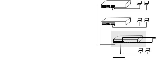
The 3Com® Baseline Switch 2816-SFP Plus is a versatile, |
|
|
|
Figure 1 Network Plan |
|
|||||||
easy-to-use configurable Switch. It is ideal for users who want |
|
|
|
|
|
|
|
|
|
|
|
Endstations on switched |
the high-speed performance of 10/100/1000 switching with the |
|
|
|
|
|
|
Baseline 10/100 Switch |
|||||
|
|
|
|
|
|
100 Mbps connections |
||||||
added functionality of Gigabit links, but do not need |
|
|
|
|
|
|
|
|
|
|
|
|
sophisticated management capabilities. The Switch is shipped |
|
|
|
|
|
|
|
|
|
|
|
|
ready for use. No configuration is necessary. |
|
|
|
|
|
|
|
|
|
|
|
|
|
|
|
|
|
|
|
Baseline 10/100 Switch |
Endstations on switched |
||||
Baseline Switch 2816-SFP Plus |
|
|
|
|
|
|
100 Mbps connections |
|||||
|
|
|
|
|
|
|
|
|
|
|
|
|
The Switch has 16 shielded RJ-45, 10/100/1000 Mbps |
|
|
|
auto-negotiating ports and four Small Form Factor Pluggable |
|
|
|
(SFP) transceiver slots on the front panel for easy, flexible |
BaselinelineSwitchSwitch28162250-SFP Plus |
|
|
connection to fiber-based Gigabit media. Each 10/100/1000 |
1000 Mbps copper or Fiber |
||
|
|||
Mbps port automatically determines the speed and duplex mode |
|
connection to backbone |
|
|
or server/worksation |
||
of the connected equipment and provides a suitable switched |
|
|
|
connection. The four SFP ports support fiber Gigabit Ethernet |
|
|
|
short-wave (SX) and long-wave (LX) SFP transceivers in any |
|
Endstations on |
|
|
switched 100 Mbps or 1000 Mbps |
||
combination. This offers you the flexibility of using SFP |
|
||
|
connections |
||
transceivers to provide connectivity between the Switch and a |
1000 Mbps link |
|
|
1000 Mbps core network. |
|
||
10 Mbps or 100 Mbps link |
|
The Switch is suitable for office use where it can be free-standing, or rack mounted (in a wiring closet or equipment room).
7

Package Contents
The Switch comes with:
■One power cord
■Four standard height, self-adhesive rubber pads
■One mounting kit
■Installation CD
■This User Guide
■Warranty flyer
The Switch is powered from the AC supply.
8
HOW TO USE THE BASELINE SWITCH 2816-SFP PLUS
Front and Rear Panels
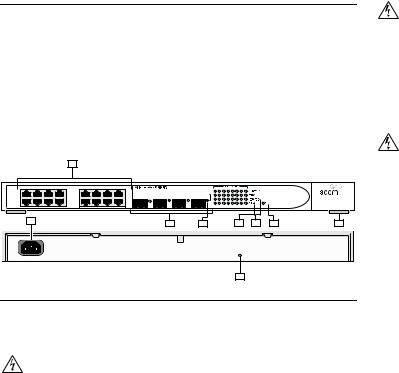
The front panel of the Switch contains a series of indicator lights (LEDs) that help describe the state of various networking and connection operations.
The numbers in this diagram refer to numbered sections in “Front Panel Features” on page 9, and “Rear Panel Features” on page 11.
AVERTISSEMENT: Points d’accès RJ-45. Ceux-ci sont protégés par des prises de données. Ils ne peuvent pas être utilisés comme prises de téléphone conventionnelles standard, ni pour la connection de l’unité à un réseau téléphonique central privé ou public. Raccorder seulement connecteurs de données RJ-45, systèmes de réseaux de téléphonie ou téléphones de réseaux à ces prises.
Il est possible de raccorder des câbles protégés ou non protégés avec des jacks protégés ou non protégés à ces prises de données.
|
Figure 2 |
Front and Rear Panels |
|
||
|
|
1 |
|
|
|
|
|
|
|
|
Baseline Switch 2816-SFP Plus |
1 |
4 |
|
5 |
8 |
|
|
|
|
|
|
Module Present |
|
|
|
|
|
3C16485 |
9 |
12 |
|
13 |
16 |
Link/Activity : Green = 1000M, Yellow = 10/1000M, |
|
|
|
|
|
Flash = Activity, Duplex : On = Full, Off = Half |
8 |
2 |
4 |
5 |
3 |
6 |
7 |
|
|
|
9 |
|
|
|
Front Panel Features
1 RJ-45 10/100/1000 Ports
WARNING: RJ-45 Ports. These are shielded RJ-45 data sockets. They cannot be used as standard traditional telephone sockets, or to connect the unit to a traditional PBX or public telephone network. Only connect RJ-45 data connectors, network telephony systems, or network telephones to these sockets.
Either shielded or unshielded data cables with shielded or unshielded jacks can be connected to these data sockets.
WARNHINWEIS: RJ-45-Porte. Diese Porte sind geschützte Datensteckdosen. Sie dürfen weder wie normale traditionelle Telefonsteckdosen noch für die Verbindung der Einheit mit einem traditionellem privatem oder öffentlichem Telefonnetzwerk gebraucht werden. Nur RJ-45-Datenanscluße, Telefonnetzsysteme or Netztelefone an diese Steckdosen anschließen.
Entweder geschützte oder ungeschützte Buchsen dürfen an diese Datensteckdosen angeschlossen werden.
The Switch has 16 10/100/1000 Mbps auto-negotiating ports. Each port supports automatic MDI/MDI-X detection and can be connected to either a 10BASE-T, 100BASE-TX, or a 1000BASE-T device.
Ports 1 to 16 are auto-negotiating: their speed and duplex mode (half duplex or full duplex for 10BASE-T and 100BASE-TX, full duplex only for 1000BASE-T) are automatically determined by the capabilities of the connected device.
9

CAUTION: The Switch supports full duplex auto-negotiation. If auto-negotiation is disabled for 1000BASE-T, then the Switch uses the forced-mode default of 100 full duplex mode. If the connected device does not support auto-negotiation, the Switch will operate in half duplex mode (even if the attached device is operating in full duplex mode). In such a configuration, you may notice some degradation of network performance. 3Com recommends that you use devices that are capable of auto-negotiation (and that you ensure that auto-negotiation is enabled, if it is a configurable option).
2 SFP Ports
The Small Form Factor Pluggable (SFP) ports are numbered 13 to 16. If an SFP transceiver (purchased separately) is installed in a slot and is active, the associated RJ-45 port of the same number is disabled.
The four SFP ports support fiber Gigabit Ethernet short-wave (SX) and long-wave (LX) SFP transceivers in any combination. This offers you the flexibility of using SFP transceivers to provide connectivity between the Switch and remote 1000 Mbps workgroups or to create a high-capacity aggregated link backbone connection.
SFP ports are numbered 13-16 on the Switch. When an SFP port is active it has priority over the 10/100/1000 port of the same number. The corresponding 10/100/1000 port is disabled when an SFP transceiver is plugged in.
3 Link/Activity Status LEDs
The following table lists LEDs visible on the front of the Switch, and how to read their status according to color.
Status |
Meaning |
|
|
Green |
The link is operating at 1000 Mbps. |
Yellow |
The link is operating at 10 or 100 Mbps. |
Flashing |
Packets are being received or transmitted on the port at 1000 |
Green |
Mbps. |
Flashing |
Packets are being received or transmitted on the port at 10 or |
Yellow |
100 Mbps. |
Flashing |
Port disabled or link loopback error. |
Yellow to |
|
Green |
|
Off |
The link has not been established, either nothing is connected |
|
to the port, or there is a problem: |
■Check that the attached device is powered on.
■Check that the cable or fiber is the correct type and is not faulty.
■For fiber connections, ensure that the receive (RX) and transmit (TX) cable connectors are not swapped.
If these checks do not identify the cause of the problem, it may be that the unit or the device connected to the port is faulty. Contact your supplier for further advice.
10
4 Module Active LEDs
The Module Active LEDs shows the status of any SFP modules that are installed.
Status |
Meaning |
|
|
Green |
Fiber SFP is inserted in the slot. |
Off |
No fiber SFP is inserted in the slot. |
|
|
5 Port Duplex LEDs
The second and fourth (bottom) row of Status LEDs, which are colored yellow, show the duplex status of the related ports.
Status |
Meaning |
|
|
Off |
No link, not yet negotiated or the port is operating in |
|
half-duplex mode. |
Yellow |
The port is operating in full-duplex mode. |
|
|
6 Power LED
The Power LED shows the power status of the Switch:
Status |
Meaning |
|
|
|
|
Green |
The unit is powered on and ready for use. |
|
Off |
■ |
The unit is not receiving power: |
|
■ |
Check that the power cord is connected correctly. |
|
■ |
If the unit still does not operate, contact your supplier. |
Status Meaning
Flashing ■ Power-on self test is in progress.
Green
Yellow ■ Power-on self test or loopback test failed. Switch is in failsafe mode.
7 Self-adhesive Pads
The unit is supplied with four self-adhesive rubber pads.
Do not apply the pads if you intend to rack mount the unit.
If the unit is to be part of a free-standing stack, apply the pads to each marked corner area on the underside of the unit. Place the unit on top of the lower unit, ensuring that the pads locate with the recesses of the lower unit.
Rear Panel Features
8 Power Supply
The Switch automatically adjusts to the supply voltage. Only use the power cord that is supplied with the unit.
9 Recovery button
The recovery button reinitializes the Switch. This returns the Switch to the factory default settings if, for example, you have forgotten the default IP address, or forgotten your user name or password.
11

CAUTION: 3Com recommends that you back up your configuration settings before you recover the Switch, otherwise your configuration will be lost. Refer to “Configuration” on page 33 for details.
12

INSTALLATION RECOMMENDATIONS
Positioning the Switch
When deciding where to position the Switch ensure that:
■It is accessible and cables can be connected easily.
■Cabling is away from sources of electrical noise. These include lift shafts, microwave ovens, and air conditioning units. Electromagnetic fields can interfere with the signals on copper cabling and introduce errors, therefore slowing down your network.
■Water or moisture cannot enter the case of the unit.
■Air flow around the unit and through the vents in the side of the case is not restricted (3Com recommends that you provide a minimum of 25 mm (1 in.) clearance).
■The air is as free from dust as possible.
■Temperature operating limits are not likely to be exceeded. It is recommended that the unit is installed in a clean, air conditioned environment.
It is always good practice to wear an anti-static wrist strap when installing network equipment, connected to a ground point. If one is not available, try to keep in contact with a grounded rack and avoid touching the unit's ports and connectors, if possible. Static discharge can cause reliability problems in your equipment.
Rack Mounting or Free Standing
The unit can be mounted in a 19-inch equipment rack using the Mounting Kit, (refer to “Mounting Kit Instructions” on page 17), or it can be free standing. Do not place objects on top of the unit or stack.
CAUTION: If installing the Switch in a free-standing stack of different size Baseline or Superstack 3 units, the smaller units must be installed above the larger ones. Do not have a free-standing stack of more than six units.
Power Supply
Power problems can be the cause of serious failures and downtime in your network. Ensure that the power input to your system is clean and free from sags and surges to avoid unforeseen network outages. We recommend that you install power conditioning, especially in areas prone to black outs, power dips and electrical storms.
The unit is intended to be grounded. Ensure it is connected to earth ground during normal use. Installing proper grounding helps to avoid damage from lightning and power surges.
Power Up
Use the following sequence to power up the Switch:
1Check the network connections and cables.
2Connect the power supply cable to the appropriate power socket on the rear panel of the unit; refer to “Power Supply” on
page 11.
3Connect the plug to the power supply outlet socket and switch on the power supply at the socket.
When the Switch is powered on, the Power LED should light up. If it is not, refer to “Power LED” on page 11.
13

Spot Checks
At frequent intervals you should visually check the Switch. Regular checks can give you an early warning of a possible failure; any problems can then be attended to when there will be least effect on users. Check the following:
Cabling |
Check that all external cabling connections are secure |
|
and that no cables are pulled taut. |
Cooling fan |
Where possible, check that the cooling fan is operating |
|
by listening to the unit. The fan is fitted near to the |
|
front right hand side of the unit (when viewed from the |
|
front). |
|
|
If you experience any problems operating the Switch, refer to “Problem Solving” on page 41.
Connecting to a Network Device
To connect a device to the Switch use Category 5 unshielded or shielded (screened) 100 Ohm TP cable (or Category 3 cable for a 10 Mbps connection). The maximum length of cable for each connection is 100 m (328 ft). Connect one end of the cable to an RJ-45 port on the Switch and the other end to the appropriate RJ-45 port on the connecting device.
3Com recommends the use of Category 5e or 6 cables for 1000BASE-T operation.
SFP Operation
The following sections describe how to insert an SFP transceiver into an SFP slot.
SFP transceivers are hot-insertable and hot-swappable. You can remove them from and insert them into any SFP port without having to power down the Switch.
Approved SFP Transceivers
The following list of approved SFP transceivers is correct at the time of publication:
■3CSFP91 SFP (SX)
■3CSFP92 SFP (LX)
To access the latest list of approved SFP transceivers for the Switch on the 3Com Corporation World Wide Web site, enter this URL into your internet browser:
http://www.3com.com
Inserting an SFP Transceiver
To be recognised as valid, the SFP transceiver must have the following characteristics:
■1000BASE-SX or 1000BASE-LX media type:
■1000BASE-SX SFP transceiver
Use this transceiver to connect the Switch directly to a multimode fiber-optic cable.
■1000BASE-LX SFP transceiver
Use this transceiver to connect the Switch directly to a single-mode fiber-optic cable or to multimode fiber using a conditioned launch cable.
If the SFP transceiver is faulty, it will not operate within the Switch. See “Problem Solving” on page 41.
14
Use of non-3Com SFPs is not recommended. If the SFP transceiver is invalid it will not be recognised by the Switch.
Use the following sequence of steps to activate the SFP ports:
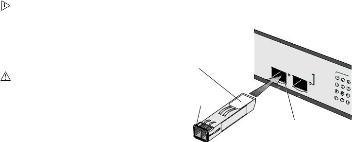
1Hold the transceiver so that the fiber connector is toward you and the product label is visible, as shown in Figure 3. Ensure the wire release lever is closed (in the upright position).
2Gently slide the transceiver into the SFP slot until it clicks into place.
CAUTION: SFP transceivers are keyed and can be properly inserted only one way. If the transceiver does not click when you insert it, remove it, turn it over, and reinsert it.
3Remove the plastic protective cover, if fitted.
4Connect the fiber cable.
5The transceiver connects to the network using a duplex LC connector. Attach a male duplex LC connector on the network cable into the duplex LC connector on the transceiver.
6Connect the other end of the cable to a device fitted with an appropriate Gigabit Ethernet connection.
7Check the Module Active LEDs on the front of the Switch to ensure that it is operating correctly.
Figure 3 Inserting an SFP Transceiver
Product label
Wire release lever
Module |
Present |
|
Link/Activity |
: |
Flash |
|
= |
|
Act |
|
Suitable slot on host Switch
Removing an SFP Transceiver
If you wish to remove the transceiver (it is not necessary to power-down your Switch):
1Disconnect the cable from the transceiver.
2Move the wire release lever downwards until it is pointing toward you.
3Pull the wire release lever toward you to release the catch mechanism; the transceiver will then easily slide out.
15
16
MOUNTING KIT INSTRUCTIONS |
|
|
|
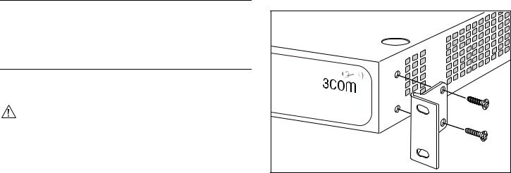
Figure 4 Back Mounting the Units |
|
Introduction |
|
|
|
The Switch is supplied with two mounting brackets and four |
|
|
screws. These are used for rack mounting the unit. When |
|
|
mounting the unit, you should take note of the guidelines given |
|
|
in “Positioning the Switch” on page 13. |
|
|
Baseline |
|
|
Switch 2816- |
|
|
SFP |
|
|
|
Plus |
Rack Mounting the Units |
|
|
|
The Switch is 1U high and will fit in a standard 19-inch rack. |
|
|
CAUTION: Disconnect all cables from the unit before continuing. |
|
|
Remove the self-adhesive pads from the underside of unit, if |
|
|
already fitted. |
|
1 |
Place the unit the right way up on a hard, flat surface with the |
|
|
front facing towards you. |
|
2 |
Locate a mounting bracket over the mounting holes on one side |
|
|
of the unit. |
|
3 |
Insert the two screws supplied in the mounting kit and fully |
|
|
tighten with a suitable screwdriver. |
|
4 |
Repeat the two previous steps for the other side of the unit. |
|
5 |
Insert the unit into the 19-inch rack and secure with suitable |
|
|
screws (not provided). |
|
6 |
Reconnect the cables. |
|
17
18

AUTOMATIC IP CONFIGURATION
This chapter explains more about IP addresses and how automatic IP configuration works on the Switch.
For details on how to view and amend your Switch’s IP settings, refer to “IP Settings” on page 23.
Switch’s MAC address in the DHCP server’s lease list. Refer to “IP Settings” on page 23.
3Com recommends that you do not use DHCP Addressing, unless you have experience of configuring and managing a DHCP server.
How Your Switch Obtains IP Information
Your Switch can obtain IP information using one of the following methods:
■Automatic IP Configuration (default) — the Switch will configure itself with its default IP address 169.254.x.y,where x and y are the last two bytes of the Switch’s MAC address.
Refer to “Automatic Process” on page 19 for details on how the Switch automatically obtains IP address information.
■Static IP Configuration — you can manually input the IP information (IP address, subnet mask, and default gateway). Refer to “IP Settings” on page 23. If your computers are configured with static addresses and you do not wish to change this, then you should use the Discovery program on the Switch CD-ROM to detect and configure your Switch.
For details on how to use Discovery to detect the Switch on the network, refer to “Using Discovery” on page 39.
■DHCP Addressing — DHCP addressing is a dynamic mechanism which the Switch uses to obtain an IP address lease from the DHCP server which is located on your network. If you select DHCP addressing, you will only be able to find out the IP address of the Switch by cross referencing the
How Automatic IP Configuration Works
When your Switch is powered up for the first time the IP configuration setting is set to automatic — this is the default setting.
If your Switch has been powered up before, whichever of the three options for IP configuration (automatic, static or DHCP) was last configured is activated when the Switch powers up again.
Automatic Process
To detect its IP information using the automatic configuration process, the Switch goes through the following sequence of steps:
1The Switch tries to configure itself with the default IP address 169.254.x.y,where x and y are converted from the last two bytes of the Switch’s MAC address.
For example, if the MAC address is 08004E000102, the IP address would be 169.254.1.2. This address is used if the Switch is operating in a standalone mode, or no other Switches on the network have this IP address.
2If this default IP address is already in use on the network then the Switch detects this, and increments the last byte of the MAC address by one to generate its IP address. The IP address would therefore become 169.254.1.3.
19
3 The Switch repeats step 2 until an unused IP address is found.
20
Loading...